Atkinson Differential Engine

Home Model Engine Machinist Forum

Help Support Home Model Engine Machinist Forum:

This site may earn a commission from merchant affiliate links, including eBay, Amazon, and others.

jasonh

Dogged Duffer
Joined
Sep 6, 2012
Messages
95
Reaction score
72
Not being content with already having an engine project going, I decided to have a go at the Vince Gingery Atkinson differential design. This is another engine designed by Mr Atkinson in the late 19th century, but it is quite unlike the Atkinson cycle engine that is more familiar to people.

This is a 4 stroke IC engine, but it it has 2 pistons working in a single cylinder. The two pistons work in opposition with each other for compression, power, exhaust and intake cycles. It's a bit reminiscent of the Comer "knocker" engines- although I think they were 2-stroke Diesels.

Here's the book:
41rzdL9rsjL_SX285__zps8d226f29.jpg


And here's a video of it in action:
[ame]http://youtu.be/fgcOYEpKrMY[/ame]

I've made a fair start on mine.

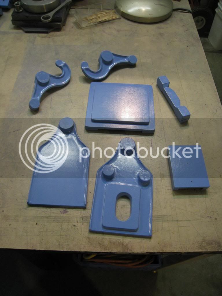
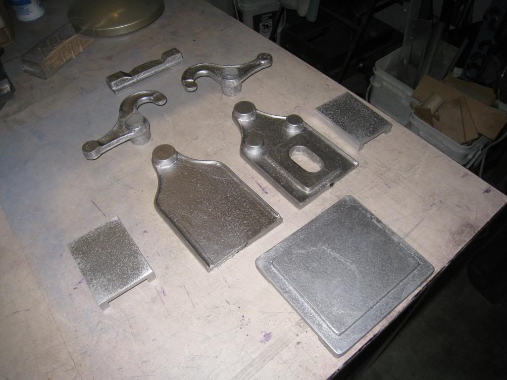
I have the patterns done:
IMG_0645_zps96280e5e.jpg


And I've been running up the charcoal furnace:
IMG_0642_zps360e98d9.jpg


I still need to make a flywheel, but for that I can use the same pattern as the Atkinson cycle engine I made.

By all reports, including Vince Gingery's, this engine is a PITA to get working. Oh well, I guess forewarned is forearmed. I'll be really careful on my cylinder bore to make sure it's parallel and nicely finished.

Stay tuned...
 
Ran the mill over the body castings to square up edges. 12 screws hold everything together. The central cavity of this engine is also a cooling water reservoir. The water circulates around the hot part of the cylinder by flowing through the hole in the front. Once everything else is located and mounted properly I'll take this apart and add some sealant to the joints.


Spent some time working on getting the pivot arms attached. Much time was spent drilling and reaming holes.


Each of the pivot points is a bronze or brass sleeve bearing, so there was some careful measuring for press fits on all of these.


The trickiest thing here is the 6 1/2" diameter shafts, each of which has to be parallel with the other shafts. If you didn't get it right you could end up with a nasty binding problem when you tried to put it together. I'm happy to say that this turns pretty smoothly without any slop. There are a couple of slightly tight points, but nothing I can't take care of in run-in.
 
When I watch videos of this engine running, especially in slow-motion, it never fails to fascinate me, no matter how many times I see it. Absolutely ingenious mechanism. Many years ago, a gent named Brooks Pendergrast retailed the plans for this engine at the old, Leesport-Cabin Fever shows, then Gingery came out with his version. Nice to see this engine being built. Can't wait for the rest of the construction article to unfold...and hope the photos will not be deleted in the future.

I predict that there will be one of these engines in my future.

Frank


EDIT.....Wish some enterprising person would sell the castings for this engine! I'd buy a set in a NY second! I would've tried building this engine long ago, but I have no desire to pour castings, or potentially, immolate myself like some Joan of Arc, in the process. SELL CASTINGS....PLEASE!
 
Wish some enterprising person would sell the castings for this engine!

I know aonemarine is doing some market research for a casting kit, maybe you could convince him. If that doesn't work, I'd hate to see you held back, and I'd like to see the work put into the patterns to be amortized into more than one engine... so perhaps we could work something out.

Jason H.
 
I've been redrawing the Pendergrast drawings in CAD for a member here. (Almost finished G.K.)
I have most of the models/drawings complete, Maybe G.K. will chime in here & we can share the models/drawings
For creating castings.

Jason: Great job!! Your castings are fantastic, this is coming together very nicely!

John
 
I know aonemarine is doing some market research for a casting kit, maybe you could convince him. If that doesn't work, I'd hate to see you held back, and I'd like to see the work put into the patterns to be amortized into more than one engine... so perhaps we could work something out.

Jason H.

So many engines, so little time. Id love to build them all.....
 
I'm looking forward to the rest of the project, and perhaps maybe getting in contact with forum members who might have some extra castings for sale, trade, etc.

I have both the Gingery book and the Pendergrast plans, but have no desire to cut aluminum/steel plate for the frame, and other components, used to build this engine. Besides, the castings, with the radiused moldings around the perimeter of the swinging arms, looks classy.

Sell castings....


Frank
 
There are two wishbone conrods to be made. There is a casting for them, but by the time you've finished whittling away everything that isn't a conrod there are no as-cast surfaces left. You could make them out of 3/4 x 3/4 stock if you had some.

Here's the casting after some squaring up.


Outside dimensions are established, the pin holes are drilled and with a bit of rotary table work the ends are rounded off.


After cutting the piece in two the other ends can also be given the rotary table treatment, and we have two conrods.


And now they can be installed.


No excuses now - I guess I should get started on the piston/cylinder assembly.
 
Getting started with the water jacket that holds the cylinder at the front of the engine. It is made from bits of mild steel tube and plate.


The CI round that will make the cylinder has been turned to OD and test fitted to the water jacket.


Braze away.


Digging out all the CI to form the 1-1/8" cylinder bore.
 
Back
Top