Arduino control for a 3” rotary table

Home Model Engine Machinist Forum

Help Support Home Model Engine Machinist Forum:

This site may earn a commission from merchant affiliate links, including eBay, Amazon, and others.

bmac2

Well-Known Member
Project of the Month Winner
Joined
Aug 16, 2013
Messages
1,033
Reaction score
764
I want to be able to cut the gears, and to do that I needed an indexer or dividing head. I’d looked at a lot of plans for different styles of mechanical indexers and was leaning toward “A Fairly Simple Dividing Head” http://www.deansphotographica.com/machining/projects/divider/dividinghead.html by Dean Williams.

Then I found Chuck Fellows 2012 thread “Electronic Dividing Head using the Arduino” http://www.homemodelenginemachinist.com/showthread.php?t=17896 and thought it looked like a much simpler way to go. As things worked out while looking through the surplus section at Princess Auto I found some Arduinos and shields in with the oversized TV remotes, selfie sticks and other bits of electronic detritus. Armed with my new toys I dug out and dusted off a breadboard and started trying to duplicate Chuck’s controller. Found a schematic for the SainSmart LCD Keypad Shield that Chuck used and after much cursing and searching for libraries I managed to get it to work. Messed around with it for a while but I just didn’t like the button interface and the project want into the corner of the workshop dedicated to UFO’s (Un Finished Objects).

I haven’t done much in the way of programing for many years but I liked the Arduino and ordered “Arduino for Dummies” and started going through the exercises. Back in January while looking around on the internet I found a thread on CNC Zone for a standalone CNC rotary table controller for Sherline. I liked the use of a keypad for enter as well as the 20x4 text display. Downloaded the sketch and after messing around with a few DIY worm gears I had it running but not well and it went back to the UFO corner.


[ame="https://www.youtube.com/watch?v=-hO4id64xDU"]https://www.youtube.com/watch?v=-hO4id64xDU[/ame]

IMG_1225 (Medium).jpg
 
In the end this is what I came up with. The heart of the software is from bpratl at CNC just tweaked to work with the hardware I’m using.

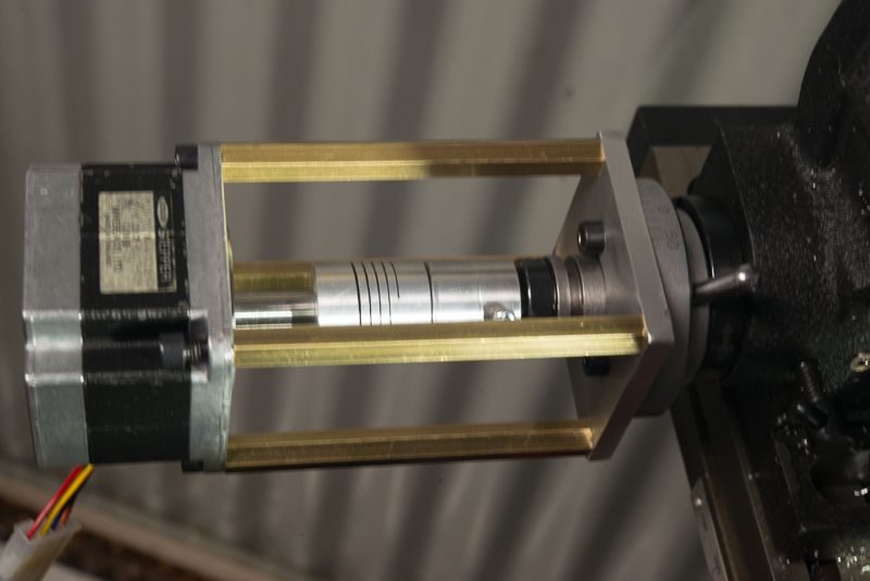
I got things bodgered up with and stepper clamped to my 3” rotary table.


[ame="https://www.youtube.com/watch?v=oubtFZqDJuc"]https://www.youtube.com/watch?v=oubtFZqDJuc[/ame]

/*
4x4 matrix keypad amd a 20 x 4 LCD. Edit StepsPerRotation & TableRatio(# of turns for 360 degrees)
5/2/2015
*/

#include <Wire.h>
#include <LiquidCrystal_I2C.h>
#include <Keypad.h>

const byte ROWS = 4;
const byte COLS = 4;
char keys[ROWS][COLS] = {
{'1','2','3','A'},
{'4','5','6','B'},
{'7','8','9','C'},
{'.','0','#','D'}
};

byte rowPINS[ROWS] = {11,10,9,8};
byte colPINS[COLS] = {7,6,5,4};

Keypad kpd = Keypad(makeKeymap(keys),rowPINS,colPINS, ROWS, COLS);
LiquidCrystal_I2C lcd(0x27,20,4); // set the LCD address to 0x20 for a 16 chars and 2 line display

//setup vars
const int stp = 12; // connect pin 12 to step
const int dir = 13; // connect pin 13 to dir
const int StepsPerRotation = 200; // Set Steps per rotation of stepper
const int TableRatio = 90; // ratio of rotary table
const int Multiplier = (StepsPerRotation * TableRatio)/360; // 200*90=18000/360 = 50
const int stepdelay = 1;
float Degrees = 0; // Degrees from Serial input
float ToMove = 0; // Steps to move
float bob = 0;
int cho = 0;

void setup()
{
lcd.init(); // initialize the lcd
pinMode(stp, OUTPUT);
pinMode(dir, OUTPUT);

// Print welcome message to the LCD.
lcd.backlight();lcd.print("Rotary Table Control");
lcd.setCursor(4,2);lcd.print("bpratl CNC");
lcd.setCursor(3,3);lcd.print("updated 2015");
delay(2000);
lcd.init();
cho = 0;
char key = kpd.getKey();
lcd.print("Enter Selection:");
lcd.setCursor(0,1);lcd.print("Degrees = A");
lcd.setCursor(0,2);lcd.print("Divisions = B");
lcd.setCursor(0,3);lcd.print("JOG = C");
while(cho == 0)
{
key = kpd.getKey();
switch (key)
{
case NO_KEY:
break;
case 'A':
Degrees=getdegrees();
lcd.clear();
cho = 1;
break;
case 'B':
Degrees=getdivisions();
cho=2;
break;
case 'C':
Degrees=getjog();
lcd.clear();
cho=3;
break;
} // end case
} // end while cho=0
} // end setup

void loop() // MAIN LOOP
{
lcd.clear();
char key = kpd.getKey();
bob = 0;
lcd.setCursor(7,0);lcd.print("Total: ");lcd.print(bob,2); // total steps
lcd.setCursor(0,3);lcd.print("FOR=A REV=B X=C");
while(key != 'C') // C will return to start menu
{
lcd.setCursor(0,0);lcd.print(abs(Degrees),2);lcd.print((char)223);
key = kpd.getKey();
if(key == 'A') // FORWARD
{
bob = bob + Degrees;
ToMove = (Degrees*Multiplier);
digitalWrite(dir, LOW);
printadvance();
}
if(key=='B') // REVERSE
{
bob = bob - Degrees;
ToMove = (Degrees*Multiplier);
digitalWrite(dir, HIGH); // pin 13
printadvance();
}
} // end while not C loop
lcd.init();
setup();
} // end main VOID


float getjog()
{
float Degrees = 0;
float num = 0.00;
char key = kpd.getKey();
lcd.clear();
lcd.setCursor(6,0);lcd.print("Jogging");
lcd.setCursor(0,1);lcd.print("A=1 B=10 C=100 Steps");
lcd.setCursor(0,2);lcd.print("Enter Degrees:");lcd.setCursor(0,3);lcd.print("OK = # ");lcd.print((char)60);lcd.print((char)45);lcd.print(" D");

while(key != '#')
{
switch (key)
{
case NO_KEY:
break;
case 'A':
Degrees = 1;
lcd.setCursor(14,2);lcd.print(Degrees);
break;
case 'B':
Degrees = 10;
lcd.setCursor(14,2);lcd.print(Degrees);
break;
case 'C':
Degrees = 100;
lcd.setCursor(14,2);lcd.print(Degrees);
break;
case 'D':
num=0.00;
lcd.setCursor(14,2);lcd.print(" ");
lcd.setCursor(14,2);
break;
}
key = kpd.getKey();
}
return Degrees;
}


float getdivisions()
{
float Degrees = 0;
float num = 0.00;
char key = kpd.getKey();
lcd.clear();
lcd.setCursor(0,1);lcd.print("Enter Division:");lcd.setCursor(0,3);lcd.print("OK = # ");lcd.print((char)60);lcd.print((char)45);lcd.print(" D");
lcd.setCursor(16,1);

while(key != '#')
{
switch (key)
{
case NO_KEY:
break;

case '0': case '1': case '2': case '3': case '4':
case '5': case '6': case '7': case '8': case '9':
num = num * 10 + (key - '0');
lcd.print(key);
break;

case 'D':
num=0.00;
lcd.setCursor(16,1);lcd.print(" ");
lcd.setCursor(16,1);
break;
}
Degrees = 360/num;
key = kpd.getKey();
}
return Degrees; //num;
}


float getdegrees()
{
//int key = 0;
float num = 0.00;
float decimal = 0.00;
float decnum = 0.00;
int counter = 0;
lcd.clear();
//lcd.init();
char key = kpd.getKey();
lcd.setCursor(0,1);lcd.print("Enter Degrees:");lcd.setCursor(0,3);lcd.print("OK = # ");lcd.print((char)60);lcd.print((char)45);lcd.print(" D");
lcd.setCursor(15,1);
bool decOffset = false;

while(key != '#')
{
switch (key)
{
case NO_KEY:
break;

case '.':
if(!decOffset)
{
decOffset = true;
}
lcd.print(key);
break;

case 'D':
num=0.00;
lcd.setCursor(15,1);lcd.print(" ");
lcd.setCursor(15,1);
break;

case '0': case '1': case '2': case '3': case '4':
case '5': case '6': case '7': case '8': case '9':
if(!decOffset)
{
num = num * 10 + (key - '0');
lcd.print(key);
}
else if((decOffset) && (counter <= 1))
{
num = num * 10 + (key - '0');
lcd.print(key);
counter++;
}
break;
} //end case
decnum = num / pow(10, counter);
key = kpd.getKey();
} //end while not #
return decnum;
} // end getdegrees

void printadvance() // print function
{
lcd.setCursor(6,1);lcd.print("Moving");
lcd.setCursor(4,2);lcd.print("Steps ");lcd.print(ToMove,0);
lcd.setCursor(13,0);lcd.print(bob,2);
rotation(ToMove,0);
lcd.setCursor(6,1);lcd.print(" ");
}

void rotation(float tm, int d)
{
for(int i = 0; i < tm; i++)
{
digitalWrite(stp, HIGH);
delay(stepdelay);
digitalWrite(stp, LOW);
delay(stepdelay);
}
}

void software_Reset() // Restarts program from beginning but does not reset the peripherals and registers
{
asm volatile (" jmp 0");
}
 
It was looking pretty good but I got busy with other things and didn’t get back to it until now. The stepper motor is thicker than the rotary table and I didn’t want to modify the table so I made up a mount that it will overhang on the mill table when mounted flat and not get in the way in the vertical position.

Stepper Mount.jpg
 
The mount is pretty simple, the larger end is just drilled and bored to fit the NEMA 17 and the smaller end will be bored to slip over the graduated collar on the rotary table and be held in place with the original screws. The two end plates where center drilled then a shallow notch was milled at a (give or take) 5 deg. angle to help keep the sides aligned during soldering.

Rotary Table 004.jpg


Rotary Table 005.jpg


Rotary Table 006.jpg
 
To hold it together I ran two #4-40 screws through the center joined up with a threaded standoff. This actually worked really well as I could get the parts tightly clamped and gently tap things into alignment. The notches are not at an exact fit so solder should flow, but they keep the sides from sliding out of position.

Rotary Table 007.jpg


Rotary Table 008.jpg
 
This was a great idea, terrible execution moment. I had inadvertently grabbed an aluminum standoff.
Plan B, cleaned it up and this time used a steel standoff. Everything stayed in place during soldering then into the pickle jar.

Rotary Table 009.jpg


Rotary Table 010.jpg


Rotary Table 011.jpg
 
Straight out of the pickling the solder looked to have good penetration so I set it up in the mill and checked that the ends stayed parallel, then drilled and bored through both plates to maintain alignment. Nothing broke so I gave my solder joints a gold star.:thumbup:

Rotary Table 012.jpg


Rotary Table 013.jpg


Rotary Table 014.jpg
 
I had to open up the mounting holes for the stepper one size before the screws would slip in but other than that with the flexible coupler everything was turning freely. I still had the test circuit from my laser engraver set up on a bread board so I plugged it in to check it out. You can tell from the sound in the video that the stepper was not happy with the 5v .2amps that the drivers where set at but it was running smoothly. When I was playing it looked like it would accelerate up to speed then slow down before stopping. At first I thought this might be caused by the low voltage but then the light came on that the engraver uses G-code.

[ame]https://www.youtube.com/watch?v=Gnc6Lcuq-7g&feature=youtu.be[/ame]

Rotary Table 016.jpg


Rotary Table 017.jpg


Rotary Table 018.jpg
 
There’s minimal wiring involved, the serial display only uses +5, Gnd, and 2 analog ports. The stepper driver uses 2 digital ports, one for step and one for direction and the key pad matrix uses 8 digital ports.
The A/B jumper and regulator aren’t necessary if the stepper voltage is 12v or less. I added it in case I end up using a different stepper or want to run the one I have at a higher voltage. In position “A” the DC input goes straight to the Arduino VIN. In position “B” it goes through a LM7809 9v regulator before going to the Arduino. I’m using an old 16v laptop power supply that doesn’t need any extra filtering capacitors.

Rotary Table 002.jpg


Rotary Table 019.jpg
 
The only box I had that would fit was a 200 x 120 x 75mm waterproof plastic project box. I cut down to 50mm because I don’t need the height and this would be a better fit if I ever use it hand held, and to me it just looks better. The display has a slight radius to the corners so I set it up on top of the milling vice (won’t fit in) and cut out the opening with a 1/8” end mill. Flipped it around and cut the slot for the ribbon cable on the keypad, then drilled the holes for the power switch and reset button. With all the cut outs it looks like something off Dr. Who.

Rotary Table 020.jpg


Rotary Table 023.jpg


Rotary Table 024.jpg
 
Mounted the keypad, reset and power switches and epoxied standoffs for the Arduino and the display in place.

Rotary Table 025.jpg
 
Test fit the Arduino and display then drilled the holes for the power jack and the connector for the stepper and got them installed.

Rotary Table 026.jpg


Rotary Table 021.jpg


Rotary Table 029.jpg


Rotary Table 027.jpg


Rotary Table 030.jpg
 
Spliced the connector to the stepper motor wires adding another 9” to the overall length then covered everything with some split loom to protect it

Rotary Table 032.jpg
 
I’ve read dozens of write-ups on setting the current limit on the a4988 stepper drivers and it’s a 50/50 split on the voltage calculation to get it right. What I did was make up a simple cable with one of the 4 leads broken out and connected to a multimeter reading the current. The manufactures spec on this motor is .64 amps so I set to give or take .6 amps.

Stepper Breakout.jpg


Nema 17 .jpg


Current 01.jpg


Current 02.jpg
 
Buttoned up I’m pretty happy with the results. The camera does not do this display justice. It is super clear and readable at most any angle.


[ame]https://www.youtube.com/watch?v=rINnNgQQcXQ&feature=youtu.be[/ame]

Rotary Table 033.jpg


Rotary Table 033a.jpg
 
The shaft on the rotary table has quite a wobble and I’m thinking of replacing the flexible coupler with a spider shaft coupling like this one.

Now I just have to fix the speed control on my Mini-Mill.:fan:

Spider Shaft Coupling.jpg
 
Bob,
Full marks for this job, especially the keypad.
I have been asking for years [ literally ] why someone can't put one of those cheap keypads on instead of the silly 4 buttons.

As regards your coupling don't use a Lovejoy type they are not flexible enough.
Lokk instaed for an Oldham coupling which is the only coupling made that can handle misalignment in two planes.
 
Looks great. You may be able adjust the alignment simply by loosening and tightening stepper mounting screws. Your mount is a bit different to mine, but adjusting the brass rods that are threaded at the table end did the trick.

DSC_5246_zps413f139b.jpg
 
That is a fine bit of work, and a very nicely done log of its building. Excellent post, thank you.
 
When you get to fixing your mini mill controller, I had success by simply re soldering all connections and installing a new speed control pot. It has been solid since then.

I used a simple pot and separate switch as the combined pot/switch looked frail to me for repeated use.

The basic design seems to be OK but the quality control during assembly is the problem.
 
Back
Top