Joachim Steinke
Active Member
- Joined
- Jun 14, 2010
- Messages
- 29
- Reaction score
- 22
Hallo everyone
My first IC engine operates with a sleeve valve, so I wasnt in need of making cam shafts in the past. Now, being busy in the design phase of some new IC projects, I had to think about a suitable way to build my own cam shafts in future.
My plan is to make the shafts from silver steel (ore alternative a special sort of hardenable high strength free cutting steel), harden them after finishing all the turning jobs and then grind the lobes out of the full round blanks. My cam lobes wont get more rise than max. 2mm (0.08in), so grinding without pre forming them on the mill should work well enough.
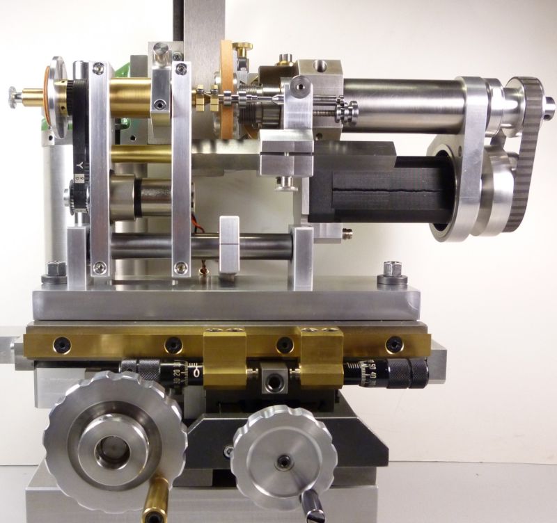
After reading a lot of articles on the web I decided to build a cam grinding attachment that can be mounted on the cross table of my universal tool and cutter grinder. This self designed grinder is only a tiny table top machine, but I build engines in the scale of 1:5 (eventually 1:4) and the dimensions of the required cam shafts are just small enough to fit in the limited work space of my grinder.
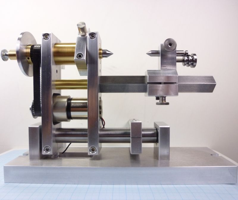
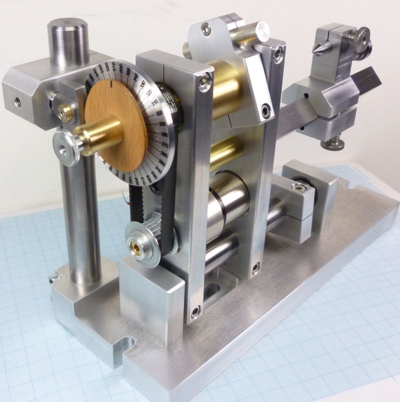
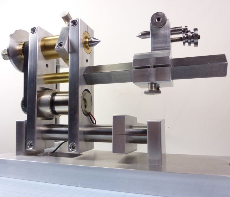
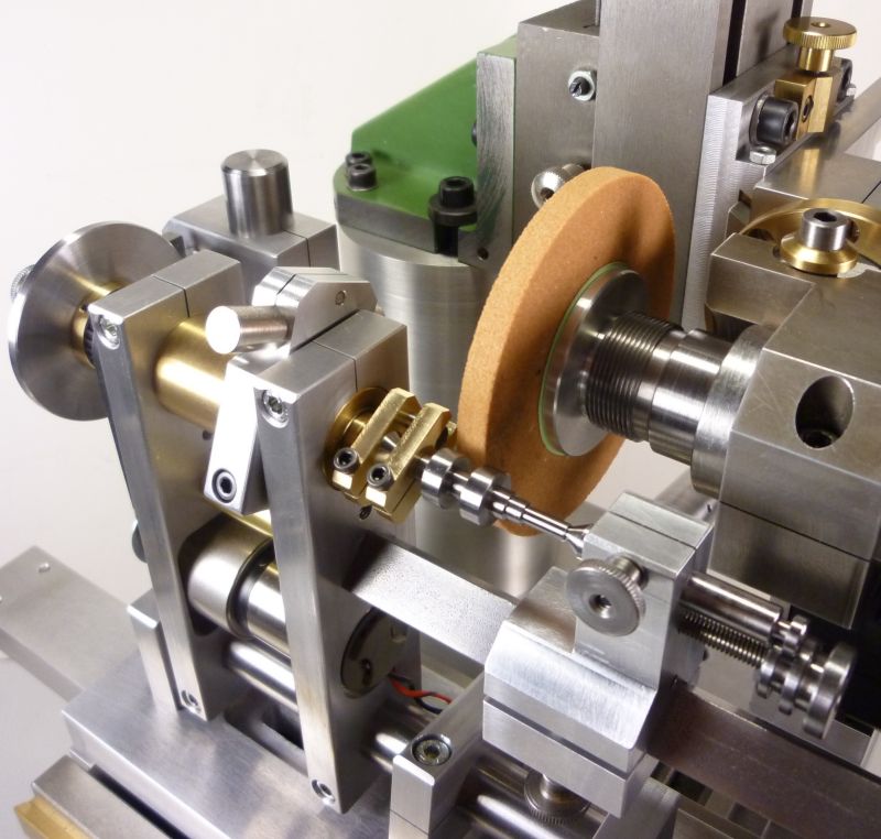
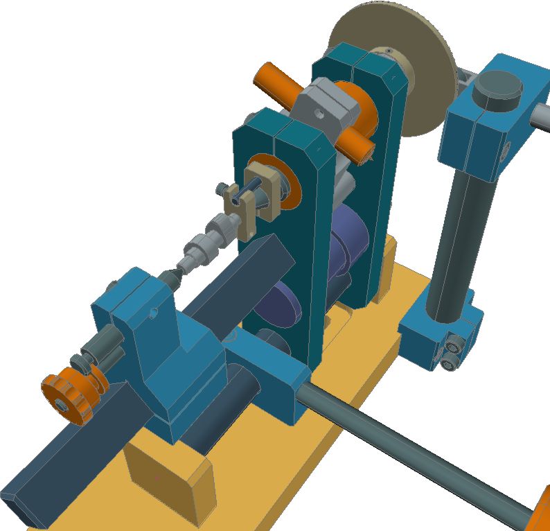
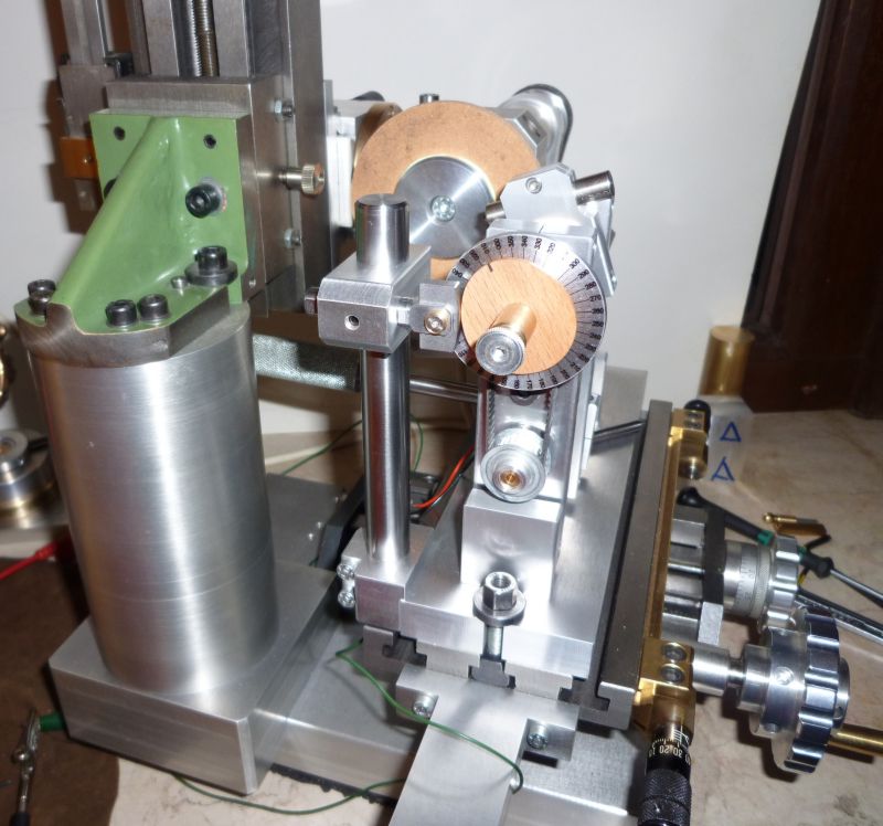
The design is based on a pivoting frame containing a headstock and an extension arm made of 15mm square steel bar which supports a small tailstock. The 8mm headstock spindle is driven by an Escap gear motor using a MXL tooth belt. So the whole construction is much like a very small (and simple) watchmaker lathe.
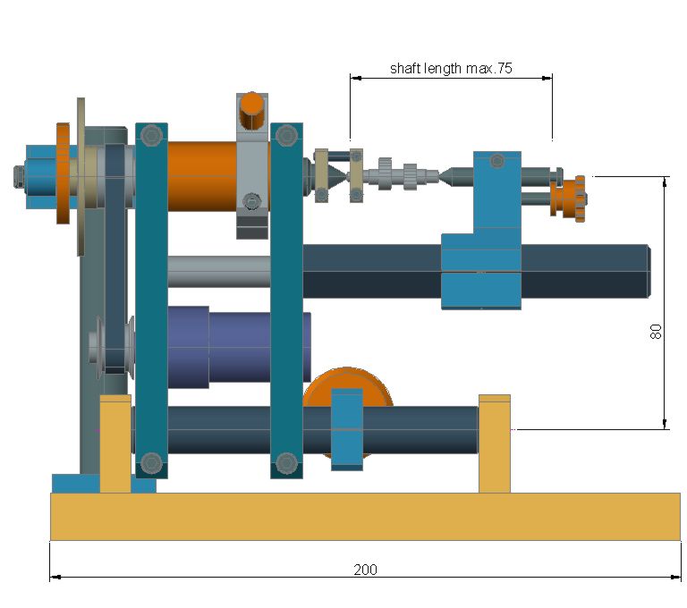
With this layout I have a maximal working length of 75mm (3in) between the cone points. The cam shafts will be fixed by a small lathe dog, so you can take them out temporarily (for measuring ore inspection) and put them back without loosing the rotary position.
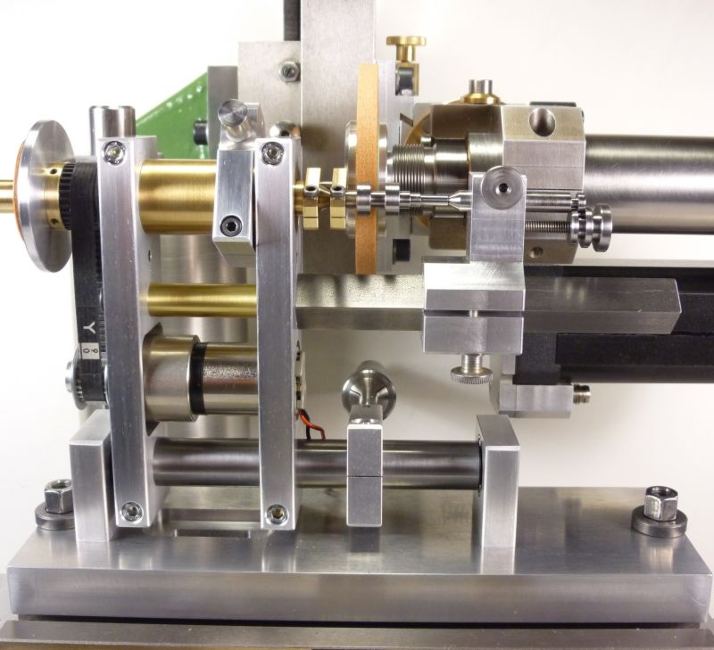
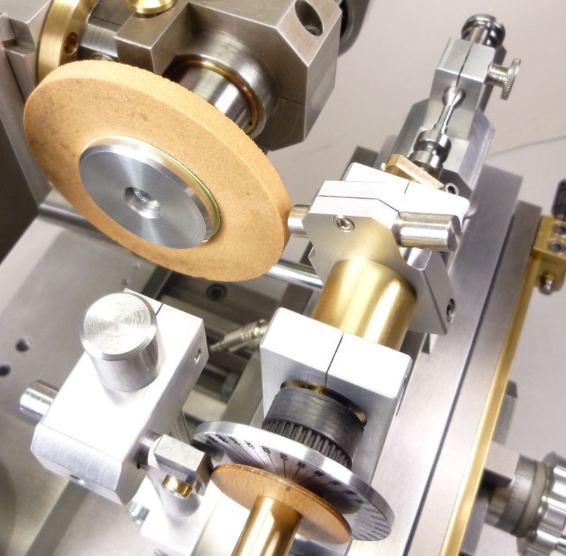
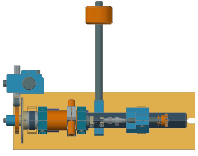
A diamond wheel dresser is placed on the head stocks midsection using an adjustable clamping fixture to assume the needed dressing angle.
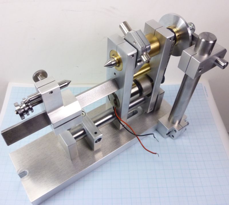
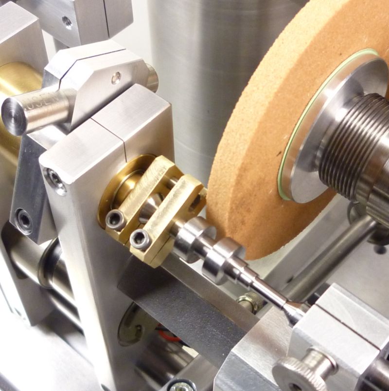
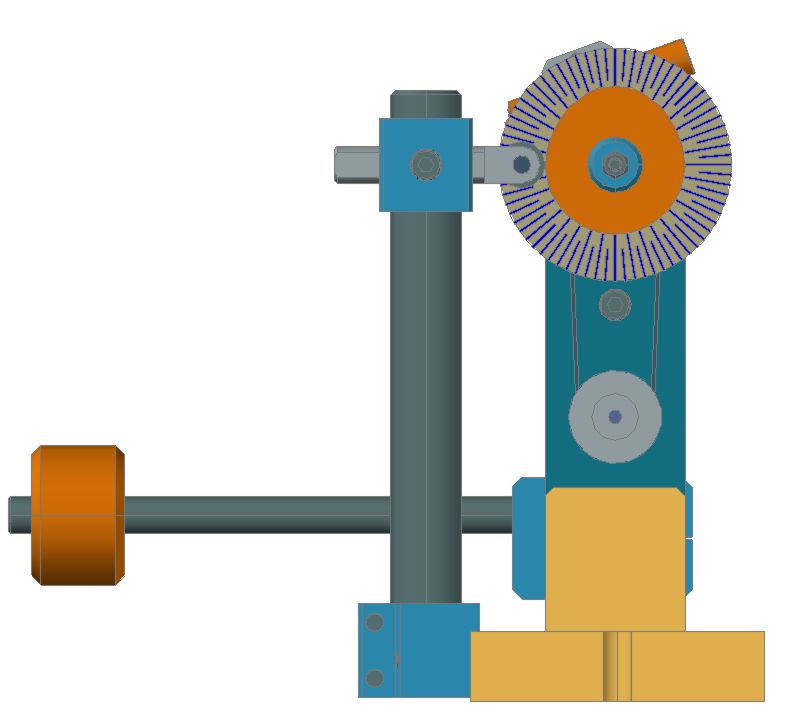
Instead of using a spring load I will use a rocker arm containing an adjustable weight for pressing the master lobe against the detector curve. I think this gives me a better control of the required force as the pressure is also needed for a suitable grinding contact. If it will not work to my wishes I can switch over to a spring system later on.
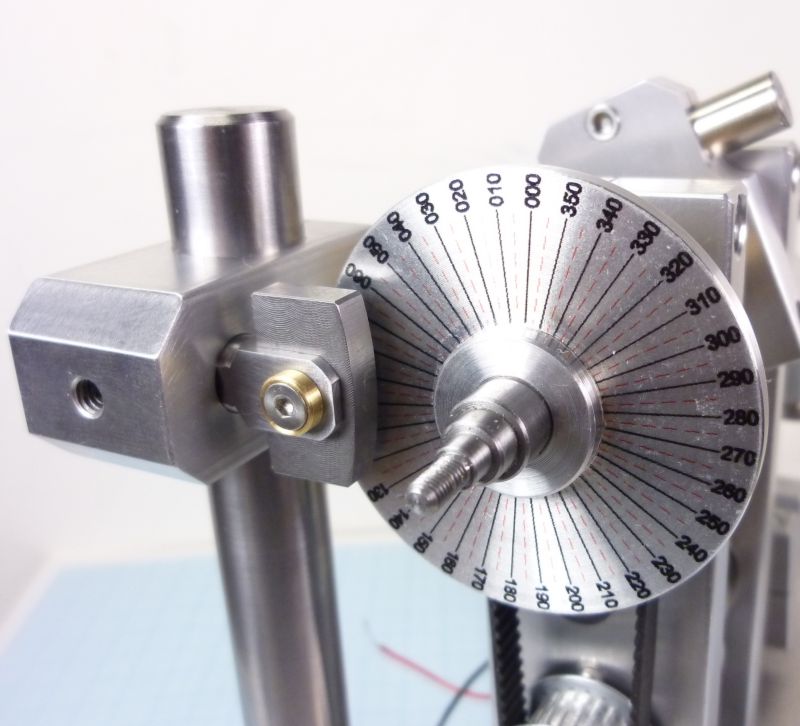
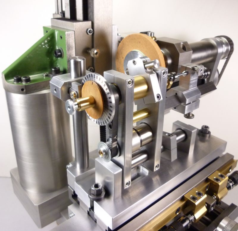
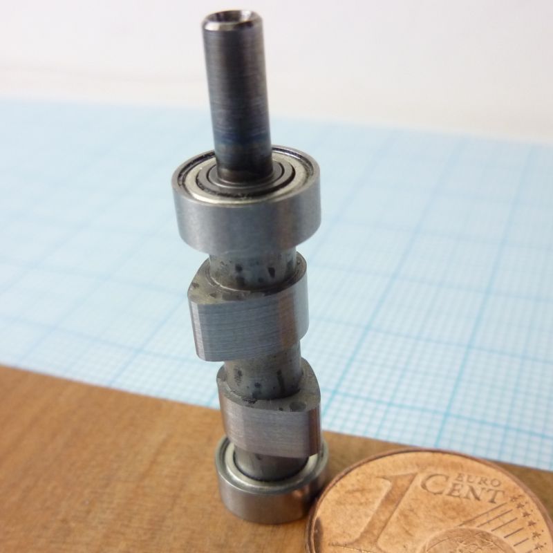
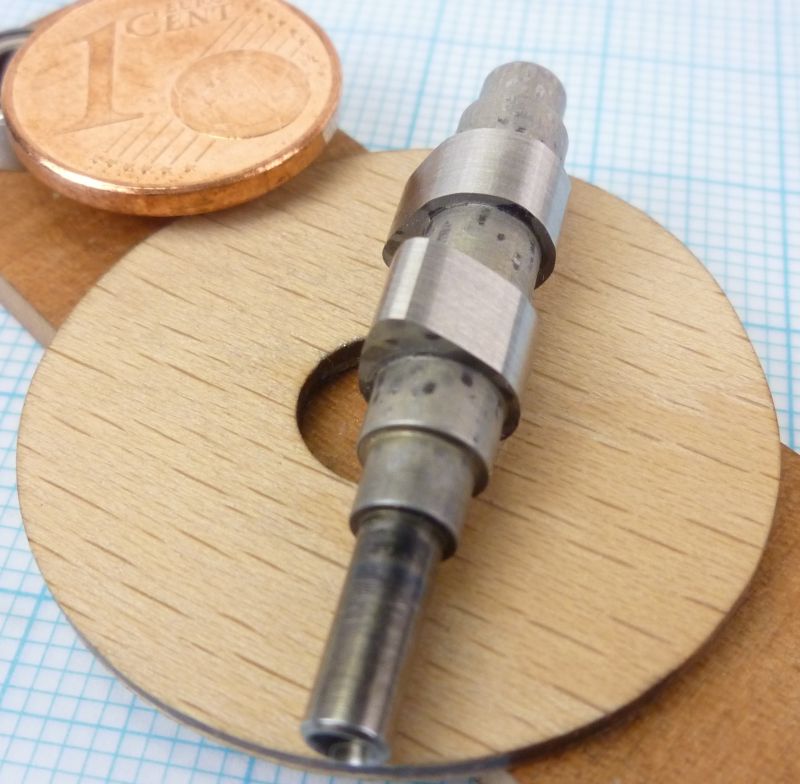
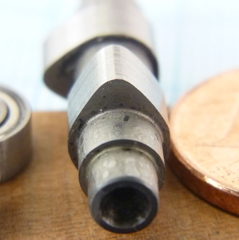
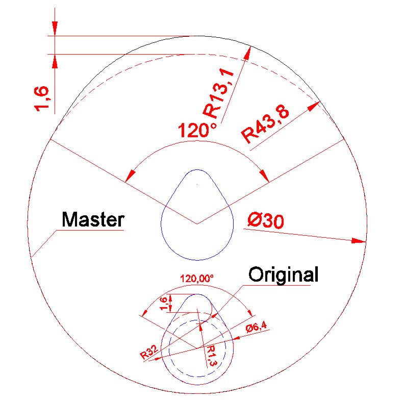
The cam shape is copied from a master lobe which is mounted on the left side in front of a division plate. With this plate I can adjust the offset on multiple lobed cam shafts.
Normally I will use a master with the same lobe rise as the finished product but with a greater main diameter, so this will be no lobe scaling system. The masters can be done in the common way on the milling machine from thicker brass sheet for example, but I think I will make them from 4mm laminate board on my CNC router.
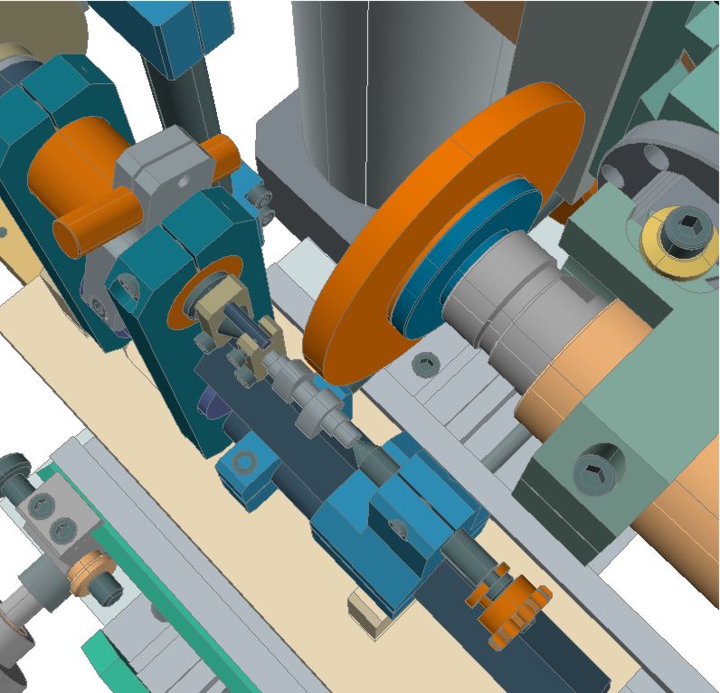
Instead of the ball bearing as a cam follower I use a curve in the diameter of the grinding wheel now, the sampling error of such a small roll is too large which undercuts the side flanks besides the lobe tip.
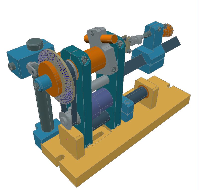
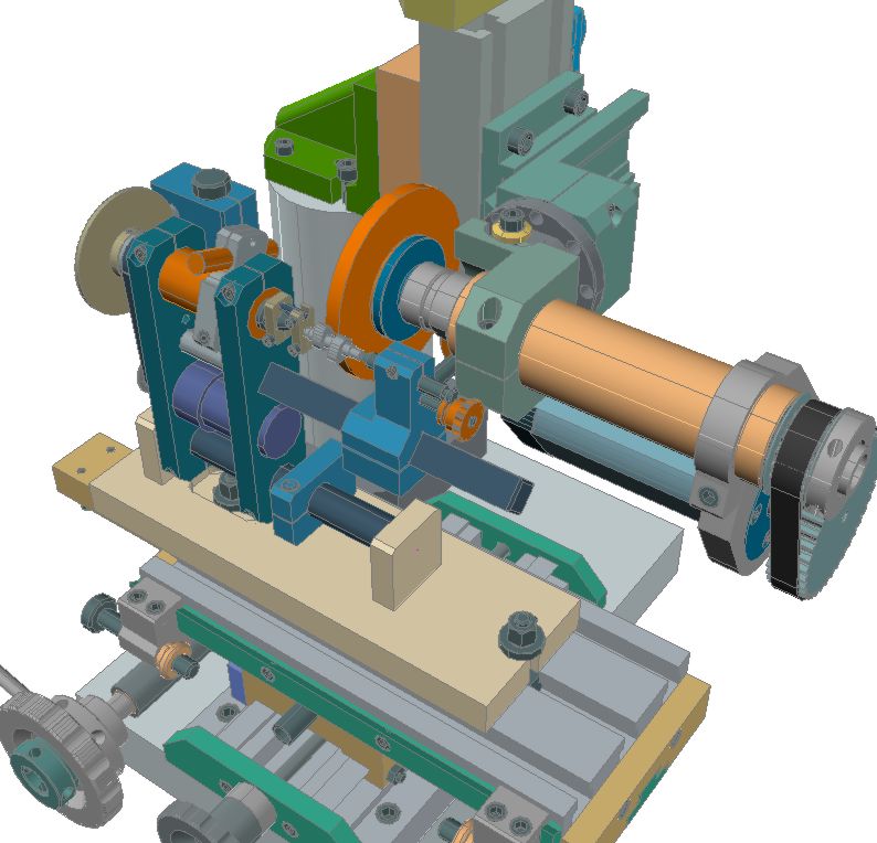
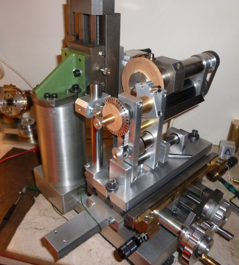
And here some impressions how the fixture fits on my grinding machine:
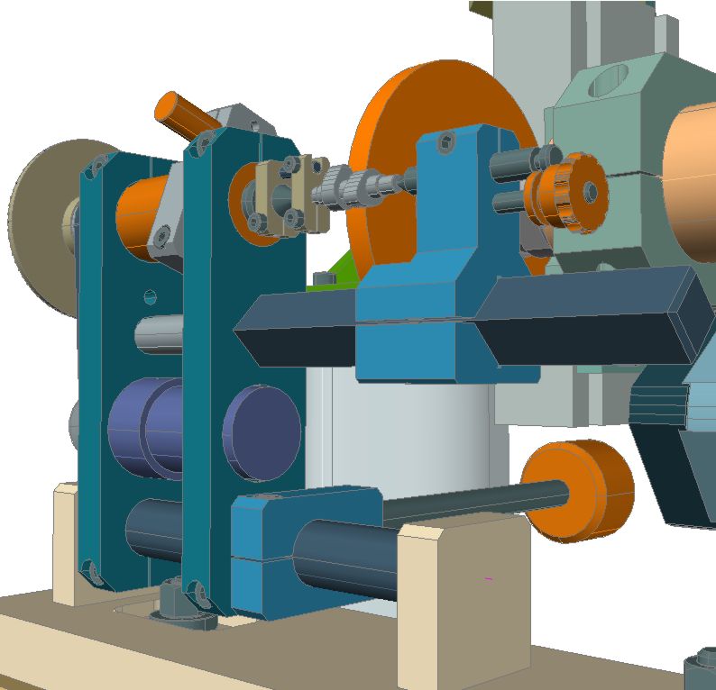
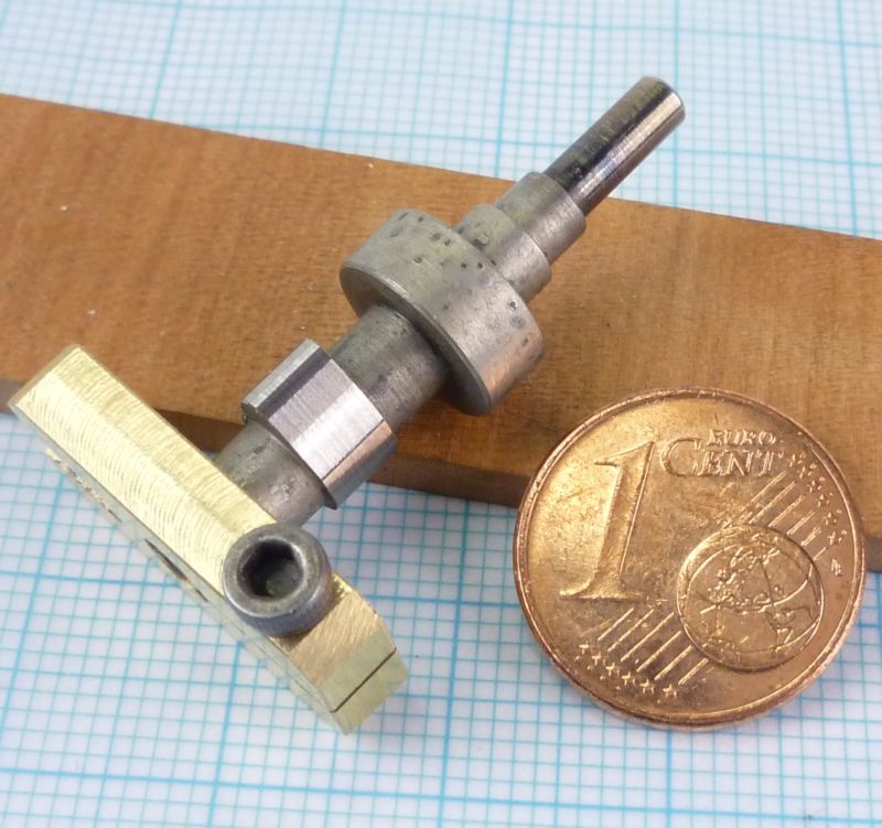
Sadly Im not able to report of first grinding experiences because the fixture is not finished yet. But I started working on it some days ago, as you can see on the first rough pictures (poor quality) I could take this evening:
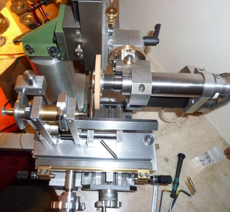
So the tailstock is the last major component to build and I will continuo this report in the next days and hope to come back with some good results on a first test cam shaft ..ha ha ha .
Achim
My first IC engine operates with a sleeve valve, so I wasnt in need of making cam shafts in the past. Now, being busy in the design phase of some new IC projects, I had to think about a suitable way to build my own cam shafts in future.
My plan is to make the shafts from silver steel (ore alternative a special sort of hardenable high strength free cutting steel), harden them after finishing all the turning jobs and then grind the lobes out of the full round blanks. My cam lobes wont get more rise than max. 2mm (0.08in), so grinding without pre forming them on the mill should work well enough.
After reading a lot of articles on the web I decided to build a cam grinding attachment that can be mounted on the cross table of my universal tool and cutter grinder. This self designed grinder is only a tiny table top machine, but I build engines in the scale of 1:5 (eventually 1:4) and the dimensions of the required cam shafts are just small enough to fit in the limited work space of my grinder.
The design is based on a pivoting frame containing a headstock and an extension arm made of 15mm square steel bar which supports a small tailstock. The 8mm headstock spindle is driven by an Escap gear motor using a MXL tooth belt. So the whole construction is much like a very small (and simple) watchmaker lathe.
With this layout I have a maximal working length of 75mm (3in) between the cone points. The cam shafts will be fixed by a small lathe dog, so you can take them out temporarily (for measuring ore inspection) and put them back without loosing the rotary position.
A diamond wheel dresser is placed on the head stocks midsection using an adjustable clamping fixture to assume the needed dressing angle.
Instead of using a spring load I will use a rocker arm containing an adjustable weight for pressing the master lobe against the detector curve. I think this gives me a better control of the required force as the pressure is also needed for a suitable grinding contact. If it will not work to my wishes I can switch over to a spring system later on.
The cam shape is copied from a master lobe which is mounted on the left side in front of a division plate. With this plate I can adjust the offset on multiple lobed cam shafts.
Normally I will use a master with the same lobe rise as the finished product but with a greater main diameter, so this will be no lobe scaling system. The masters can be done in the common way on the milling machine from thicker brass sheet for example, but I think I will make them from 4mm laminate board on my CNC router.
Instead of the ball bearing as a cam follower I use a curve in the diameter of the grinding wheel now, the sampling error of such a small roll is too large which undercuts the side flanks besides the lobe tip.
And here some impressions how the fixture fits on my grinding machine:
Sadly Im not able to report of first grinding experiences because the fixture is not finished yet. But I started working on it some days ago, as you can see on the first rough pictures (poor quality) I could take this evening:
So the tailstock is the last major component to build and I will continuo this report in the next days and hope to come back with some good results on a first test cam shaft ..ha ha ha .
Achim