Another Beam Engine

Home Model Engine Machinist Forum

Help Support Home Model Engine Machinist Forum:

This site may earn a commission from merchant affiliate links, including eBay, Amazon, and others.
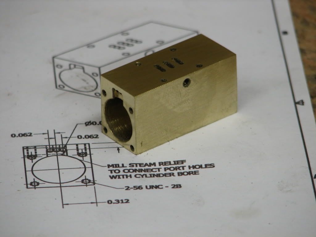
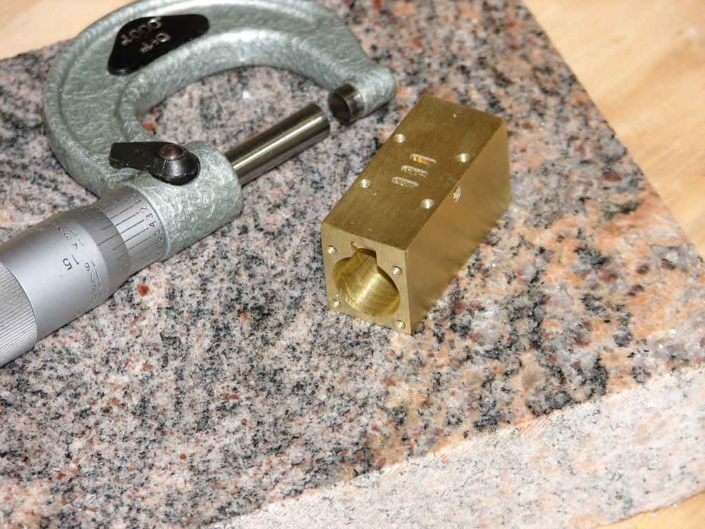
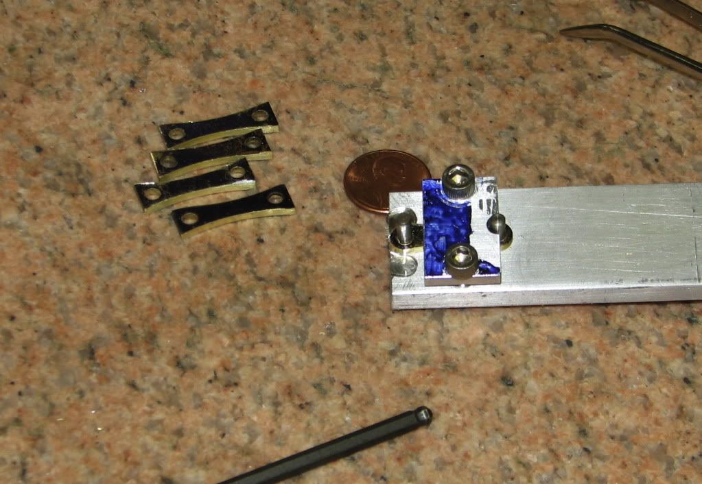
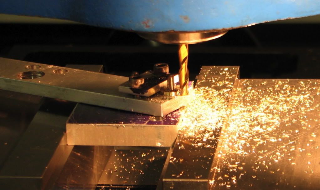
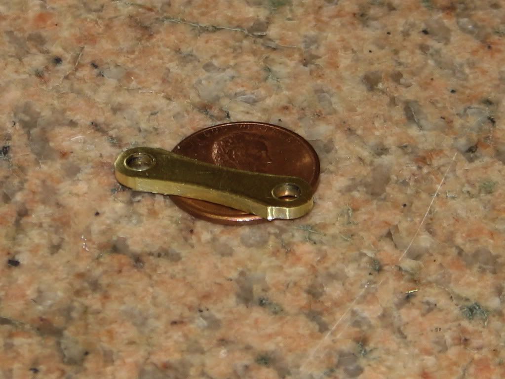
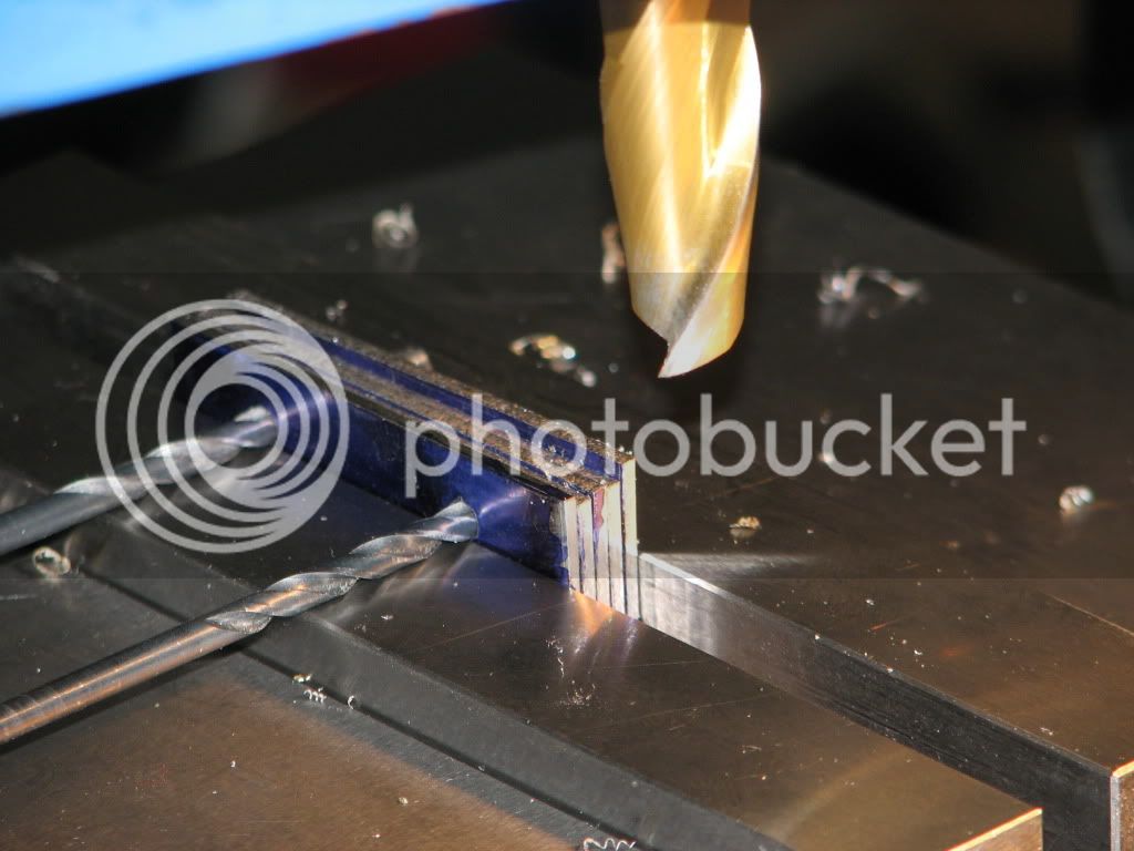
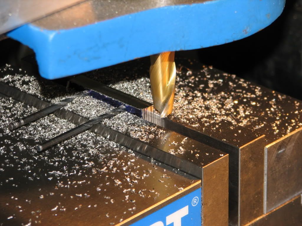
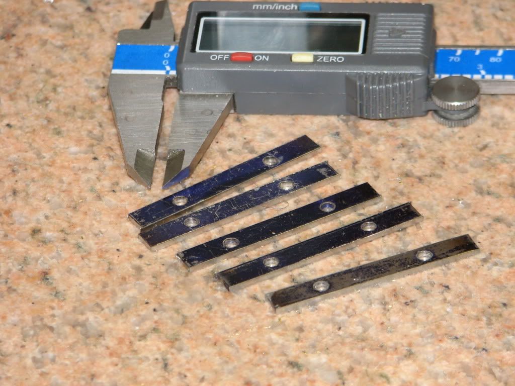
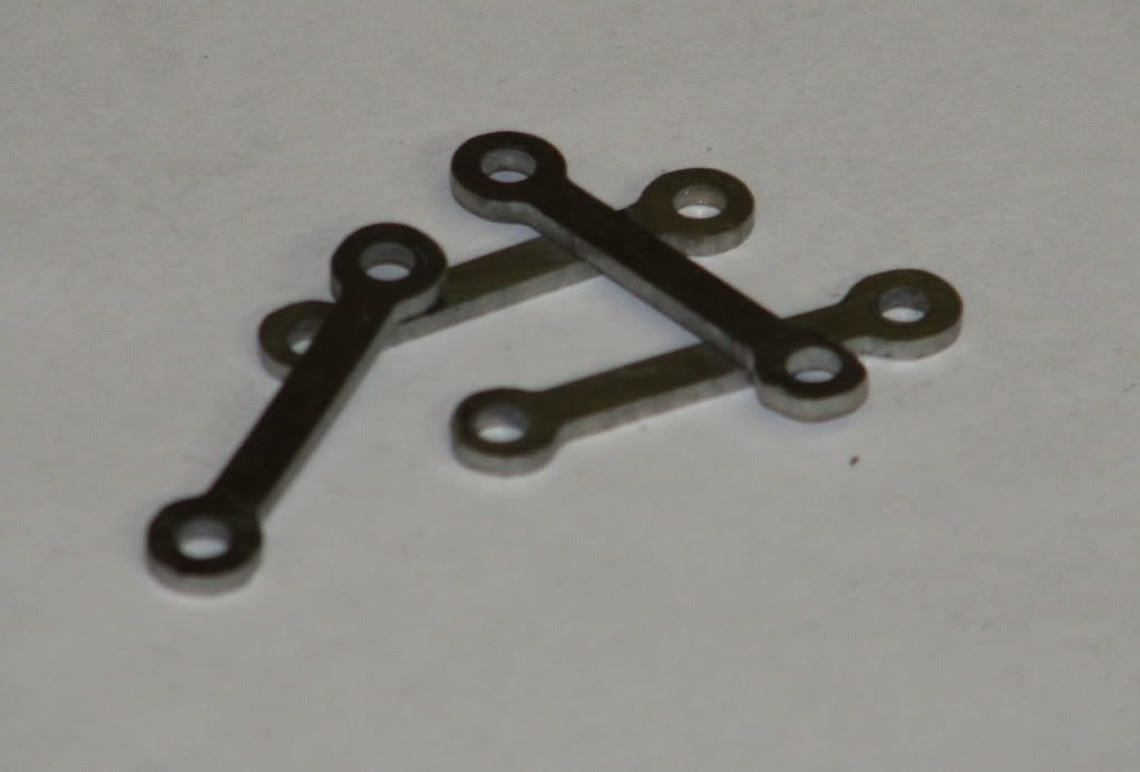
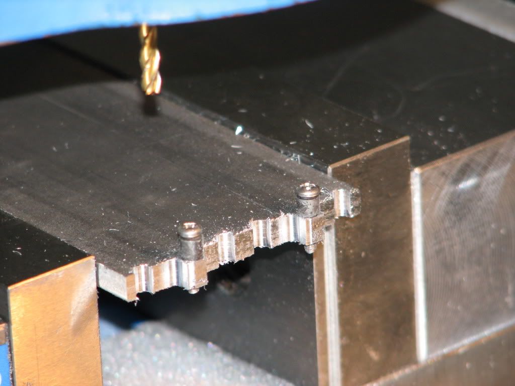
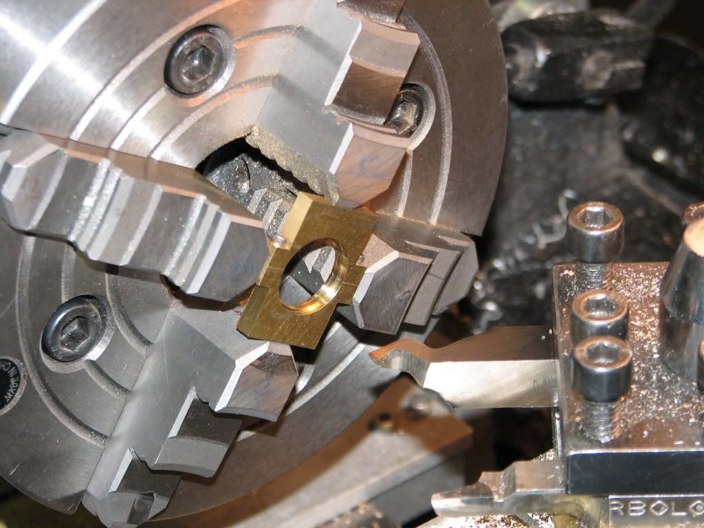
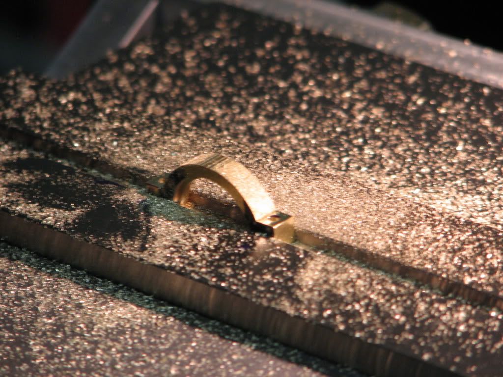
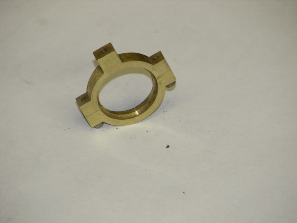
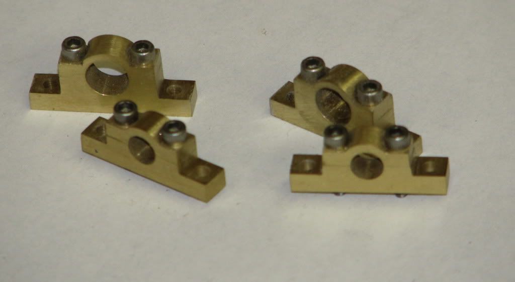
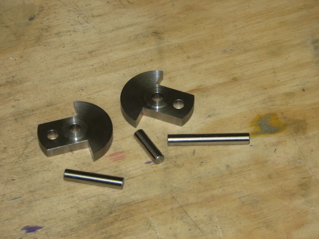
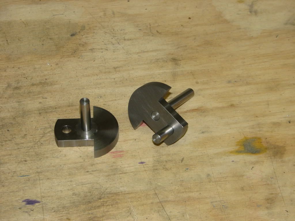
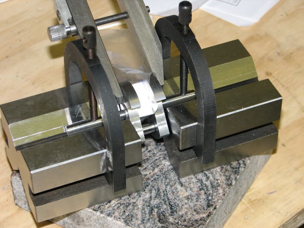
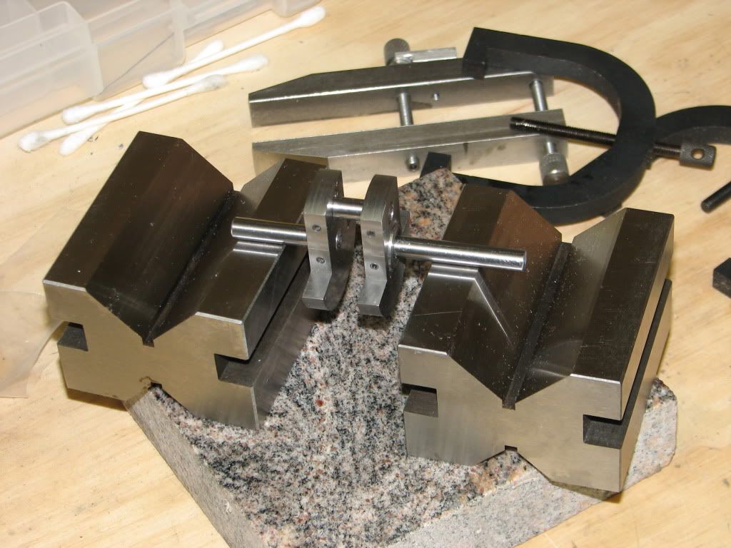
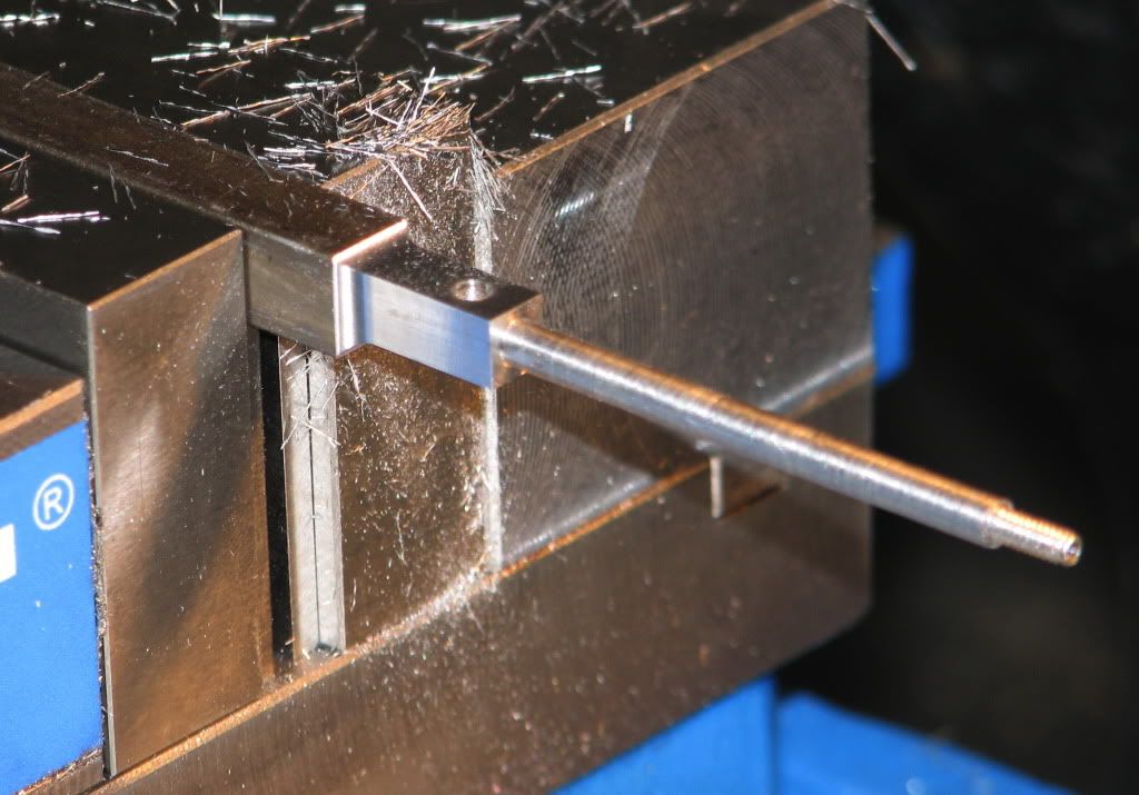
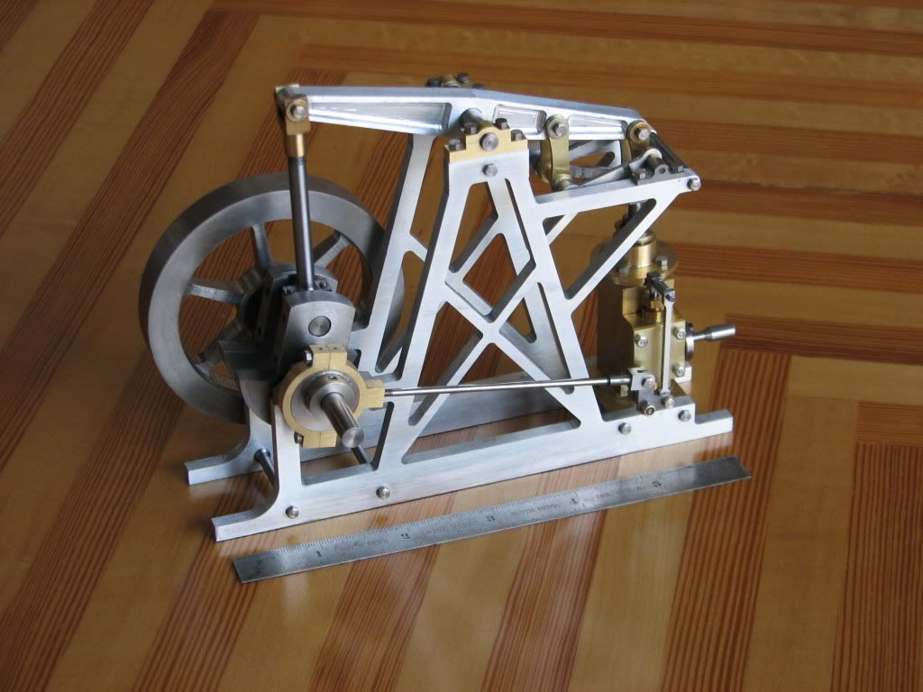
Hi,this is looking good Tux,I built my crankshaft up,locktiteing the shafts to the webs and setting them in a pair of matching v-blocks till set then pinning,came out ok,I didn't fancy silversoldering as i try to keep away from heating things up if possible.
Don
 
Don

Thanks for your input. I have decided to use your method for the crankshaft. The decision is based both on your input and on the description of the crankshafts on MB's Farm Style Engines thread. Besides it is a good excuse to get a pair of matched v-blocks.

Eric
 
I can not believe how long it has been since I have updated this build log.

I have had limited time to work on this build and have used it to machine not to document this build. I have taken some photos along the way. I will not work to catch up. I will not present the progress is strict chronological order but will group related parts.

Where we left off is had just scrapped the cylinder due to placing holes on the wrong face of the part. The next attempt got all of the holes in the right places. Unfortunately the center bore was not clean and slightly tapered. I attempted to re bore the part but without any nluck. I ended up scrapping cylinder 2

cylinder_2_scrap.jpg


After buying some more brass I tried a third time. This one came out much better. I got all of the holes in the proper places and I drilled undersized and reamed the center bore to 1/2"

cylinder_3.jpg


To be continued ....

Eric
 
Next the parallel links. I started by drilling holes in a strip of brass. I drilled 5 sets of holes in case I had to scrap a part.

parallel_link_3.jpg


I separated the parts with a jewelers saw and then stacked the parts to use a boring head to make the side concave.

parallel_line_4.jpg


A small fixture was made to round the ends.

parallel_link_6.jpg

parallel_link_7.jpg


I must have has something slightly off in my setup as can be seen the this photo.

parallel_link_8.jpg


I recovered as best I could with a file. The results are not perfect but very functional.

More to follow ....

Eric
 
And another installment in my catchup

This time the grounding links. Again I started by drilling 5 sets of holes in a strip of stainless. I used a hack saw to separate this parts. The parts were aligned using a pair of drills and the edges squared up and strips milled to width.

grounding_link_1.jpg

grounding_link_2.jpg

grounding_link_3.jpg


I purposely left the strips long so that I would have more to clamp to for the next operation which was to cut a flat recess on each side. I must not have taken any photos of that operation. The ends were shortened and rounded (partly on the mill and partly by hand. In the process I had one fall out. Here is the final results.

grounding_link_4.jpg


Still more to follow ...

Eric
 
Next the grounding link mounting blocks. Here I started by drilling and tapping the 2-25 holes. Next I milled close to the top profile and at the ends. I used filing buttons to help guide the milling.

grounding_link_blocks_1.jpg


I used the mill to separate the blocks from the parent stock. Here are the blocks as they came off the mill.

grounding_link_blocks_2.jpg


After some cleanup with file and sandpaper and drilling the mounting holes here is the final result.

grounding_link_blocks_3.jpg


To be continued

Eric
 
Next the eccentric and eccentric strap.

The eccentric was a simple turning / offset turning part. I deviated from the plans by using steel for the eccentric and brass for the strap. Since this photo was taken I have replaced the 4-40 set screws (grub screws) with shorter screws.

eccentric.jpg


For the eccentric strap I started with two identical pieces of brass. I milled steps on the sides and drilled and tapped to holed the parts together. I drilled and bored the center hole. I then ground a special tool so that I could turn the step on each side of the strap without removing the part form the 4-jaw chuck. The tool can be seen in this photo.

eccentric_strap_1.jpg


I used the mill to get close to the finished radius as shown here. After getting everything setup I moved the part in the x direction a few mills and lowered the quill to the proper depth and made a cut in the y direction. This was repeated and repeated and repeated... Without the radius function on the DRO I would have had to find another way.

eccentric_strap_2.jpg


The other half of the strap was done in the same way. Files and sandpaper were used to smooth the steps left by the mill to yield this.

eccentric_strap_3.jpg


The same basic method was used to make the bearing blocks shown here except the support hole was just drilled and reamed.

berring_blocks.jpg


That is all for today. I am getting close to caught up

Eric
 
Just two more posts and I will up to date.

The next part up is the crankshaft. I decided to go with a built up crank using drill rod and turned throws. I started with these parts

crankshaft_1.jpg


crankshaft_2.jpg


I milled a scrap of aluminum to 0.372" thick to use as a spacer. A piece of drill rod was clamped in the v-blocks and the blocks attached to a small piece of granite using CA adhesive (aka crazy glue). I assembled the parts using Loctite 609 retaining compound and the spacer block wrapped in plastic as shown here. The plastic was to make sure the spacer did not become bonded to the crankshaft assembly.

crankshaft_3.jpg


After a full 24 hours for the retaining compound to set, I removed the assembly from the v-blocks. Next I drilled through the throws and drill rod and pressed in 3/32 roll pins.

crankshaft_4.jpg


To be continued

Eric
 
Just a few more parts and I will be up to date.

For the piston rod I stated with square stock. After centering the stock in the 4-jaw I turned the round parts and threaded the end.

Next over to the mill. I clamped the stock with the turned part extending out the side of the vise. After finding the center of the shaft I milled two sides of the square end. Rotate 90 degrees and repeat plus drill and ream the hole.

piston_rod_1.jpg


The mill was used to separate the part from the stock. Hand filing and a little sandpaper and the part was finished.

piston_rod_2.jpg


I have also completed several other small parts, some of them are shown here.

more_small_parts.jpg


I am currently in the process of assembling the engine and find that there are a few parts missing from the drawing package. I have figured out what I need to make to complete the assembly. I hope to have it assembled this weekend or early next week.

Thanks for checking in

Eric
 
I have finished the last few small parts and assembled the engine. In the assembly process I realized that I needed to trim the head height of some of the screws for clearance. Also there were a couple of places where the fit between parts was a little tight. Once those were resolved I chucked the end of the crankshaft in a drill and ran the engine from the drill for a few minutes to get everything running smoothly.

After jury rigging an air connection I tried to run the engine. At first it would move a fraction of a revolution and stop. I adjusted the eccentric and valve linkage and tightened the fly wheel screws and it started to run well. Here is a photo of the assembled engine

BeamEngine1.jpg


I need to get my wife to make a wooden base for the engine (she is the woodworker in the family). I also need to disassemble the frame so that I can make provisions for mounting to the base. While it is disassembled there are a couple of places where I want to do a little more clean up. In a few days I will post some more photos plus a video of the engine running

Thanks for following along.

Eric
 
That is a very nice engine build,
going through your build thread, makes it more appreciative of seeing the final results, a lot of work and ingenuity went into the build, and it shows greatly, your build thread is very inspirational, with good techniques.

Keep up the great work.
 
hobby

Thanks for the comments. It is always nice to know that others get something form what I present here.

Now on to the next project

Eric
 
Back
Top