Another Beam Engine

Home Model Engine Machinist Forum

Help Support Home Model Engine Machinist Forum:

This site may earn a commission from merchant affiliate links, including eBay, Amazon, and others.

TuxMan

Well-Known Member
Joined
Jul 10, 2010
Messages
66
Reaction score
3
Location
Tuxedo NY
Well after some time off for a short vacation, time spent adding a DRO to my mill and a few side projects I got started on my next (second) engine. For this project I have selected Gerry's Beam Engine. I selected this partly because a number of parts are on a smaller scale than on my first engine and I expect this will force me to improve my skills. I do not expect to follow the plans exactly. I will be making some changes to suite my tastes and tooling.

I will not document every little detail of the build but will post on parts that I think are more interesting or that I find difficult. Please jump in and offer suggestions on better or just different ways of doing things. I want to learn!!!

Without further introduction lets start the project.

I decided to start with the fly wheel partly because I had the material on hand and did not need to wait for my metal order.

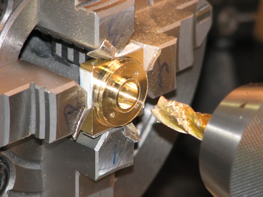
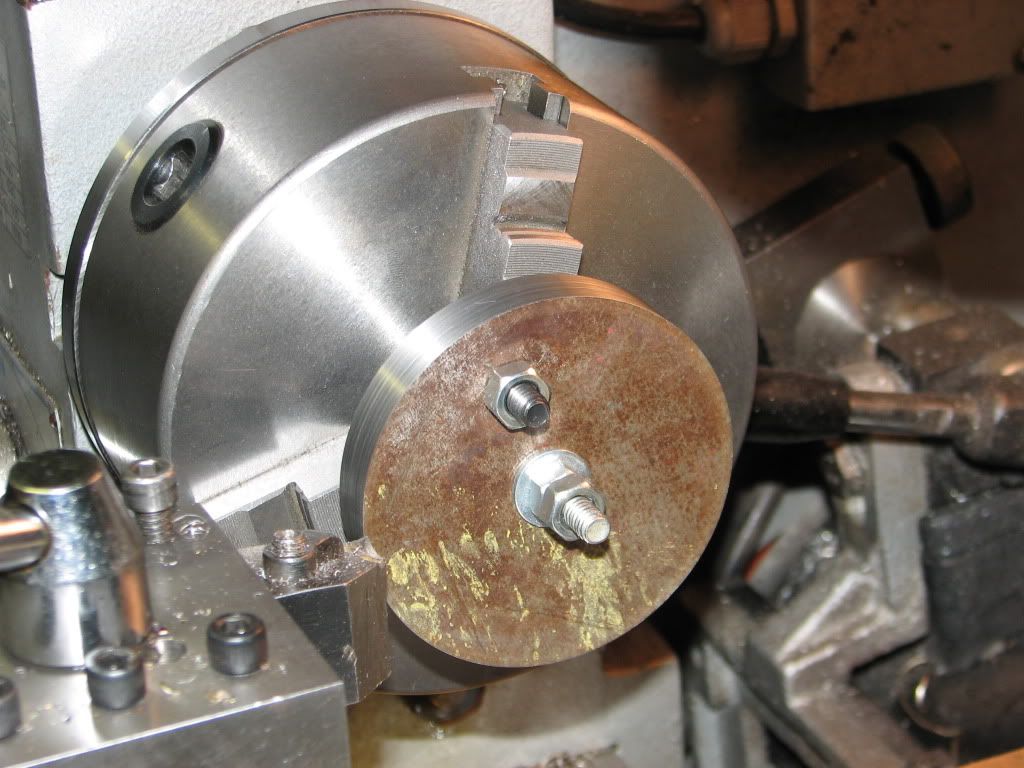
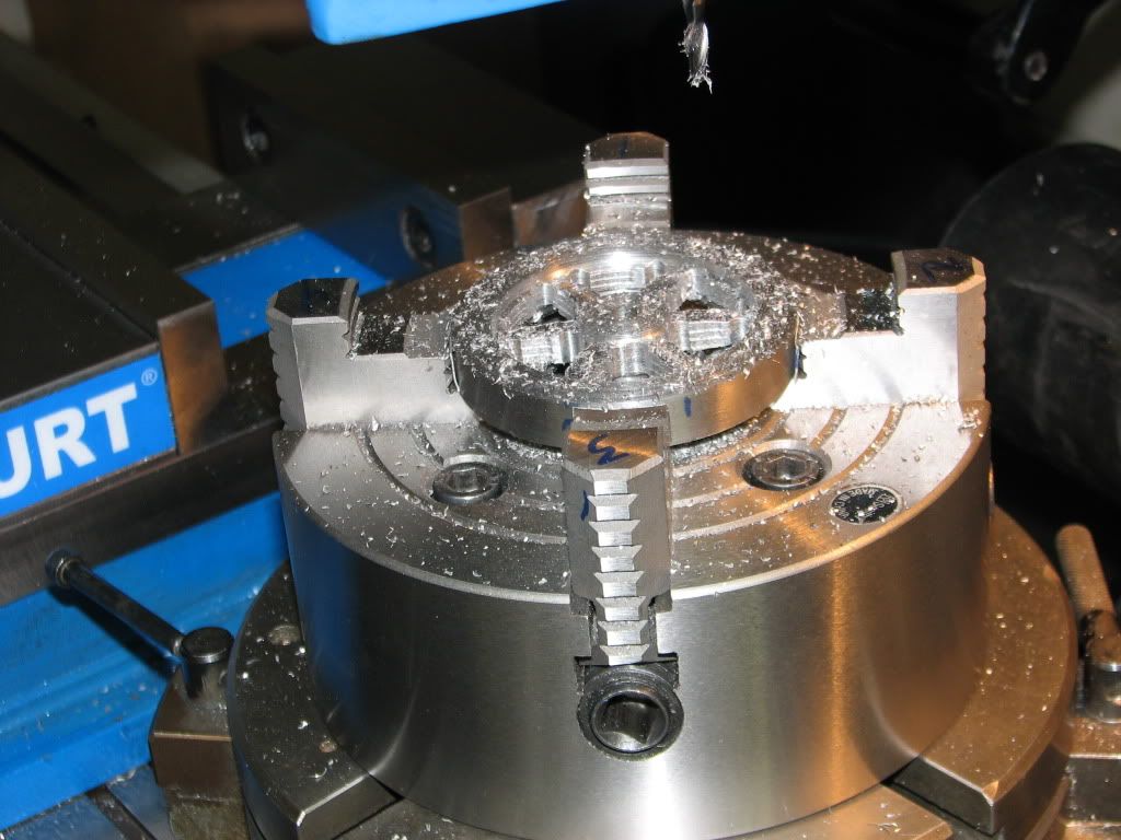
I started by cutting an octagon form some 1/2 inch mystery steel plate. I drilled a hole in the center that was a close fit for a 1/4 inch bolt plus another 1/4 inch hole in the area that will be removed for the spokes. With a 1/4-20 bolt in the jaws of my chuck with the head of the bolt against the inside of the jaws and a socket head cap screw and nut in the second hole to function as a drive dog I mounted the plate as shown below.

flywheel1.jpg


I found that light cuts with a carbide insert tool worked better than the HSS tool shown above.

flywheel2.jpg


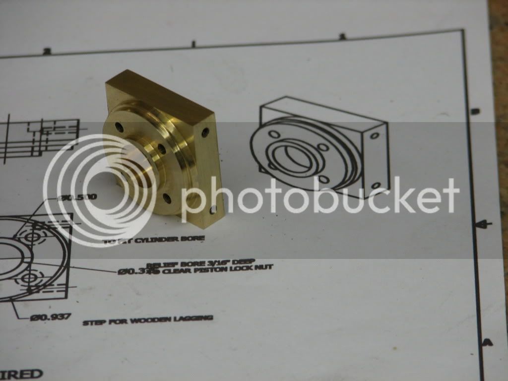
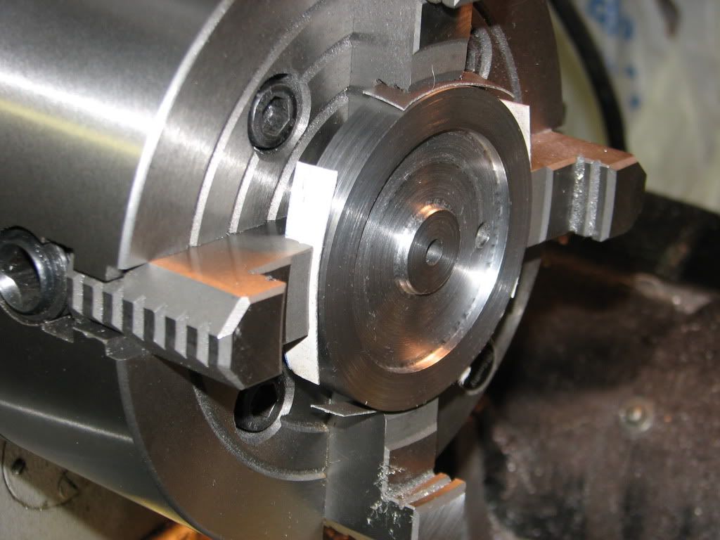
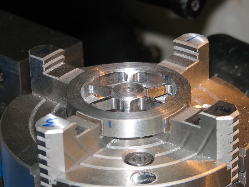
After turning the outside to the required 3 inch diameter is switched to the 4-jaw and faced the part and turned the recess that will be the spokes. I am not real happy with the surface finish.

flywheel3.jpg


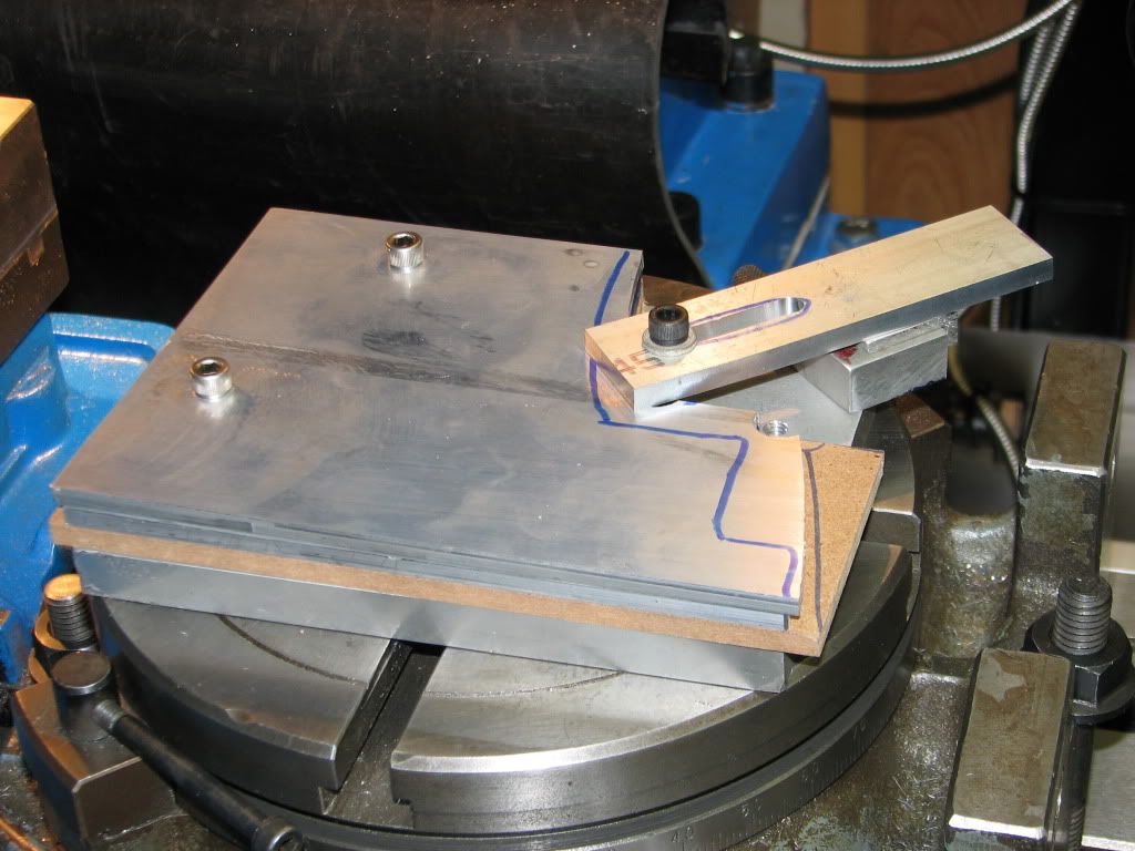
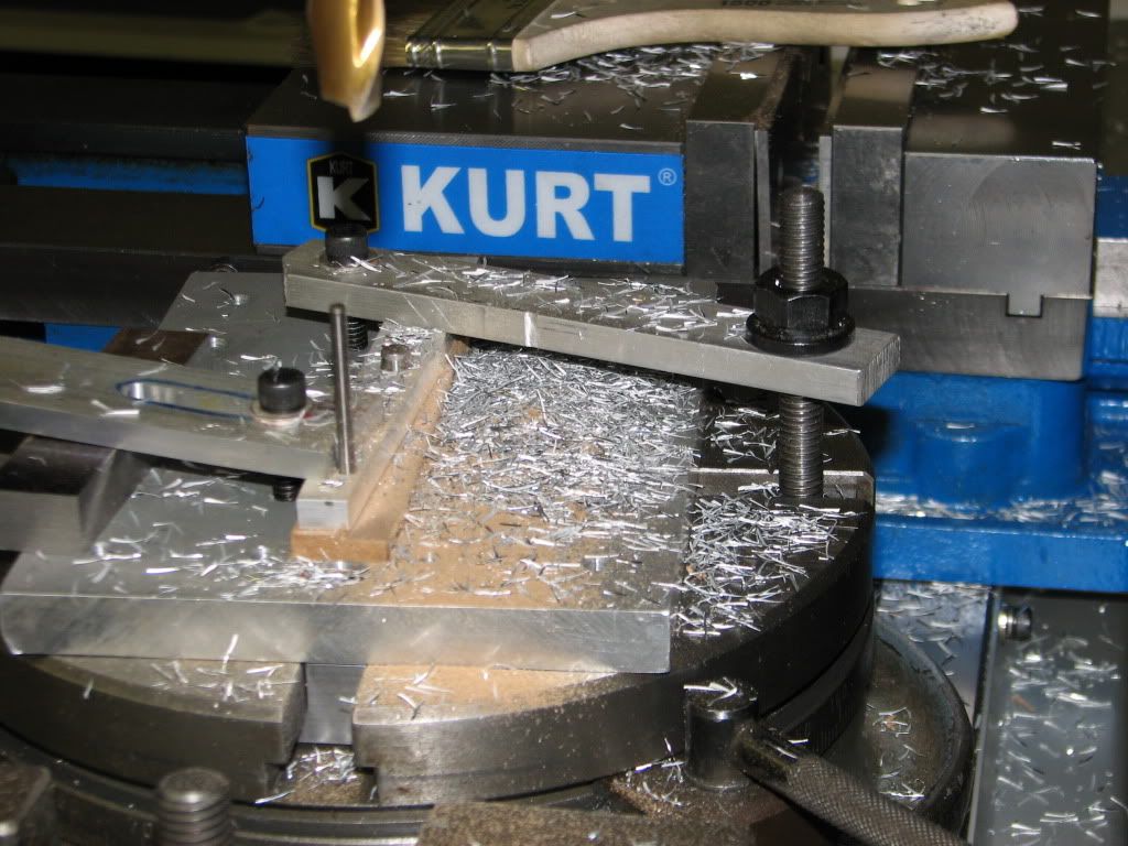
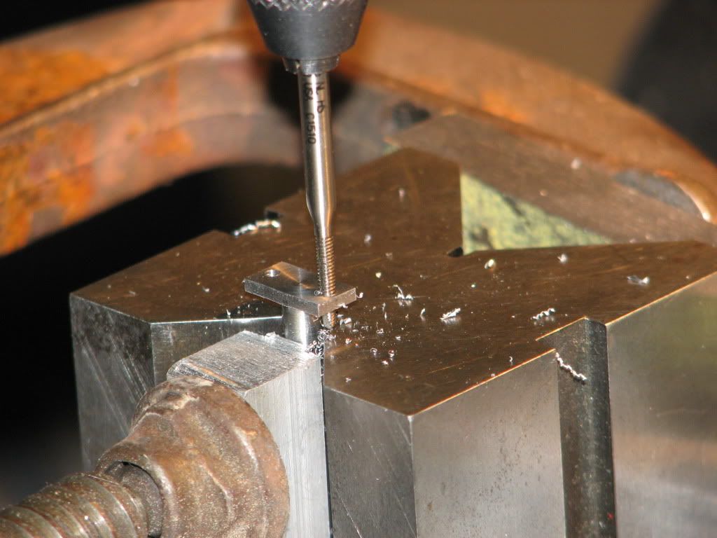
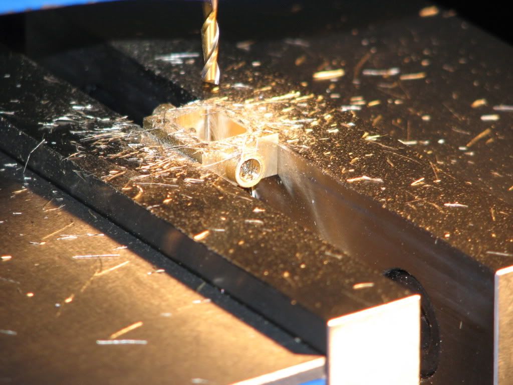
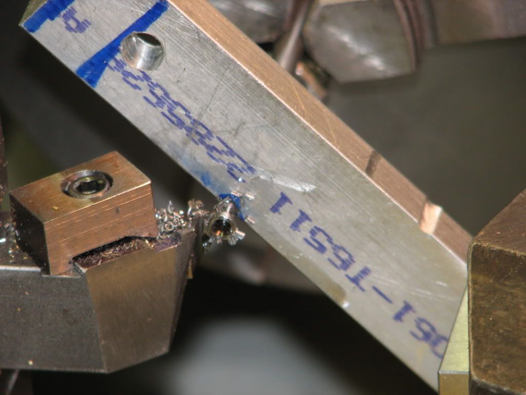
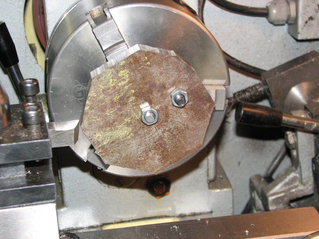
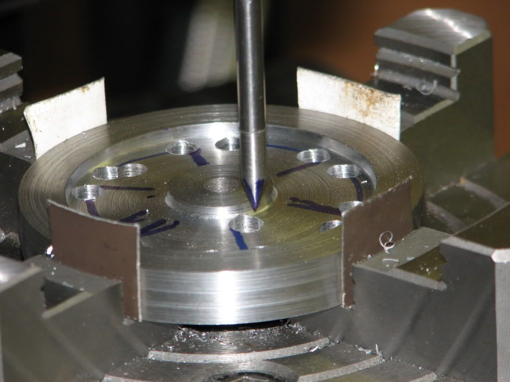
Next over to the mill with the 4-jaw mounted on the rotary table. I started drilling holes near the corners of the openings between the spokes. I used the rotary table to drill the holes near the rim then went to the holes near the hub. I miss positioned the first hole near the hub. The pointer in the next photo is where the hole should have been :mad:... Time to remake the part.

flywheel4.jpg


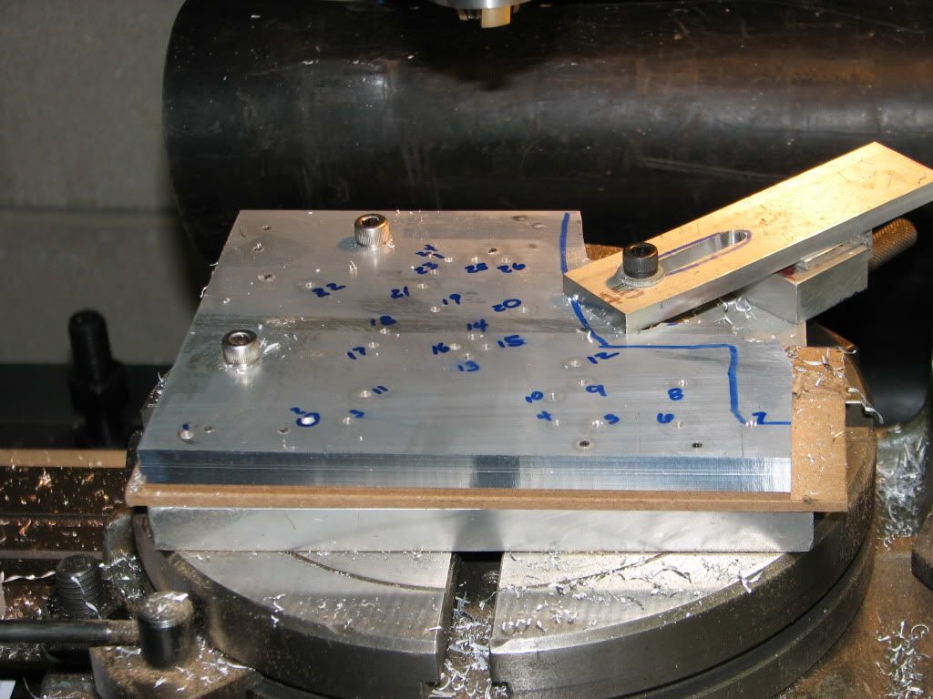
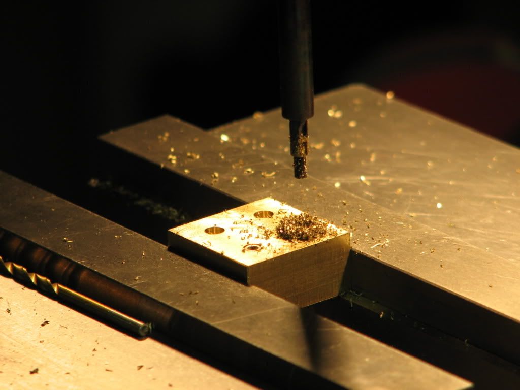
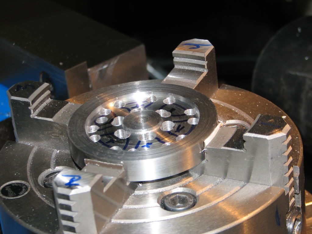
I repeated my steps (no new photos) and this time I used the DRO bolt circle function to drill the holes. The second hole near the hob was "drilled" with center cutting end mill since it overlapped the first hole. The marking on the part is to help me avoid cutting in the wrong place.

flywheel6.jpg


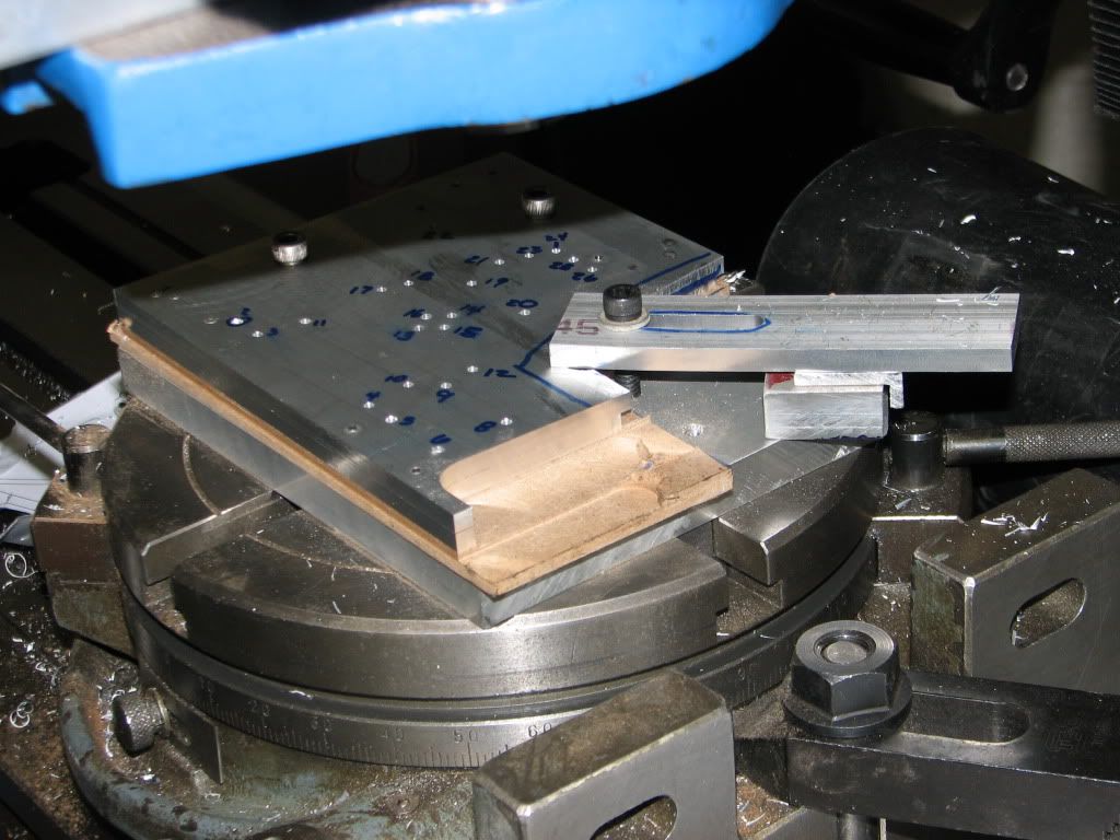
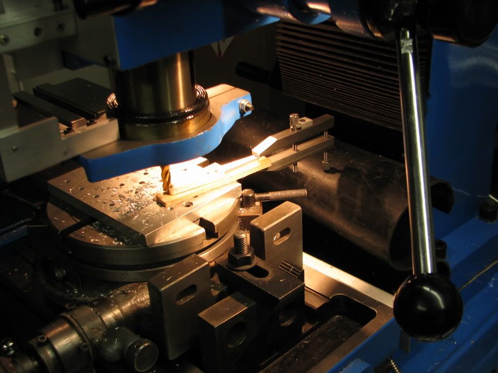
Next I used a 3/16 end mill to rough cut the openings between the spokes. I put a 2 degree taper per side on the spokes for looks.

flywheel7.jpg


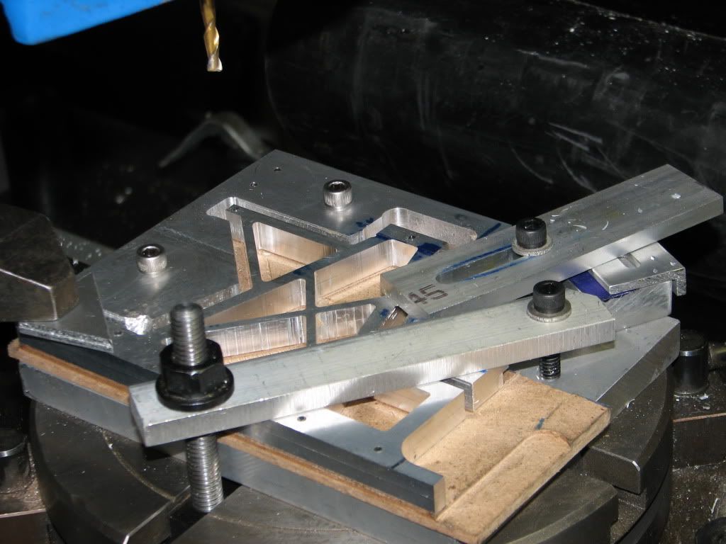
I then went back with a 1/4 end mill to finish the openings to size. The combination of the DRO and the rotary table helped a lot in getting everything uniform and to plan.

flywheel8.jpg


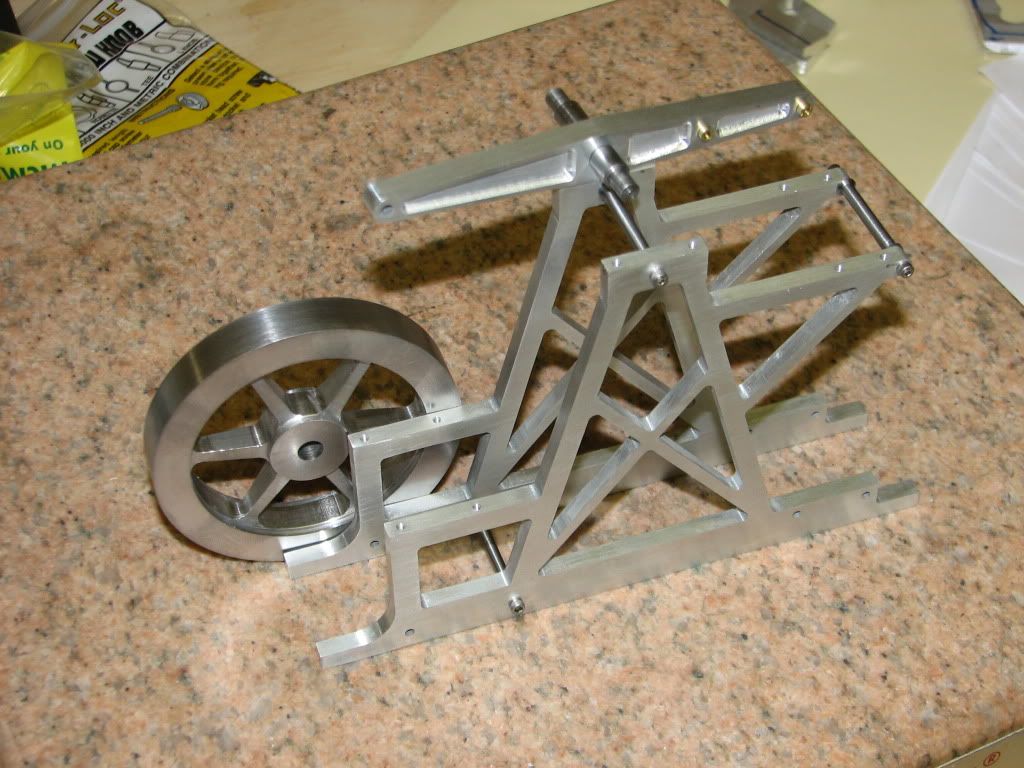
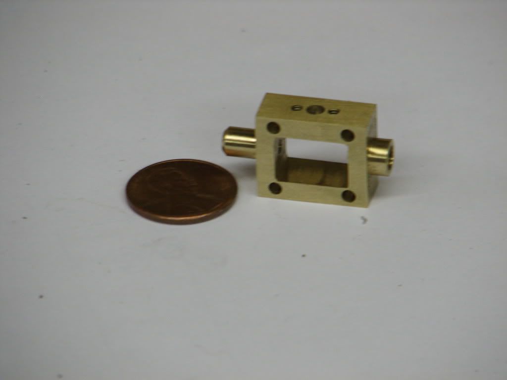
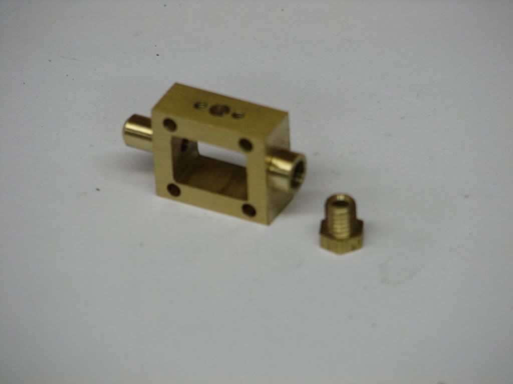
I started the cleanup. Still need to add set screws.

flywheel9.jpg


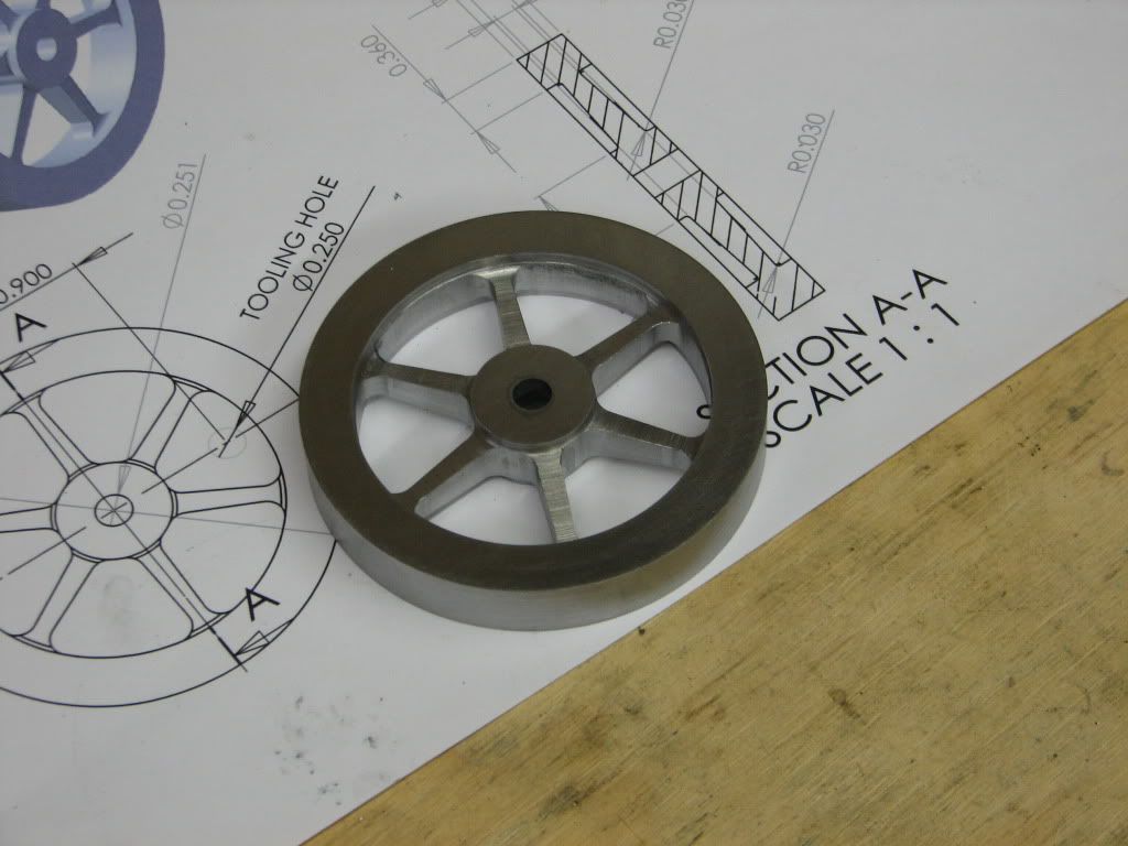
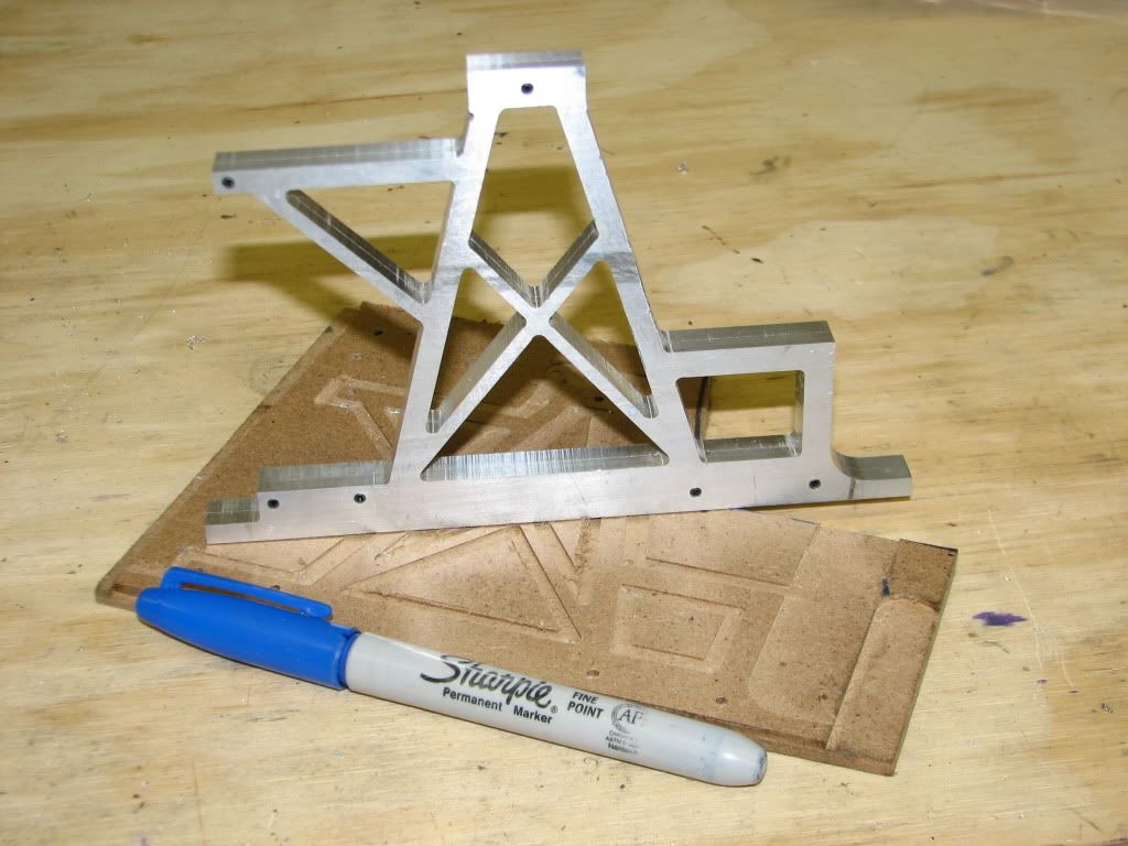
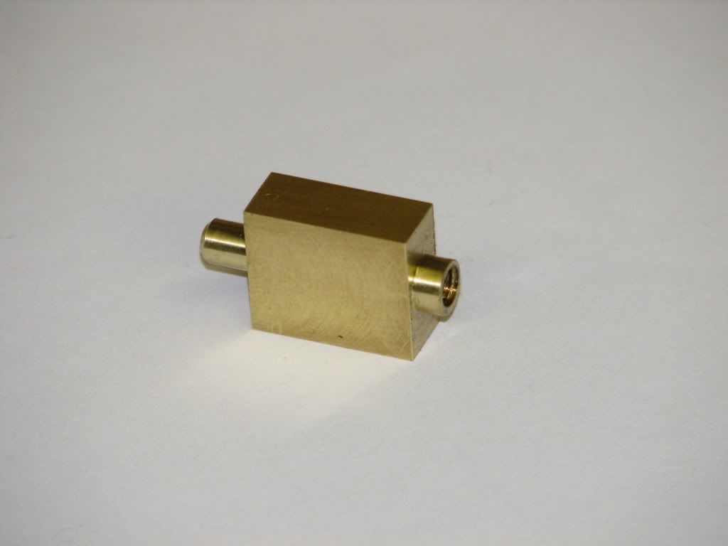
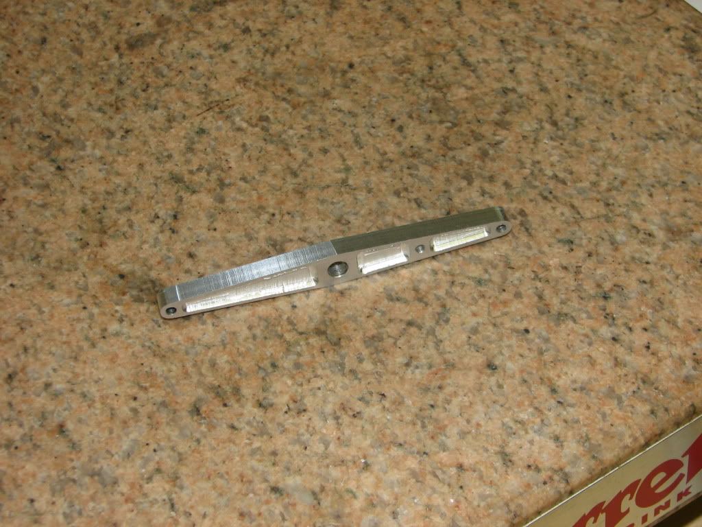
Next up the side frames.

Till next time
Eric
 
That's a great job on the flywheel. Those things are not easy to make, but yours turned out real nice.

Chuck
 
Not easy to make for sure, especially when it's steel. What kind of end mill are you using for steel? I only have the cheapos I get from LMS and they don't seem to hold up to steel very well.

-Trout
 
Chuck -- Thanks for the kind words

Trout -- most of the milling was done with cheap import HSS end mills. I finished the openings between the spokes using an ATRAX solid carbide TiN coated end mill running at about 1600 RPM

Eric
 
Well I have managed to get some more done on my beam engine.

I have been working on the side frames. I started by using a fly cutter to reduce the thickness of a piece of .250 x 5 Ali to about .200 thick (no pictures- sorry). I Then cut the piece into two parts for the two side frames. These got bolted and clamped to a tooling plate on my rotary table. I used a piece of hardboard between the parts and the tooling plate

SideFrame1.jpg


I then drilled holes for the 2-56 screws and pressed in 3/32 spring pins.This will keep the two parts registered for milling and cleanup. Next I milled three sides to have reference edges for locating other features.

SideFrame2.jpg


Using coordinates from a CAD layout of the side frame I drilled a 3/32 hole at the center of each inside radius in the parts. These points will guide the milling operations. Point 2 is circled to remind me that there is a broken drill bit at that location. I had to mill very close to the drill keeping in the waste area and then use a dremel tool and picks to free the drill.

SideFrame3.jpg


I started by milling the large .375 radius at point 7.

SideFrame4.jpg


From there it was a number of hours of playing connect the dots. I took it slowly with a lot of checking to make sure I did not cut where I did not want to. I would cut about .025 on the waste side of the line with several passes to go through the full thickness. I would then make a conventional milling pass to within .010 of the line followed by a clime milling pass to the line. I focused on not making a mistake and did not take any in process photos. I had to move the clamps as the parts were freed from the waste. The results of all the connect the dots ....

SideFrame5.jpg


And here are the side frames as they came off of the mill

SideFrame6.jpg


Next, cleanup of the side frames and then it is time to decide what to do next.

Till next time
Eric
 

Great work on your engine.

Some serious patience, skill and concentration you have displayed, resulting in some beautiful parts.

Well done!
 
Real nice work there Eric.

I fully understand how long things like this can take, and how easily it is to be distracted enough to make a mistake. I have made a few flywheels that needed a redesign half way thru, all because of a lapse of concentration.
I usually warn the household that unless it is to do with life or death, DO NOT DISTURB.

Keep up the good work and showing us what you are up to.

Bogs
 
Very nice Eric. I can appreciate the patience and attention to the process making these frames took. It was worth the effort. Thm:
 
I am back

I never said this would be a fast build but I did not expect it to be more than a month between posts!!!

I have gotten some time in in the shop but have not documented the progress so here goes.

I made a couple of special tools out of drill rod. First a small punch with a small pip on the tip to drive the roll pins out of the frame. I did not want to risk having the punch gouge the side of the hole and I did not have a punch of the proper diameter. Also a pair of filing buttons for rounding tapped 2-56. All were hardened and the punch was tempered.

specialtools.jpg


After quite some time with file and sandpaper I had most of the tool marks out.

framecleanup.jpg


To drill and tap the holes on the edge of the frame I used 1-2-3 blocks to get more support above the mill vise.

IMG_4763.jpg


The next part I attacked was the beam. I started by squaring up a block and drilling the 4 holes. The part went on the rotary table with the jig plate to mill the angles. With 2 pins I was able to easily mill the 4 angles without moving the rotary table.

beammill1.jpg


I then milled the pockets with an 1/16" ball end mill. To round the corners I put one on the end holes over an 1/8" pin and rotated the part by hand. I was concerned that it would be difficult to control the rotation but I had no problems.

beammill2.jpg


Here is the beam as it came off of the mill

beam.jpg


More to follow

Eric

 
And some more progress....

I next made a few simple turning parts (no photos). I could not resist doing a trial assembly with to parts made to date.

partialassy.jpg


I worked next on the connecting rod Most of the in process photos were out of focus. I got one good photo of tapping the end of the rod. I had to improvise since the v-block I got second hand did not have a clamp.

tapconrod.jpg


Here is the finished rod. The 6" scale in the picture belonged to my father. He got it when he worked at the South Bend Lathe Works after WWII.

Conrod.jpg


The last part for now is the valve slider. This is one of the smallest parts I have made. I am happy with how it came out.

valveslider2.jpg


valveslider3.jpg


That is all for now. Thanks for looking

Eric
 
Well I got some time in the shop this week so I worked on the steam chest.

Started by squaring up a block of brass. I made the two smaller dimensions to size and left the third dimension long by about .125" I center drilled both ends to aid in alignment in the 4-jaw chuck. I first turned the packing gland end and drilled the deep .093 hole for the spindle. I wanted to keep this drill as straight as possible so I drilled .030 t0 .040 and then cleaned the chips. After the .093 hole was drilled I drilled and tapped 10-32 for the packing gland. I then flipped the part and turned the other end and faced to length. Here is the part form the lathe.

steamchestfromlathe.jpg


Next over to the mill. I opened the pocked with a 1/4" end mill then finished the pocket to size with an 1/8" end mill.

machinesteamchestcavity.jpg


I do not have a smaller end mill with a long enough length of cut to finish the corners so I had to filed to make the required clearance.
I then drilled and tapped the side port. Here is the finished part.

finshedsteamchest.jpg


Next was a simple part, the packing gland. I made this from 1/4" hex brass rod. I left the hex slightly longer than the print. If I need to shorten it in the future I will drill and tap the end of a rod to hold the part for facing.

steamchestWpackinggland.jpg


The last part for this week was the valve spindle. This part was turned from 3/16" rod using a live center. Even with the live center I took very light cuts since I was concerned with part flex. To turn off the center I made temporary rest to restrain the part. Here is the parting cut to bring the spindle to length.

trimmingvalvespindle.jpg


Even with the temporary rest the part bent slightly. I was able to straighten it with finger pressure. I was able to get to less than .001" TIR. I hope this is good enough! I then used the mill with the 3/16" rod in the vice with about .300" for the square section extending from the side of the jaw. In one setup I milled the top and two sides of the .125" square section and drilled and tapped the 2-26 hole. The rod was rotated 180 degrees and the final side milled. The part was separated from the stock with an 1/8" end mill.

valvespindle.jpg


I finished with a trial assembly of the steam chest parts.

steamchesttrialassy.jpg


That is all for now. I do not think I will get much done this week due to other commitments.

Thanks for looking

Eric

 
Really nice work Eric. I can appreciate the work (physical and mental) that went into making those great looking parts. :bow: Thanks for posting your progress.

Cheers,
Phil
 
Doc, Phil

Thanks for your kind words. I will post my progress when I get some more done.

Eric
 
Really nice work on teh Beam engine Eric, yet another project that's on my list! The list isn't that long actually but it'll still take me years get through it!

Nick
 
Hello Eric

Very nice work - keep the photos comming - I love it
 
Hi Eric,

Great work you are doing there, I admire your patience and accuracy :bow:

I will be following along.

Regards Jeroen
 
Nick, Mogens, Jeroen

Thank you for your comments and interest. I will continue to post updates as the work proceeds.

Eric
 
I got some shop time this week and managed to make one good part. I started the lower head by squaring and milling the block to size. I then drilled and c-bored for the 4 2-56 cap screws. I used a home made tool I made from instructions on Dean's web site. Thanks Dean. In the picture I have one screw inserted to check the c-bore depth.

LowerHead1.jpg


I next drilled and tapped the 4 2-56 holes on the sides. I also center drilled the top to aid in alignment on the lathe. I mounted the part in the 4-jaw chuck using parallels to get it spaced form the chuck body. I used small pieces of aluminum flashing to keep from marring the part. There was limited engagement in the chuck jaws so I took light cuts. For the 3/8" counter bore I used a center cutting end mill in the tail stock chuck.

LowerHed2.jpg


A little clean up left a good part

LowerHead3.jpg


Today I started the cylinder. I got the piece squared and milled to size and milled the valve ports rather than the drilling in the prints. Next I started to drill and tap the 2-56 holes to mount the steam chest. It was then that I realized that I was working on the wrong side of the part :mad: Another mental slip. I will have to start this part over (but not today).

Here is shiny piece that I may be able to use for another part in the future.

Mistake.jpg


I have been putting off working on the crank shaft because I can not decide how I want to make it. Should I make a one piece crank as I did on my first engine or should I go with the built up design in the plans? I have not done any silver soldering so I would need to get the solder and flux and do some test parts. If I go with the built up fabrication, how much clearance should I allow between the drill rods and the crank webs for the solder? Would it be OK to go with a sliding fit and put counter sinks on the webs for the solder? Any suggestions would be greatly appreciated.

Thanks for looking

Eric
 
Back
Top