An Upshur Farm Engine (first I.C.)

Home Model Engine Machinist Forum

Help Support Home Model Engine Machinist Forum:

This site may earn a commission from merchant affiliate links, including eBay, Amazon, and others.

tvoght

Well-Known Member
Joined
May 7, 2012
Messages
80
Reaction score
1
With a couple of steam engines under my belt, I've been wanting to build an
internal combustion type. I did some research and read some build logs here,
and it finally came down to Jerry Howell's Farm Boy or one of the Upshur farm
engines. After obtaining the plans, I really liked the Farm Boy, and I even
built a rocker arm and rocker arm post for it before the Upshur plans arrived.
After studying these, I decided to do a horizontal water-cooled Upshur farm
engine instead, as it seemed simpler to build.

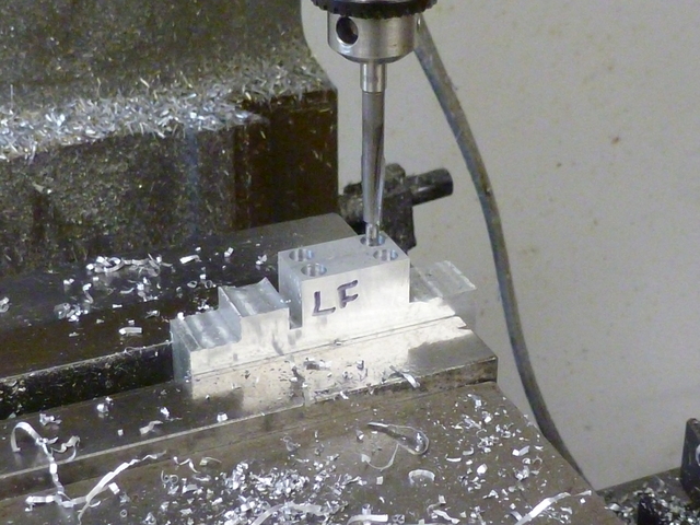
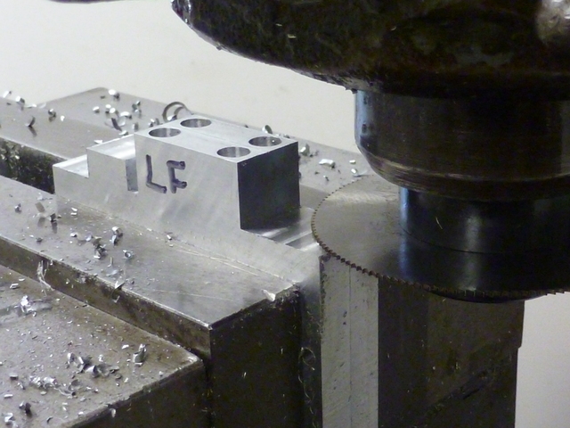
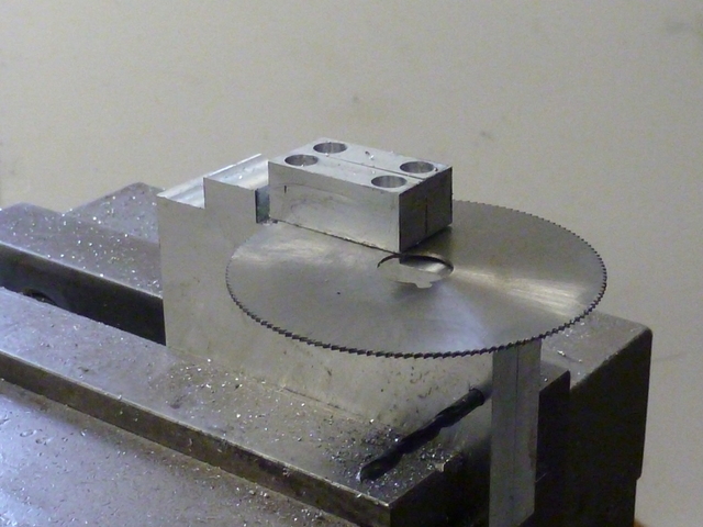
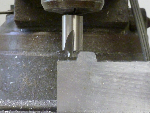
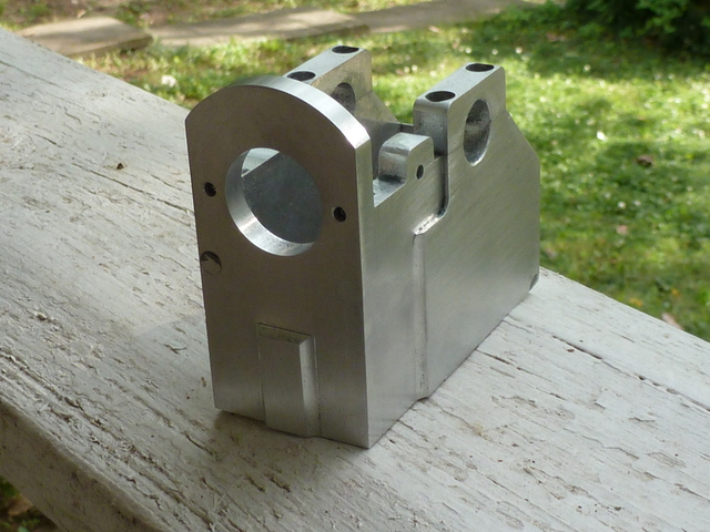
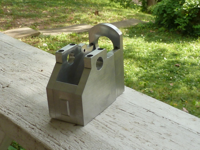
I'm starting this log after having completed enough to have the confidence to
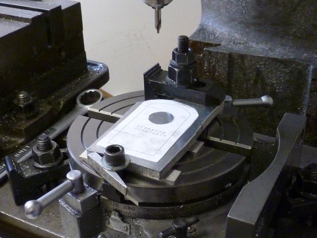
continue, so I'll be starting with a short burst of accumulated photos.
I make no claims to having photography skills, and if a photo is poorly
focused, I included it because I thought it essential to the story.

I welcome any and all criticism. I'm here to learn.

 
While sticking to the plans for all critical dimensions, I'm taking
some license with the appearance of the frame and cylinder. The plans call
for the frame to be built of 1/4 aluminum plate, but I have some cast aluminum
tooling plate on hand that I want to use. It's 5/16 thick, and I'm going to
use the extra thickness in places to add decorative touches in relief.
In the following photo, I've rough sawn a couple of side frame pieces
and clamped them on top of each other on a sacrificial tooling plate of the
same material. The sacrificial piece was a little small, and the lower right
corner of the work pieces extended over, thus the weird clamping of a little
corner piece for support.
5.jpg


Here, I've side-milled the bottom and right sides, cutting a little into
the tooling plate. Referencing from the machined sides, I drilled two screw
holes where the back plate will attach to the sides. The side-milled
surfaces looks a little rough... By the way, whereas the plans have the
frame fastened by cap screws clearly showing all around, I intend to hide
all the screws in counterbores and then plug the counterbores to give the
appearance of a one-piece cast frame (to be painted).

10.jpg


The clamps were then switched opposite to mill the other two sides.

15.jpg

 
I clamped the milled-to-size side plates side-by side in the vise to
shape their top edges. Since the frame is to be one piece when finished,
the crankshaft can't be installed by removing one of the sides, as in the
original design (which has the bushing holes bored directly into the
sides). This one will have bushing caps to be removed for crankshaft
access. Ahead of the bushing caps is a protrusion where the cam gear axle
will mount. This is all a little fancier than the original, in which the
side plates had flat, featureless top edges.

20.jpg


I drilled and counterbored for the bushing cap screws (with markings so I
can hopefully put the caps back where they came from after I separate
them). I drilled first for 6-32 tapping deep enough to go well past
the caps and into the sides, then enlarged for 6-32 clearance just past
the depth of the caps. Note that I accidentally cut too deep when I
milled the top of the cam axle mount to height. As luck would have it,
that feature is only needed on the left side, so the boo-boo will be
milled off of that other plate.

25.jpg


Here I'm preparing to saw off the bushing caps. There were unanticipated
clearance issues here, but I finally worked it out, still knowing I would
not make it all the way left without getting into the cam axle mount.
I went as far as I could on one side, then on the other, stopping just short
of hitting the other feature.

30.jpg


The plan was to finish the cut with the saw blade held between my fingers.
Slowly and awkwardly back and forth. It worked, and the operation wasn't as
onerous as I thought it might be.

35.jpg


With the bushing caps removed, the area where they had been was milled
level, and the cam mounting feature was rounded over. Yikes, I have a bit to
learn about locating the rounding-over bit. A bit of filing is in order...

40.jpg


The bushing caps were cinched side-by-side on a parallel in the vise, and the
mating surface with the sides milled flat. The caps were then flipped, and
the top corners rounded. Better this time. Maybe I'm getting the hang of it.

45.jpg

 
Back to the tooling plate, where it took some effort to get the plates
aligned with each other and square to the mill. I had previously drilled
the screw holes well into the tooling plate so that I could use drill bits
as alignment aids when clamping the sides back down. This helped some,
but was still too sloppy for good alignment. For final alignment, I used
some short parallels along the edges and aligned with the mill cut in the
tooling plate. Had I known that's how it would work, I'd have cut deeper
into the tooling plate to give a good solid edge to align the parallel
with (I've got a nifty set of small 3" long parallels which performed
admirably here). I've experimented with a variety of edge-finding
apparatus, and now I'm using a collet-mounted hardened rod with
cigarette papers or feeler gages to touch off the part. It's working
for me. You see the rod here. The top and right edges were found, and
the DRO zeroed for the center of the crankshaft bore.

50.jpg


Once clamped down, and with the top edge located, I re-attached the bushing
caps (did we miss the part where I tapped the side plates 6-32 for
the caps?). I then center drilled, drilled and reamed the crankshaft
bushing bores (drilling well into the sacrificial plate). I then counter-bored
the screw holes on both side plates.

55.jpg


Back in the vise, and using a bushing to aid alignment, I prepare to
angle off the back at a 45 degree angle.

100.jpg
 
I cut out the frame front on the rotary table. No tooling plate was used,
since the stock is 5/16" and the finished plate will be 1/4" thick. I'll cut
a little deeper than a quarter inch and then flip the plate and cut to
thickness to release the part. It's a little more complicated than that,
because I'm going to leave a full-thickness decorative feature on the front
of the plate. You'll see further down. A little paper template is used
to help me in aligning the clamps without interference.

65.jpg


I drilled and reamed a 3/8 hole at the cylinder center location and four
screw holes where the sides attach. I intend to use these holes to help
with alignment when I flip it for adding the decorative feature.
We'll see I have a little trouble with that.

70.jpg


Here, the sides and bottom have been milled to a depth of .29.

75.jpg


The top arc has been cut to the same depth, and the cylinder hole opened up,
though still not to size, I intend to bore the cylinder hole and face the
front in one operation when the frame is together as one one piece, and there
is a dummy crankshaft rod installed for square alignment.

80.jpg


The plate is flipped and I use my handy-dandy locator rod to center it up
and give me the center of the rotary table as a reference. The plan was to
use the four screw-holes as aids to align to the axes, but that attempt
failed because I forgot to lock down the rotary table! We'll see further down
how that resulted in my decorative feature being somewhat misaligned.

85.jpg


Here you can see where I've outlined the rectangular feature with a ball-end
mill and then milled everywhere else to a depth of .0625 to release the part
and reduce it to a depth of .25. I'm just about to cut it free here.
Notice that the upper half or so is .031 thicker. Again, the plan is to
face that off and bore the cylinder hole in a later step when the frame is
assembled. Some other features will be added at that time, too.

90.jpg


There it is. The misalignment of the relieved decoration is not real obvious
in this shot, but it is visibly out when viewed straight on. I'll clamp it
down later and square it up with the ball-end mill.

95.jpg
 
The frame's back plate is made a lot like the front plate. I clamped a piece
of stock to the mill table and Milled the outline .270 deep.

105.jpg


I flipped the part and aligned the machined edge to the mill slot by sticking
5/8" dowel pins in the slot and holding a parallel against the pins. I then had
a reference to press the workpiece against for clamping down. I've lined
things up like this so I can squarely put another decorative feature on this part.

110.jpg


I milled the decorative feature .0625 deep with a ball end mill, and then
the surrounding area with an end mill to the same depth, ending with the
outer edge to separate the part.

115.jpg


Here is the freshly separated part, and you can see remaining material where
the part separated. That will have to be filed away. Worse, It seems I went
a thou or two deeper with the ball-end, meaning a good deal of cleanup to
get rid of that groove. Live and learn.

120.jpg


Here it is after a lot of cleanup with file and emery.

125.jpg


I drilled and tapped holes along the edge where the side plates attach, and
then on an angle block in the vise, milled the 45 degree angle that will
match the angle at the back of the frame sides.

130.jpg


I just had to fit the completed parts together for a look-see.

135.jpg

140.jpg
 
Great looking start Tim. Thanks for sharing your build. I'm looking forward to following along.

Regards,
Rudy
 
Tim

I will be following your progress and learning on the way. Great photos. Much better than mine.

Vince
 
Brock, John, Rudy, Vince: thanks for your comments.

Rudy, I have seen your Upshur hereabouts, and I just hope mine will be as nice by some fraction.

Tim
 
Very nice write up and photos! Thanks for sharing.
 
Great! I'll be following along with interest - thanks for sharing :bow:
 
I always like it when folks add their own panache to a design. It'll be a looker, I'm sure.

-trout
 
Thanks everybody for looking!

I got a little more done tonight.

The front plate with the crooked decorative relief on it was clamped down
on the mill table (straight this time) and the feature trued up with a
ball-end mill. I now have the 4 plates of the frame as I want them at
this stage. As I said, the idea is to make this frame appear as one
monolithic piece instead of 4 plates screwed together. I cleaned
everything up in soap and water, let it dry out, and then stuck it together
with 609 loctite. With everything lined up just so, I tightened the screws
down hard.

I turned down a quarter inch aluminum rod in the lathe to the size of the
counter-bores for the screws. Then I cut off eight little plugs (manually,
with a hacksaw), facing off after each cut.

I mixed up a small batch of JB Weld, and smeared a glob on the smooth end
of each plug, then plugged each counter-bore with one. The hack-sawed ends are
protruding (as you see in this photo), and I intend to file or mill them
flush later on. When the frame is painted, I hope there is no trace of
these. Think it'll work?

145.jpg
 
The one-piece frame was clamped down true, and areas of the left side were
reduced to 1/4" thick so that the cam and pushrod will have the proper
dimensional relationship to the cylinder. The forward area of the sides was
reduced to meet up properly with the front plate.

150.jpg


Clamped on the other side, again the forward area was reduced to meet the
front plate.

155.jpg


I put a .500 ground rod through the reamed crankshaft bushing holes and
clamped up straight against the side of a large v-block. I indicated the rod
to be sure it was parallel to the mill in the y and z axes, Then I cleaned
up the front plate with an end mill.

160.jpg


In this setup, I bored to size the hole where the cylinder sleeve will seat.
The two cylinder mounting stud holes were also drilled and tapped
(not shown in this shot).

165.jpg


I like the appearance of depth I got here. It's got some character.
I'm pretty happy with the way the plugs in the screw counter-bores worked out.
They're mostly invisible, except one in front that was mostly milled away.
On that one though, the JB Weld that preceded the plug into the hole fills the
void and there is a smooth surface, it's just a different color.

170.jpg

175.jpg
 
Looking good Tim. It is indeed looking like it's all one piece. Very nice.

Rudy
 
Thanks Rudy. Thanks to all who are watching. I got some time in the shop tonight, but won't be able to write up a report til tomorrow night.

--Tim
 
Very nice. You might consider making the crankshaft extend a little longer past the frame (left and right sides) than what the plans call for since you are a little thicker on the frame. As you've noted, the sleeve for the smaller gear will be affected but you may also run out of crankshaft as you add the weight assembly on the left and whatever ignition assembly you decide to use on the right side. Always easy to shorten the crankshaft after, but hard to lengthen.

-Trout
 
Back
Top