Adding manual clutch to model engine

Home Model Engine Machinist Forum

Help Support Home Model Engine Machinist Forum:

This site may earn a commission from merchant affiliate links, including eBay, Amazon, and others.

Brian Rupnow

Design Engineer
Project of the Month Winner
Joined
May 23, 2008
Messages
14,969
Reaction score
8,250
Location
Barrie, Ontario, Canada
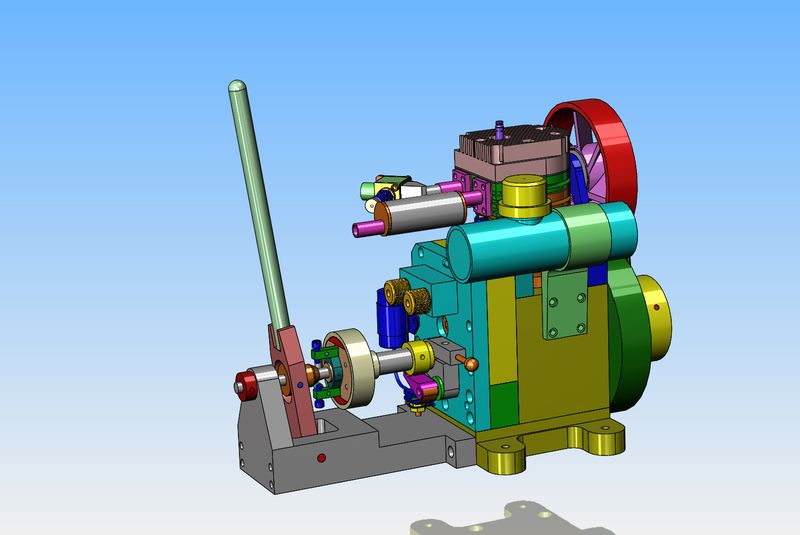
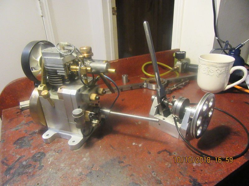
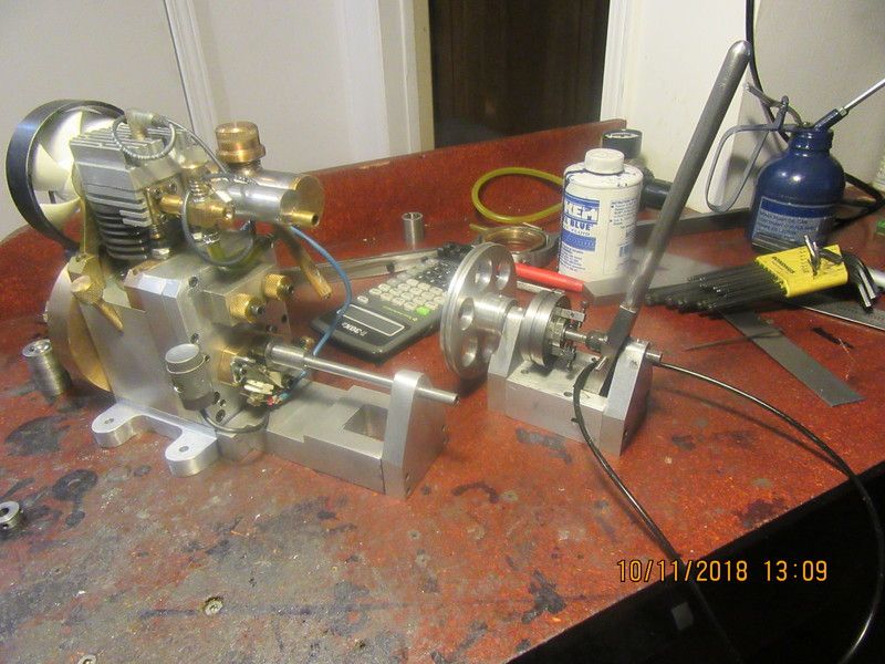
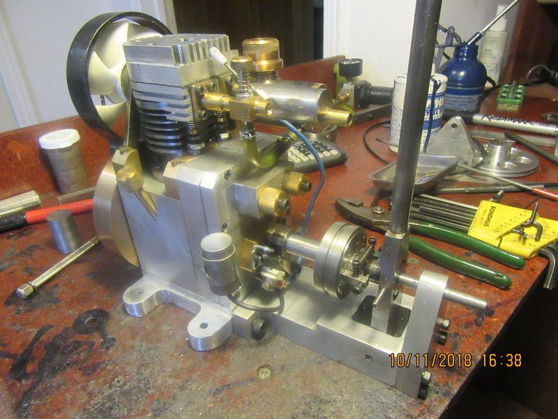
A few years ago I had my single cylinder flathead i.c. engine featured in Home Shop Machinist magazine. It was built by a number of people, and since then has mostly set on a shelf in my office collecting dust. I have been messing around with various styles of manual clutch this last month or so, and have decided to install a manual clutch on the flathead engine. I designed a "line shaft clutch" last year, and in it's final guise as an expanding shoe clutch it worked so well that it has become my favourite style of clutch. I am going to modify the clutch and make it a direct drive from the crankshaft of the engine.
6W8DFV.jpg
 
Hot diggity dog--I made a part today. In fact, I liked it so much that I made it twice. That long extension hanging out of the engine started life as a piece of 1/2" cold rolled, turned to .25" diameter over most of it's length with a 3/8" counterbore in the 1/2" end to slip over the engine crankshaft. Somehow, I managed to read my micrometer wrong and turned the first one to 0.22" diameter. Ah Poop!!! So, into the box of miscellaneous short ends it went, and then got remade. In the picture, you see all the victims. The flathead engine, the line-shaft expanding shoe clutch, and the single part that was successfully made.
kU3qP1.jpg
 
Hello Brian

I have a project that I would love to put a clutch on and this would be just what the project needs, are you or have you posted drawings for your clutch?

Mike
 
Mfrick--I sell a complete set of technical drawings for this clutch. There is one assembly drawing, 9 part detail drawings, and a bill of materials. send $25 Canadian funds to my paypal account under [email protected] and when they notify me the money is there I will send you all the drawings as .pdf files.
Brian
 
Hello Brian

Thanks for the quick reply

I have just sent you the funds you should get by 10/12 my email address is [email protected]

Thanks I plan to build the clutch and attach to my Bruce Macbeth engine and drive an air compressor with it.
I look forward to getting the drawings.

Mike
 
Mike--before I get too crazy and send you the wrong drawings, let me tell you what is happening. I designed the line shaft clutch a year or two ago. I now am in process of using the parts from that clutch to make it into a clutch which attaches to my engine. In the pictures you can see the original version of the stand alone clutch, which I haven't dismantled yet, and you can also see the new shaft, base, and endplate (arranged beside my engine) onto which the parts from that original clutch are going to be used on. So--Do you want the drawings of the original stand alone clutch, or the updated drawings of the clutch with the modified base, endplate and shaft.--It will be easier for me if I give you drawings of the most up to date one which attaches to my engine.--Brian Rupnow
GTU9qm.jpg
 
So here we are at about 85 percent--Everything goes round and round with no binding and no clearance problems. I have to trim the clutch shaft to length and drill a hole thru the shaft for a dowel which locks the expanding shoe carrier to the shaft. Also have to drill and tap two places at the sleeve end of the shaft to lock it to the crankshaft. Next step is to clean up the drawings tonight and send them off to someone.
pssDjq.jpg
 
So, today we have a video of the clutch in operation. I would call this clutch about 85% effective. The fact that the clutch drum rotates freely on the driven shaft and only revolves under power when the clutch is engaged means that the clutch wants to "creep" a little even when it is fully disengaged. Of course the trick is to find something to drive which has enough resistance to keep the clutch from "creeping" but not so much resistance that it stalls the engine when the clutch is fully engaged. I already have an idea in the back of my head on how to build a "non creep" clutch, and will probably post about it when time allows. The people who bought plans for this clutch will get new free plans for the new "non creep" version after I have built and tested it. The last 20 seconds shows me de-mounting the camera and tripod--I thought the camera was turned off.
 
Last edited:
As you seen in the previous video, the clutch performed quite well, but had a tendency to want to "creep" even though the clutch was fully disengaged. This was caused by friction between the rotating clutch shaft and the clutch drum which was supported by it. I have a new design using almost all of the current parts, but arranged a bit differently so that the clutch drum will never see any frictional influence from the rotating clutch shaft.
uqMxB8.jpg
 
This shows what the previous clutch (this morning) looked like in cross section. The fact that the clutch drum was supported by the rotating shaft made it want to "creep" even when not engaged.
ScIlHf.jpg
 
Today I have spent the entire day reconfiguring the clutch so the drum would not "creep" due to the friction from the rotating shaft which it was riding on. Not a lot of changes to the clutch itself, but had to change the bracket a bit by lengthening the hole that the clutch arm sets in and shortening the shaft. Everything is back together now, and the clutch is performing well, except now the drum wants to creep because of the near proximity of the shoes inside the clutch drum. However, this will get sorted out this week. I have a bit of "real work" starting tomorrow, so will fit my model work in between things.---Brian
 
I have my detective/analyst hat on now, and think I have found a clue. The clutch is disengaged in the picture. You can see the hot pink return spring that returns the clutch shoes to their home position when the tapered cone is not forcing them apart to engage the clutch. The green arms which hold the two cap-screws the spring is attached to and the other two dark blue screws that are forced apart by the tapered cone when the clutch is engaged are heavy little devils, and I'm sure that when the engine is turning at around a thousand rpm, they are acting as counterweights. Centrifugal force is making them fly out enough to make the shoes rub on the inside of the clutch drum. When I shut the engine off, the drum spins freely and I don't feel any drag. A stronger spring should fix that, but I've worked enough today. I will get to that later this week.---Brian
8gX3Ia.jpg
 
Last edited:
I am busy right now with a drop in design order for a welding fixture for a General Motors supplier. As soon as I get the chance I am going to put another spring on the opposite side to the current one and see if that cleans up the problem of "shoe drag".
 
Today we have success. Adding a second spring to the clutch shoe return mechanism was enough to overcome any centrifugal forces, and solved the problem of "clutch creep". I'm happy with this clutch now and do not plan any farther work on it.--Brian Rupnow
 
Brian
I think we all have learned alot about clutching because your desire to have something that worked and works well. Your series of different styles was very informative. I have enjoyed it very much and feel I could build any of them.
Thank you so much for sharing.
Nelson
 

Latest posts

Back
Top