A V8 Maybe

Home Model Engine Machinist Forum

Help Support Home Model Engine Machinist Forum:

This site may earn a commission from merchant affiliate links, including eBay, Amazon, and others.
Hi Baz
Did you use the Sheet specs for the Cam Mate ?
Im tossing up building a Cam grinder and grinding all my future ones.
Pete


G'day Pete,

I used this cam calculator for the indexing.
basically input the data from the spec sheet in the plans.

http://modelenginenews.org/design/CamTable.html

I then used my cnc mill and rotary indexer for the cuts, finished with blending with a file and emery cloth.

The crank was done by the same process you posted.
 
Last edited:
Pete
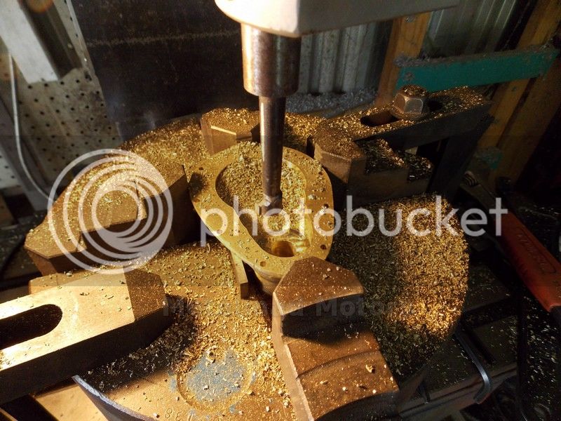
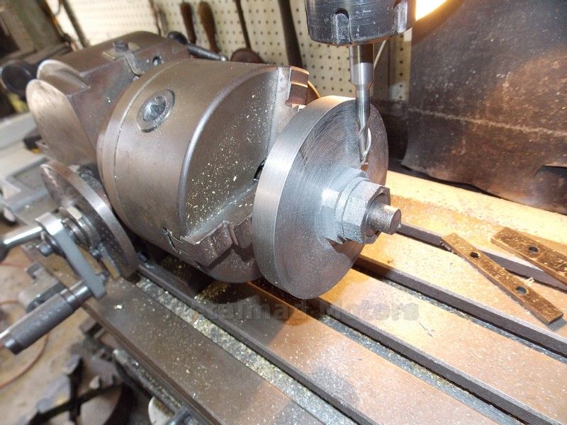
come on, the second one is a trick picture dont trell me you were using 2 way face take to hold your
timing cover to your mill tableRof}Rof}
No Tricks Luc scratch.gif
I clamped one end and did the holes one end , then clamped the other end, took off the first clamp and did the holes on the other end.
I took off the second Clamp so you could see my lovely casting :big:
Pete
 
hogging out the gear cover, good to see how nice the casting is :cool:
Pete
 
hey Pete
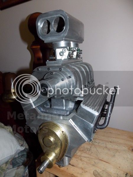
everytime I look at your molding product I'm flored.:eek:
How long have you been doing this

cheers
 
Hi Luc
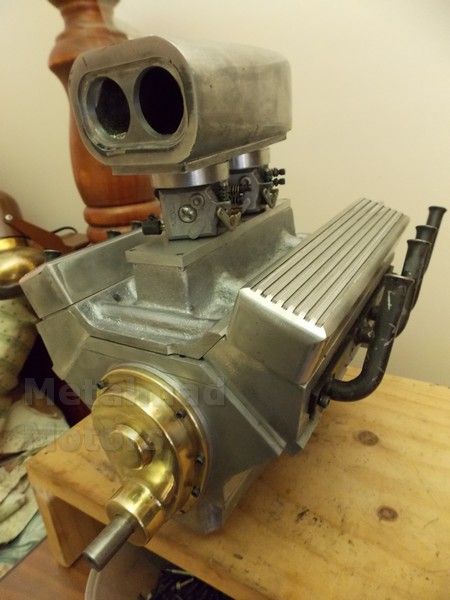
This is my first Casting project buddy and the main point of the build is simply to learn a few basic casting tricks so that I will be able to cast up my own Engines in the future.
I have no plans to try cast iron but have proved to myself I can do simple patterns in both alli and Brass.
Pete
 
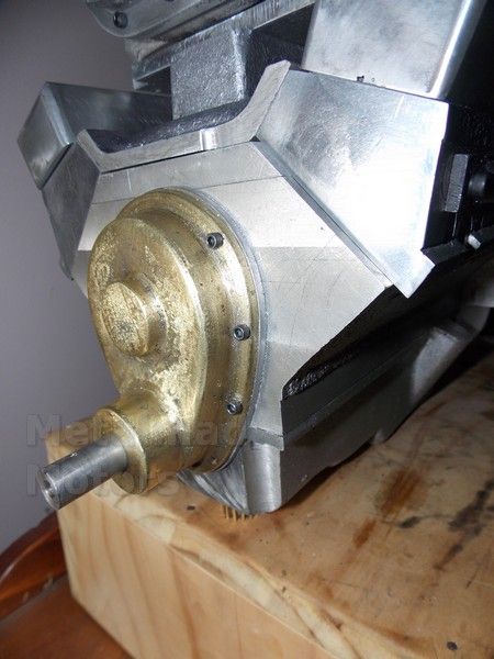
Ive drilled and tapped all the holes for the cover now except the bottom two which I will do later with a sump gasket installed.
Pete
 
Hello there Pete, it sure is looking good. Will keep following your build and hope to hear it run.

Take care and happy machining
 
Hi Danny
Give me 6 months and I think she will be close ;D
There is still a whole lot to do, including a Cam grinding machine to build before then.
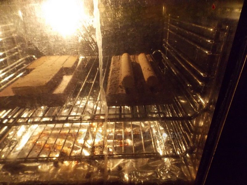
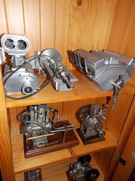
Hay Baz I made up some cores for a redisigned Blower today but did not use flour.
Last time I had problems with the core raising and spliting like a cake but this time I added the treacle to the water and mixed that with the sand and then cooked at 250 degrees C untill brown.
Much better;D
Pete
 
Hay Baz I made up some cores for a redesigned Blower today but did not use flour.
Last time I had problems with the core raising and splitting like a cake but this time I added the treacle to the water and mixed that with the sand and then cooked at 250 degrees C until brown.
Much better;D
Pete

G'day Pete,

I Reckon the cores would have smelt good, did ya whack on a batch of scones as well:D
I still have to get around to casting with cores, as soon as my mill is up and running again I will be going hammer and thongs at it, will have a go then.

Went to the old boys place today, here is a couple of pics of one of the cams I made for the same engine you are building.


I cheated, all done by cnc, did use the indexing chart generated by the cam calculator though, 1 degree increments then finish by hand.

Baz.
 
Last edited:
Hi Baz:

Just for interest sake, what numbers did you enter into CamCalc (I assume that's what you used as your cam calculator).
Cam looks good.

Sage
 
Hi Sage,

The figures i used are as follows,

Base circle radius, 0.375"
Valve lift, 0.105"
Cam action angle, 156 degrees
Flank radius, 0.93"
Table row increment, 1 degree
Engine speed, 6500 rpm

Pete where are you, we are missing your progress.

Cheers,
Baz
 
Last edited:
Hi Baz
Im not far away Mate but I slow down to a crawl when it gets cold at night!
Cam looks great Buddy, Its one thing Im not looking forward to :hDe:
Pete
 
G'day Pete,

Yeah I hear ya,

Getting pretty cold here in Perth at night now.

I go back to work in the morning, had 1 month off coz the missus and I had a new addition to the family (band new baby girl 1 week ago)
36 years old with a newborn ??? :eek: :eek: :hDe: ;D Thats the process I went through.
Back to the Pilbara for 8 days, we get mid 30's in winter there.

The cam is not to bad to make, very time consuming but is a buzz to look at when finished.
Steve Huck has a great tutorial for the whole process, (Onya Steve, love your work)

Here is the link for the tutorial.

http://www.mikes-models.com/camarticle.html

Cheers,
Baz.
 
Hi Sage,

The figures i used are as follows,

Base circle radius, 0.375"
Valve lift, 0.105"
Cam action angle, 156 degrees
Flank radius, 0.93"
Table row increment, 1 degree
Engine speed, 6500 rpm

Pete where are you, we are missing your progress.

Cheers,
Baz


Hi Baz:

Not sure what you have for the other cam (exhaust or intake) or for the lobe center angle but the engine's going to sound pretty good with that cam. The ever famous Duntov 30-30 cam which is very lumpy only has approx 290deg crank duration and you're pushing 312deg. How much overlap or what lobe center angle and other specs have you planned on?


Sage
 
Hi Baz
Congratulations on the little one :)
I notice you have redesigned the Cam with much wider cam lobes and no center bearing, did you use the 110 degree lobe separation?
I must admit to not even looking at the sheet until your post, Its just too scary :eek:
Today I decided to put some flats on the flywheel as Ive found I have trouble undoing the collet nut holding the flywheel by hand.
The other day I changed the "B series" belt on my lathe and noticed the finish is not as good when I took a cut of the front of the flywheel.
I'm wondering if the belt is on the tight side and will loosen it off before using it again or maybe ive just done a tip.
I have also done a lot of work on the gear cover but have been plagued with a couple of minor flaws so it looks like I need to get out the files again.
I'm really over this gear cover I tell you!!
Pete

 
Hi Guys
I hit a problem with working out my firing order to cut my cam, and finally found I had installed the Crank backwards :noidea:
I was able to press off the second bearing at the rear but will have to redo my front keyways :shrug:
My firing order will be 18724365 as I just can not see how the sheet specs would work at all.
I turned my blank to a snug fit in the block for the center bearings and will start preparing the blank this week, the outer bearings will be bronze.
Steve Hucks formula for the turning offset is.
flank angle-(base circle/2)
.696-(.375/2)
.696(.1875)
.5085 turning off set
I used the little Demon flank angle as I really can not make heads nor tails of what the sheet says.
Now a question for the guys!
I looked up some cam specs on the net and if I cut my lobe flanks like this with 110 between lobes centers will it be OK???????????????
IVO-9 degrees BTDC
IVC-41 degress ABDC
EVO-47 degrees BBDC
EVC-3 degrees ATDC
(IVO is inlet valve open)
(EVO is exhaust valve open)
I cut the high tensile blank to a snug fit in the block today and will continue this week.
Am a little worried about a interupted cut in such a hard material but will see how I go.
Pete
 
Hi Pete,
Whenever someone builds an I.C. engine they make a cam to the specs that are published or when scratch building to what they think will work. When they get the engine running they, including myself, are so thrilled with the engine that they stop there. By that I'm saying I don't know of anyone who says, "gee, the engine runs good but I wonder how it would run if I made another cam to somewhat different specs." And so forth and so on if you get my drift. It takes a lot of time and concentration to make a cam and I don't know anyone that wants to make 2 or 3 or 4 of the things. If a person gets his engine running and it has some problems, starting, idle, throttling etc, does he ever say, "well maybe it's my camshaft." I never have!
Cam numbers are just that, numbers, without accompanying numbers for compression ratio, operating rpm, head flow etc that's all they are. In the full sized world of cams all these specs need to be used to determine the best cam for the job.
I have always machined symmetrical cams, not for any particular reason but just because.
Another set of factors that need to be considered are what type of cam you're going to use, for flat tappets or roller lifters. This will determine the the tangent points of the cam shape. As with all cam numbers there is no magic number for lobe separation angles. The number 110 is thrown around but here again this is determined by other factors.
The bottom line is I wouldn't be too concerned with what the cam is or isn't going to do, just make something reasonable and the engine will work.
 
Hi Guys
I hit a problem with working out my firing order to cut my cam, and finally found I had installed the Crank backwards :noidea:
I was able to press off the second bearing at the rear but will have to redo my front keyways :shrug:
My firing order will be 18724365 as I just can not see how the sheet specs would work at all.
I turned my blank to a snug fit in the block for the center bearings and will start preparing the blank this week, the outer bearings will be bronze.
Steve Hucks formula for the turning offset is.
flank angle-(base circle/2)
.696-(.375/2)
.696(.1875)
.5085 turning off set
I used the little Demon flank angle as I really can not make heads nor tails of what the sheet says.
Now a question for the guys!
I looked up some cam specs on the net and if I cut my lobe flanks like this with 110 between lobes centers will it be OK???????????????
IVO-9 degrees BTDC
IVC-41 degress ABDC
EVO-47 degrees BBDC
EVC-3 degrees ABDC
(IVO is inlet valve open)
(EVO is exhaust valve open)
I cut the high tensile blank to a snug fit in the block today and will continue this week.
Am a little worried about a interupted cut in such a hard material but will see how I go.
Pete

Hi Pete, you wrote that your cam timing is 18724365, GM LS v8 engines are 18726543 is this maybe the reason for the confusion? also how are you numbering the cylinders? standard gm 1357 on the right 2468 on the left looking at the front? Great build by the way, I like the castings
John
 
Hi Pete, you wrote that your cam timing is 18724365, GM LS v8 engines are 18726543 is this maybe the reason for the confusion? also how are you numbering the cylinders? standard gm 1357 on the right 2468 on the left looking at the front? Great build by the way, I like the castings
John


The numbering is wierd. Pete has made many references to the drawings being strange. There are 2 different firing orders in the drawings. The one shown by pete and on the cam sheet the standard Chevy order. Also on a chevy, the driver/left side is the cylinder closest too the front of the engine and numbered one. On this model the front cylinder is on the right is forward but still numbered #2. It is weird but not a big problem it you keep your head in the game.
 
The numbering is wierd. Pete has made many references to the drawings being strange. There are 2 different firing orders in the drawings. The one shown by pete and on the cam sheet the standard Chevy order. Also on a chevy, the driver/left side is the cylinder closest too the front of the engine and numbered one. On this model the front cylinder is on the right is forward but still numbered #2. It is weird but not a big problem it you keep your head in the game.

Yes you sure are right Steve, can get confusing for sure. On another note when are you going to make the rotors for the blower? that's an awesome build

John
 

Latest posts

Back
Top