A Smaller Steam Engine For A Smaller Boat

Home Model Engine Machinist Forum

Help Support Home Model Engine Machinist Forum:

This site may earn a commission from merchant affiliate links, including eBay, Amazon, and others.
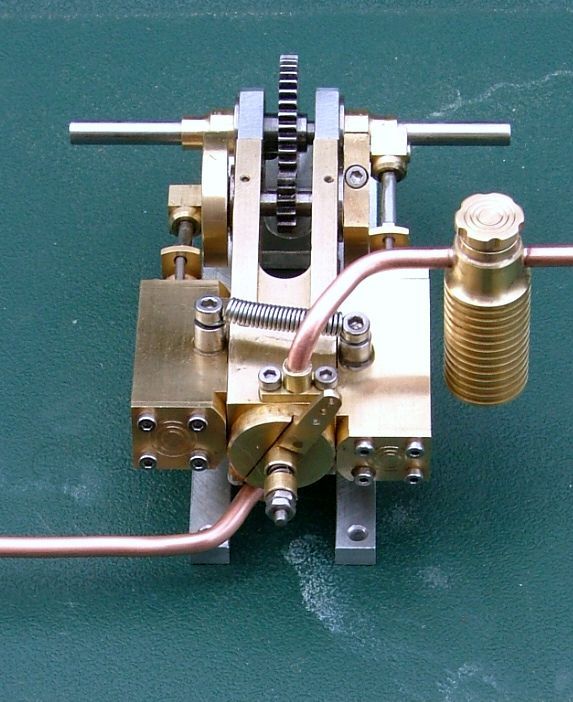
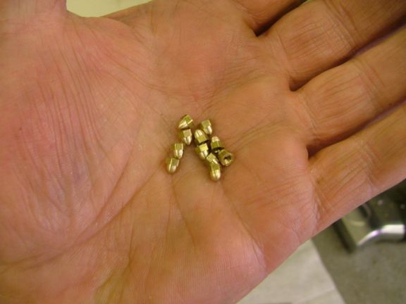
The connecting rods are supposed to be three pieces as drawn on the plans. That also requires bolts smaller than I have on hand so I opted to change the plans. I made the rods one piece and bushed both ends with brass. Since my crank shaft can be disassembled the rod bearing does not need to split. I was going to leave the rod squared off, but clearance in the crosshead guide was a problem so I had to back up and turn down the center section of the rod. I assembled what I have so far and spun it up with the lathe and lots of oil. It's a little tight here and there but that can be worked out.
Pete
View attachment ImageUploadedByModel Engines1483487095.216765.jpgView attachment ImageUploadedByModel Engines1483487112.805588.jpgView attachment ImageUploadedByModel Engines1483487134.343004.jpgView attachment ImageUploadedByModel Engines1483487147.067689.jpgView attachment ImageUploadedByModel Engines1483487162.574970.jpgView attachment ImageUploadedByModel Engines1483487199.432556.jpgView attachment ImageUploadedByModel Engines1483487251.066692.jpgView attachment ImageUploadedByModel Engines1483487268.590052.jpgView attachment ImageUploadedByModel Engines1483487283.049331.jpgView attachment ImageUploadedByModel Engines1483487293.383438.jpgView attachment ImageUploadedByModel Engines1483487304.571163.jpgView attachment ImageUploadedByModel Engines1483487315.355787.jpgView attachment ImageUploadedByModel Engines1483487349.461765.jpg
 

Attachments

  • ImageUploadedByModel Engines1483487219.258784.jpg
    60.6 KB · Views: 669
Looks great! Can't wait to see it under power. I've been following your project with interest and can't believe how small the components are! ��

Thanks for sharing. ��
 
Hi Pete,
Like a41capt I have been watching your progress, the engine is sure looking good.
Some times when you go off the drawing you have to improvise and most times it works out for the best.

I look forward to it's first steaming.

George.
 
Thanks guys, it sure is fun to share this stuff with people that have similar interests. When I try to show the wife and kids I get a collective " that's nice"
More progress - I guess these are cam followers ? A bit of a miss read of the print got me another deviation. The leg on the ring is supposed to be roughly twice as long to allow the valve connecting rod to thread into it and a jam nut secures it. Well I didn't want to waste the time and metal that I had in it so I am going with a stud in the ring with a jam nut sleeve to secure it. The rod will be drilled and threaded to mount on that stud and a nut to secure its position will be made to cover any gap and dress it up.
I thought that building off plans would be a piece of cake but turns out if you don't study the drawing carefully chaos quickly ensues !
Pete
View attachment ImageUploadedByModel Engines1483730828.412524.jpg
View attachment ImageUploadedByModel Engines1483730847.158174.jpg
View attachment ImageUploadedByModel Engines1483730890.224711.jpg
View attachment ImageUploadedByModel Engines1483730930.207302.jpg
View attachment ImageUploadedByModel Engines1483730946.241522.jpg
View attachment ImageUploadedByModel Engines1483730957.898530.jpg
View attachment ImageUploadedByModel Engines1483731038.720708.jpg
View attachment ImageUploadedByModel Engines1483731058.238726.jpg
 
Time to connect up the valve spool to the cam followers. Not much trouble here, but something must be a little off because with everything assembled there was a large increase in effort to turn the engine over. Turns out the alignment of the cam to the valve body needed work. I don't know if the drawings are off, it's hard to tell since at this point it could be a stack up of tolerances. I had to turn down the flywheel that dictates where the cam sits to move the valve bodies closer to the cylinder blocks. That fixed the alignment, just wish I knew what happened. I have cut all the parts to the sizes called for as close as I can pull off at least.
So that's most of the moving parts, next up is the steam control valve. That thing has a million holes in it !


View attachment ImageUploadedByModel Engines1484151280.735772.jpg
View attachment ImageUploadedByModel Engines1484151294.500098.jpg
View attachment ImageUploadedByModel Engines1484151305.785666.jpg
View attachment ImageUploadedByModel Engines1484151338.354379.jpg
View attachment ImageUploadedByModel Engines1484151353.649910.jpg
View attachment ImageUploadedByModel Engines1484151371.187183.jpg
View attachment ImageUploadedByModel Engines1484151388.752147.jpg
View attachment ImageUploadedByModel Engines1484151399.960879.jpg
View attachment ImageUploadedByModel Engines1484151417.311874.jpg
View attachment ImageUploadedByModel Engines1484151435.958301.jpg
View attachment ImageUploadedByModel Engines1484151451.557820.jpg
 
Hi Pete. I’m still following along. Between work and life in general I haven’t been able to get any shop time for myself so I have to get my hobby fix vicariously through others. The engine is turning out beautifully, there’s something about the symmetry I find very appealing.
I just wanted to say thanks for posting your build. I can appreciate the extra time it takes. Setting up a part, stop, take a picture, put the camera back into the “safe” zone, finish the part and repeat.

One day I’ll be able to get back into the shop and make some chips but for now thank you.
 
Bmac2 - thanks for the great post, it's funny to think I am doing something guys want to watch. I feel like a hack most of the time especially when I see the other projects on this site !!

It is surprising how much thought it takes to do a build thread. It's turning into a test for my iPhone on how well it holds up to metal bits and cutting fluids etc !
 
The steam control valve has been the part I have been not looking forward to from the time I first looked thru the drawings. I am not sure if I could have pulled off this part if it weren't for fcheslop's post back on post #20 that directed me to the drawings by Julius de Waal. Those drawings made the 31 hole locations much clearer, thanks again fcheslop !!!!!!

I started with a hunk of roundstock that was a bit big for the part but it was the closest stock I had around. I started with the face that needs to really smooth for the directional valve to rotate on and be fairly steam tight. From there it was a hole tapped for a shaft that the valve rides on and then into the mill to square it up. Back to the lathe to part off the block and then more mill work for the bottom relief. Once that was done came the intimidating job of all those holes. It's tough to drill into something I have so much time into ! I took my time and triple checked every dimension before sinking the drill bit into it. I made my own notes/drawings for each side just to keep my head clear on what I was doing. Looks like it came out like it should so I can quit holding my breath !!
View attachment ImageUploadedByModel Engines1484521162.157233.jpg
View attachment ImageUploadedByModel Engines1484521199.844703.jpg
View attachment ImageUploadedByModel Engines1484521214.418474.jpg
View attachment ImageUploadedByModel Engines1484521229.150287.jpg
View attachment ImageUploadedByModel Engines1484521243.360091.jpg
View attachment ImageUploadedByModel Engines1484521260.585952.jpg
View attachment ImageUploadedByModel Engines1484521295.533635.jpg
View attachment ImageUploadedByModel Engines1484521318.318871.jpg
View attachment ImageUploadedByModel Engines1484521332.734866.jpg
View attachment ImageUploadedByModel Engines1484521347.007017.jpg
View attachment ImageUploadedByModel Engines1484521359.637341.jpg
View attachment ImageUploadedByModel Engines1484521374.069655.jpg
View attachment ImageUploadedByModel Engines1484521387.920438.jpg
View attachment ImageUploadedByModel Engines1484521406.194270.jpg
View attachment ImageUploadedByModel Engines1484521421.478219.jpg
View attachment ImageUploadedByModel Engines1484521437.273130.jpg
 
Superb work Pete! I hope you show it installed and running your newest boat when completed.

Thanks for all the great documentation.

John
 
Thanks John !
Yep it will go in a boat when it's all done, but the boat doesn't exist yet. Not really sure what it will look like but it will be as small as I can make it and still be stable and pond worthy.

I will have the boat build and maiden voyage in this thread too.

Pete
 
This one is going to be pushed around with a prop, not sure of size or pitch though. The plans say a 30mm diameter but I'll see what I can learn about those when I get to that bridge.
Pete
 
The disk is pressed against the ports with a spring that is covered with a cup shaped piece of brass. This is going to have to be tested later to see if there is enough spring tension to make it seal. I'm sure it could be calculated, but I'm not your guy for that much math !
Pete

View attachment ImageUploadedByModel Engines1484787964.827730.jpg
View attachment ImageUploadedByModel Engines1484787982.748260.jpg
View attachment ImageUploadedByModel Engines1484787998.698802.jpg
View attachment ImageUploadedByModel Engines1484788009.235843.jpg
View attachment ImageUploadedByModel Engines1484788022.100610.jpg
 
Pete,

After making many dozens of this type of control valve, maybe I could give you a couple of pointers that 'might' give you a leak free valve.

If possible, lap the two faces together so that you get a nice flat looking face. You will see after you start where all the high spots are, and you keep going until you have a complete dull surface on both parts. Don't try to use power tools, your fingers are more sensitive when the correct surface finish is reached.

The spring loaded part is one area that is affected by vibration and your inputted rotation, so I would suggest you make the centre spindle a little longer so that you can use a locking nut on top of the nut that is on there, or make two very thin nuts so that they can be fitted into the space you have. I always tried to finish it off by using an acorn nut to do the locking, it looks much neater than just two nuts and are very easy to make.

This shows the locknut required

top%202_zps4xhjdkeh.jpg


And these are the acorn nuts, you make them to whatever length is required.

marcher64_zps3oli6knq.jpg


Just suggestions

John
 
John, I would like to know the details of how you do the lapping process. What do I need to do it properly ?
As far as the nuts go it would be good to make something a bit fancier wouldn't it.
Pete
 
Pete,
Because it is ali and brass you do have to take it steady.

I would start off with a tiny bit of valve grinding paste, but the very fine one. I would use that until you very nearly get to a full lapped coverage on both parts.
Once that is done, wash everything to as clean as possible, you don't want that grit working it's way onto the faces again. Then you could use a tiny blob of brass polish and carry on lapping, eventually, it should be perfect, but if you want to be even better, use a bit of toothpaste for final lapping. Once it gets to that stage, after you have cleaned the faces off, put a drop of oil on there and you should be able to pick the engine up by suction alone.

The lapping technique is to get the top part (brass) between your fingers, and like spinning a top, with slight downwards pressure rock the brass part backwards and fwds about 90 degrees, after a minute or so, rotate the top by 90 and then repeat the 90deg fwds/bk. Keep doing this for about 2 full revolutions and then see what the faces on the parts look like. Continue until, as I said, nearly having a matte surface all over, then go to your finer stuff.

John
 
Thanks John, that's a great explanation. I will look for the grinding paste and work on getting the surfaces right once I have all the parts made. I'm getting close to having something that will run on air so I want to drive on till it spins. I just have to make the plumbing fittings and bend up some little pipe and it should run. After that I'll back up and clean up my work. The plans call for a pretty fancy oiler, I have had good luck with the simple one I made for my other boat so I might just stick with simple.
Pete
 
Pete,

What isn't there can't go wrong, so simple is usually the best way.

If running on air, then a mechanical means of getting oil into the moving parts is required, but like you are going to do, a basic displacement lubricator should be perfect.

John
 
Back
Top