A small steam engine

Home Model Engine Machinist Forum

Help Support Home Model Engine Machinist Forum:

This site may earn a commission from merchant affiliate links, including eBay, Amazon, and others.
I think Rich is a little afraid to build an engine :hDe: He will take any chance to deviate from the engine project. First there were pages and pages of small boiler build. Beautiful I must ad. Now comes a thread on a small steam engine and again ..... boiler....piece of engine....control valve....what next. scratch.gif

Don't be afraid to build the engine. It will work fine, be beautiful and win project of the month for sure. Thm:
 
Hi

Thanks Paolo

Helder, what next, who knows, it's all good fun though. I decided to build this little boiler and wobbler because my time in the shop is limited to half hours here and there at the moment. I still need to learn a few things before I start on a decent engine to go with the horizontal boiler thats why I'm practising on this one. Later on this year I'll be able to have more time in the shop to concentrate and play with something a little more ambitious ;D ;D ;D. Meanwhile this will do to keep me going.

Cheers

Rich
 
Looking good sofar,Rich.
I have one small remark.With the little handwheel,I would put the locknut on first,and then the handwheel on top.Tighten nut against handwheel,and it's out of sight.Just a thought.
Regards.Hans.
 
Hans has a point there. There is no need to hide the hand wheel behind a nut.
In relation to what I said, just kidding. I too, many times go a long way "around the bush" before reaching the final objective. Especially when I make something to sell, when it goes away it seems that something inside me goes with it. ;)
 
Noitoen said:
Especially when I make something to sell, when it goes away it seems that something inside me goes with it. ;)

Ah, I know that feeling. Over the years I've sold 3 or 4 of my engines, and come to regret it every time.
 
Hi

Good idea Hans, on the final assembly I'l try the nut underneath. I don't have a piece of brass suitable to make the cylinder as yet, thats another reason I have drifted off a bit. I hope to get some at the weekend so I can continue with the engine.

cheers

Rich
 
Hi

I haven't had the opportunity to spend much time on this project of late, my apologies to any who has been waiting.

I made one small part tonight, the bush for the crankshaft. Its a straightforward turning job from a piece of 3/8 round brass. the photos and drawing should be all that's needed for this part. Aim to get a good light push fit in the frame.

Turn, drill and ream.

DSC08441.jpg


Part off.

DSC08443.jpg


The finished bush.

DSC08445.jpg


Fitted in the frame.

DSC08446.jpg


DSC08447.jpg


I have finished a couple of drawings of the cylinder and cylinder cover. The first is actual size while the second is enlarged. Easier on old eyes. I'm fairly confident that I have got all the dimensions right.

cylindercover.jpg


cylindercoverenlarged.jpg


Cheers

Rich

 
Rich,

Not been on here for a while, looking good ... and another boiler! That one seemed a doddle to you, think you're becoming an expert!

Nick
 
Hi Nick

An expert ::) ::) ::) I don't think so, but the more I do the more confident I become.

Anyway heres the cylinder. The plan calls for a cylinder of 1/2 inch by 5/8 by 1 1/16. I have a piece of brass 5/8 x 5/8. Cut off a piece 1 3/16 long. Chuck in the 4 jaw and face one end. It doesn't have to be exactly centralised for this operation. then turn over and face the other end and turn to size.

DSC08389.jpg


set up in the mill and using an edge finder, I use a laser, set the DRO (or dials) to zero.

DSC08391.jpg


Centre drill the 4 stud positions.

DSC08394.jpg


Then lightly centre drill the cylinder bore centre.

DSC08395.jpg


Drill the 4 stud holes tapping size for 10 BA.

DSC08396.jpg


Then tap 10 BA

DSC08397.jpg


Centre the cylinder in the 4 jaw chuck. If you go to the TIPS AND TRICKS section of this forum and look at CENTREING A 4 JAW CHUCK you will see the piece of kit I have just made which makes the task of centreing very easy and accurate. Then drill the bore slightly under size.

DSC08401.jpg


Then ream 3/8

DSC08402.jpg


The cylinder almost done. I have to reduce the width to 1/2 inch by milling 1/16 off each side.

DSC08404.jpg


On the plans I have it shows the cylinder as made in one piece by carefully drilling, boring and reaming a blind hole. This would save the trouble of making the cylinder cover and studs etc.

Cheers

Rich
 
G'day Rich,

Nice work so far! Very informative :)

Just on your last note though: The plans for my first engine (an oscillator) called for a blind bore of 5/16". From memory we had a bu%%#r of a time getting it 5/16" all the way through. Ended up grinding down the tapered section of the hand reamer. I've avoided such problems ever since! I reckon the cylinder covers are a MUCH better idea ;D

Keep up the good work :)

Gordon
 
I have done oscillators with blind bores before also but I think it's better practice to bore all the way through and use a cover. I always do it that way now.
 
Nice work. :bow: Whenever I have machined cylinders with a cover involved, I found it best to make both parts and then mate them up and drill the assembly in situ. That way there are no variances between the holes. Once the tap drill has been used, I remove the cover and open out those holes with the proper clearance drill. Of course I mark the orientation of the pieces so that they can be assembled back together the same way every time. This process has saved me from oval-ing out the one hole that always seemed to 'stray' out of alignment. But then again, I am old fashioned and set in my ways. ::)

BC1
 
Hi

Imade the cylinder cover tonight. A piece of 1/2 inch square brass is chucked and faced then set up in the mill and with an edge finder a datum found. 4 holes are centre drilled and a centre drill in the centre. The 4 stud holes are drilled clearance for 10 BA.

DSC08421.jpg


The part is then returned to the 4 jaw and centred as described earlier.

DSC08423.jpg


The 1/32 boss is then turned.

DSC08427.jpg


Then parted off.

DSC08429.jpg


DSC08430.jpg


This is the set up I used to make some 10 BA stud . I used 1/16 stainless steel to make the stud.

DSC08436.jpg


DSC08437.jpg


Screw a length of stud in with a brass nut and cut off with dremel type tool. The studs are over long at the moment, I will trim them down on final assembly.

DSC08438.jpg


The cover fits well, all the holes line up ok.

DSC08439.jpg


Cheers

Rich
 
Rich,

Good stuff. Did you use the DRO to locate the holes? I always struggle getting them to line up properly and end up going a size up with the clearance hole! Suppose I should use the method of clamping and drilling through everything or turn the register , drill holes then part of cover from same stock before opening up!

Nick.

ps. I reckon it'd look better if all those studs were cut the same length! ;)
 
Hi

Nick, I use a laser edge finder. They are brilliant. I have used the sort that puts a light on when it contacts an edge, DTI's and wigglers but the laser is by far the best. Where the red dot is that is the centre. You don't have to half anything or make any calculations, just zero your dials. Less than half a thou accuracy. I zero on one corner of the workpiece and then work from there. The studs will be cut to length on final assembly as stated above.

Tonight I made the piston. Well almost made the piston, there is still some work to do on it.. On the plans I have it shows making the piston from brass and the conrod seperately and screw them together. I have made mine in one piece from stainless steel.

Chuck a piece of 3/8 stainless steel round bar and mark roughly where to turn to. Centre drill the end and support with a revolving centre. I have already checked that the 3/8 will not quite go in the bore.

DSC08448.jpg


Turn down to 1/4

DSC08451.jpg


Run in with a parting tool to leave 1/8

DSC08452.jpg


Turn away the central part to form the conrod.

DSC08457.jpg


Grind a tool and cut the 3 oil grooves.

DSC08459.jpg


Part off

DSC08463.jpg


Reverse in the chuck and turn the piston to size. The big end is still over long with the centre drill still in it at the moment.

DSC08465.jpg


The piston only needed a light touch with wet and dry spinning in the lathe to get a nice fit in the bore.

DSC08466.jpg


DSC08467.jpg


Cheers

Rich
 
Hi

I have finished the piston and conrod. Take a look at the drawing first.

DSC08494.jpg


On the plans that I have it says take the measurement from the top of the piston to the centre of the crank pin. As you will see from the following photos, with the set up I used to mill the flats on the con rod I couldn't get at the top of the piston to find a datum. Had I measured the piston length accurately first I could have drilled the crankpin hole at the same set up by using the bottom of the piston as a datum. As it turned out my piston is .501 so I could have done it.

Set up in the rotary table and tail stock to mill th flats.

DSC08477.jpg


Mill the first flat then turn 180 degrees and mill the second flat.

DSC08482.jpg


Set up in a V block to drill the crank pin hole.

DSC08484.jpg


Centre drill

DSC08490.jpg


Drill.

DSC08491.jpg


Then finally ream 1/8

DSC08492.jpg


The finished pisto and con rod.

DSC08494.jpg


Cheers

Rich
 
Hi

I machined the cylinder to the required width of 1/2 inch.

DSC08498.jpg


DSC08501.jpg


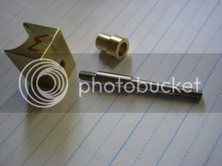
The pivot will be made from 1/8 stainless steel. I need this to be a good fit in the 1/8 hole that will be drilled in the cylinder so I did a test drill on some scrap ally first. Drilled under size then finished with an 1/8 end mill.

DSC08502.jpg


Its a good fit.

DSC08504.jpg


Make the pivot.

DSC08517.jpg


Set the cylinder up in the mill and use an edge finder to get a datum. You can just see the laser red dot on the edge of the cylinder.

DSC08506.jpg


Centre drill.

DSC08507.jpg


Drill.

DSC08508.jpg


Finish with the end mill, 5/32 deep. Don't go right through into the cylinder.

DSC08509.jpg


Machine away the cylinder face.

DSC08513.jpg


DSC08515.jpg


The pivot pushed into the cylinder with flux and a small amount of silver solder wire.

DSC08518.jpg


In the brazing hearth.

DSC08520.jpg


Even though the pivot was a tight fit in the cylinder, after silver soldering I tried it in the frame only to find the two faces weren't parallel. I drilled a 1/8 hole through some scrap all and clamped it to the cylinder then re-heated to melt the silver solder and align the pivot.

DSC08521.jpg


I'm not completely happy with the outcome. The piston wouldn't fit in the cylinde so I had to ream it out again. The piston now fits but its not as good as it was in the first place. If I were to make the cylinder again using this method of construction I would make a jig to hold the pivot true while I silver soldered it in place. I think a better way would be to cut a couple of threads on the end of the pivot and tap the cylinder. Then assemble the cylinder/pivot/frame together with spot of loctite on the thread. This would ensure that the two faces meet accurately.

The original plans call for the crank pin to be 3/32. I don't have a 3/32 reamer so I upped the size to 1/8, a reamer size I do have. This means that the drill jig will have to be modified. To re-locate the hole I set the jig up loosely in the mill. With a centre in the quill bring it down till it enters the hole and centres it. Then tighten the hold down clamp. Drill and ream the jig 1/8.

DSC08523.jpg


Place the jig on the pivot and push a piece of 1/8 rod through the jig and the crank pin hole.

DSC08524.jpg


DSC08525.jpg


Set up in the mill. A short piece of copper tube with a nut and washer holds the jig still.

DSC08526.jpg


Drill the 1/16 hole.

DSC08530.jpg


A test fit in the frame. The holes line up perfectly.

DSC08532.jpg


Cheers

Rich

 
Sorry things didn't work out as planned Rich ???

Here is a photo of my current build that is similar:

IMG_6627-1.jpg


The original plans called for the pivot to thread into the cylinder, but my version is altered slightly. I made the pivot shaft a little larger diameter through the bushing, thinking it would carry the load better, but it also provides a square shoulder to the cylinder face which should help keep things square. The actual cylinder is a piece of tube to be brazed onto the piece in the picture. The major diameter of the pivot is 0.187" and both threads are 6-32.

Keep up the nice work!
 
Hi Jeff

That looks to be a better idea, along the lines of what I had in mind. The pivot could be soft soldered in I suppose which would require less heat but would still need a little jig of some sort to ensure a perfect angle. My cylinder/pivot will work ok I think, its just disappointing when you have spent quite a bit of time making a part that things don't work out as planned.

Cheers

Rich
 
Back
Top