A new look at Opposed Twin I.C. Engine

Home Model Engine Machinist Forum

Help Support Home Model Engine Machinist Forum:

This site may earn a commission from merchant affiliate links, including eBay, Amazon, and others.

Brian Rupnow

Design Engineer
Project of the Month Winner
Joined
May 23, 2008
Messages
14,963
Reaction score
8,238
Location
Barrie, Ontario, Canada
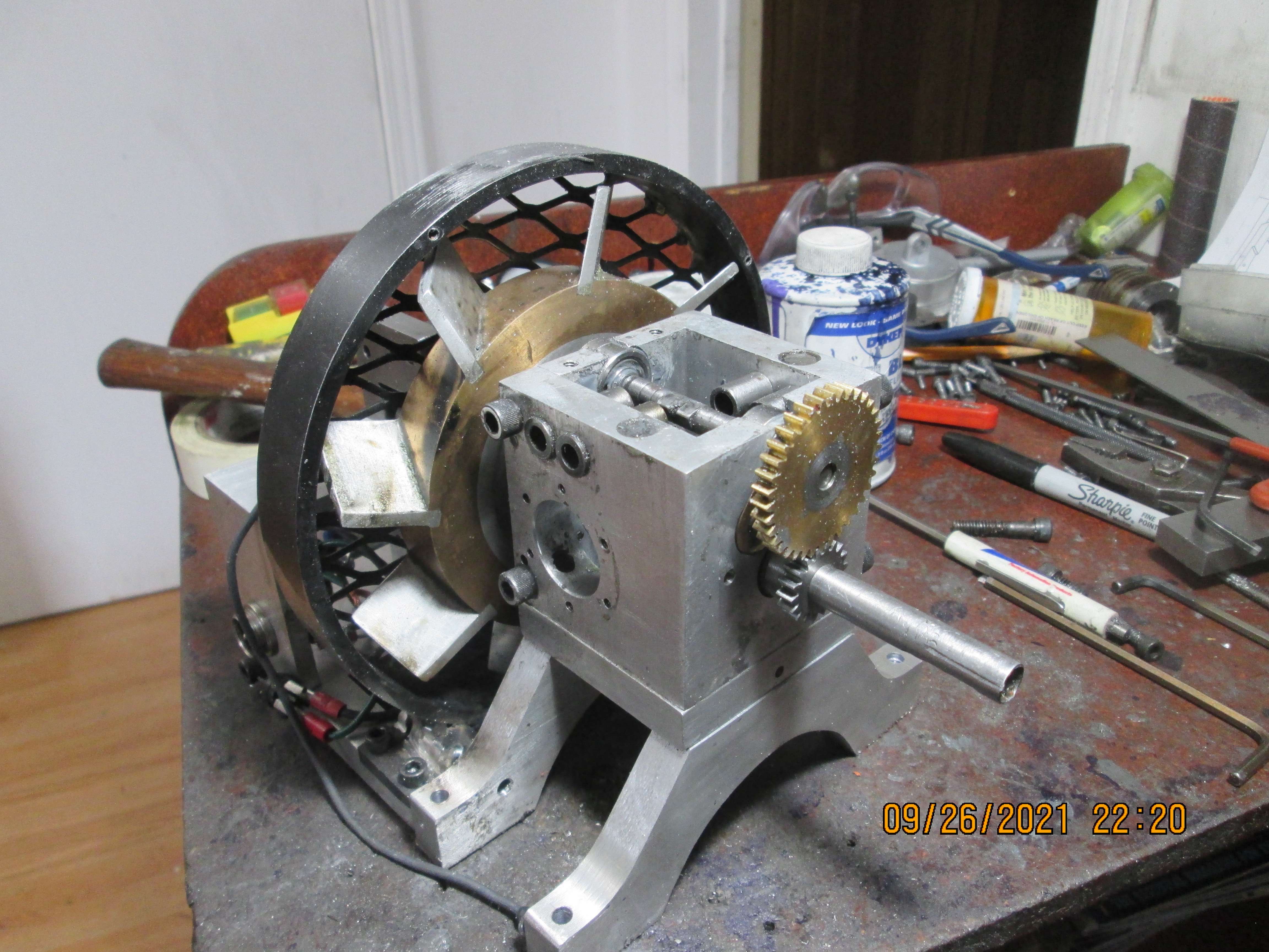
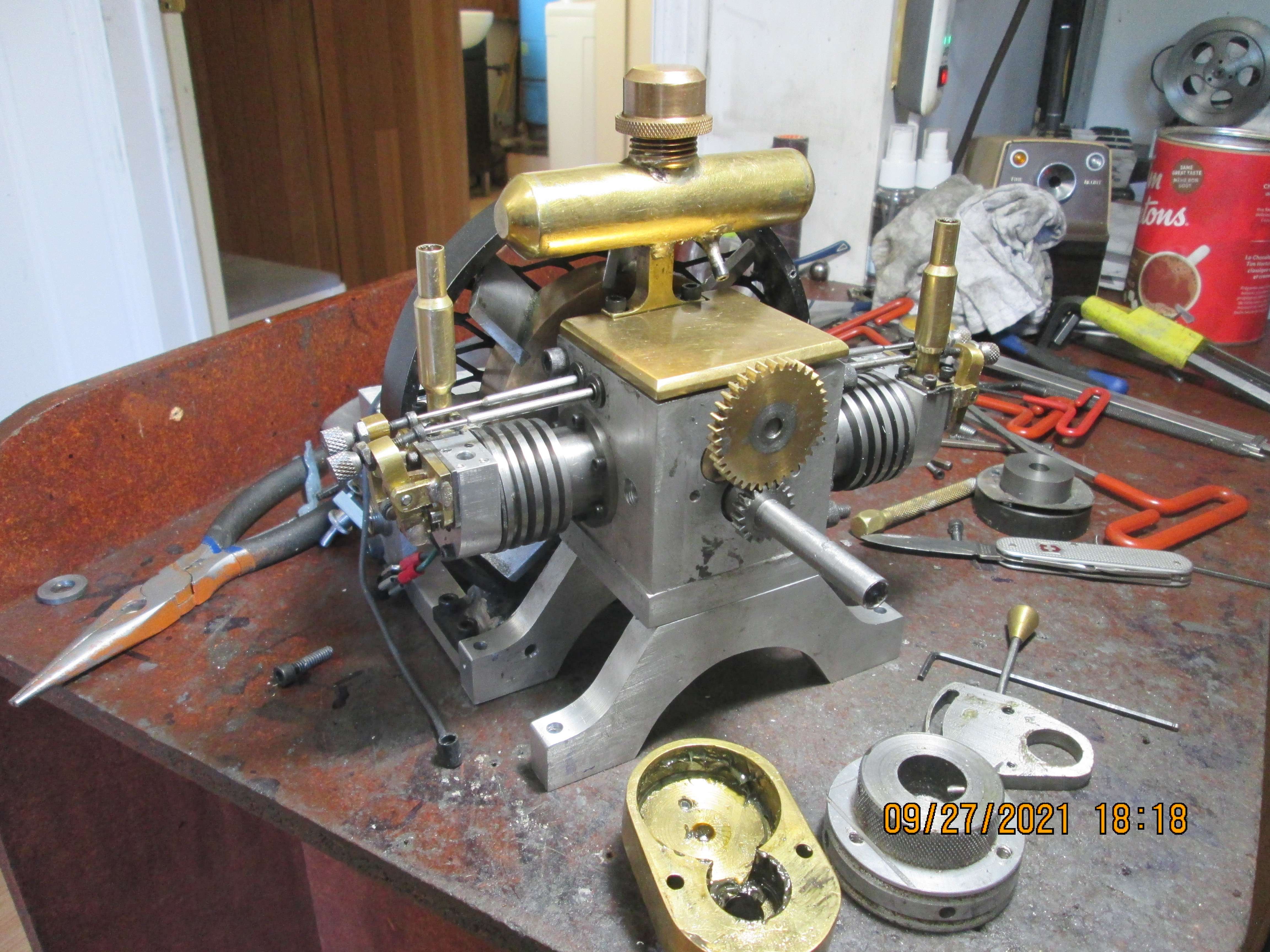
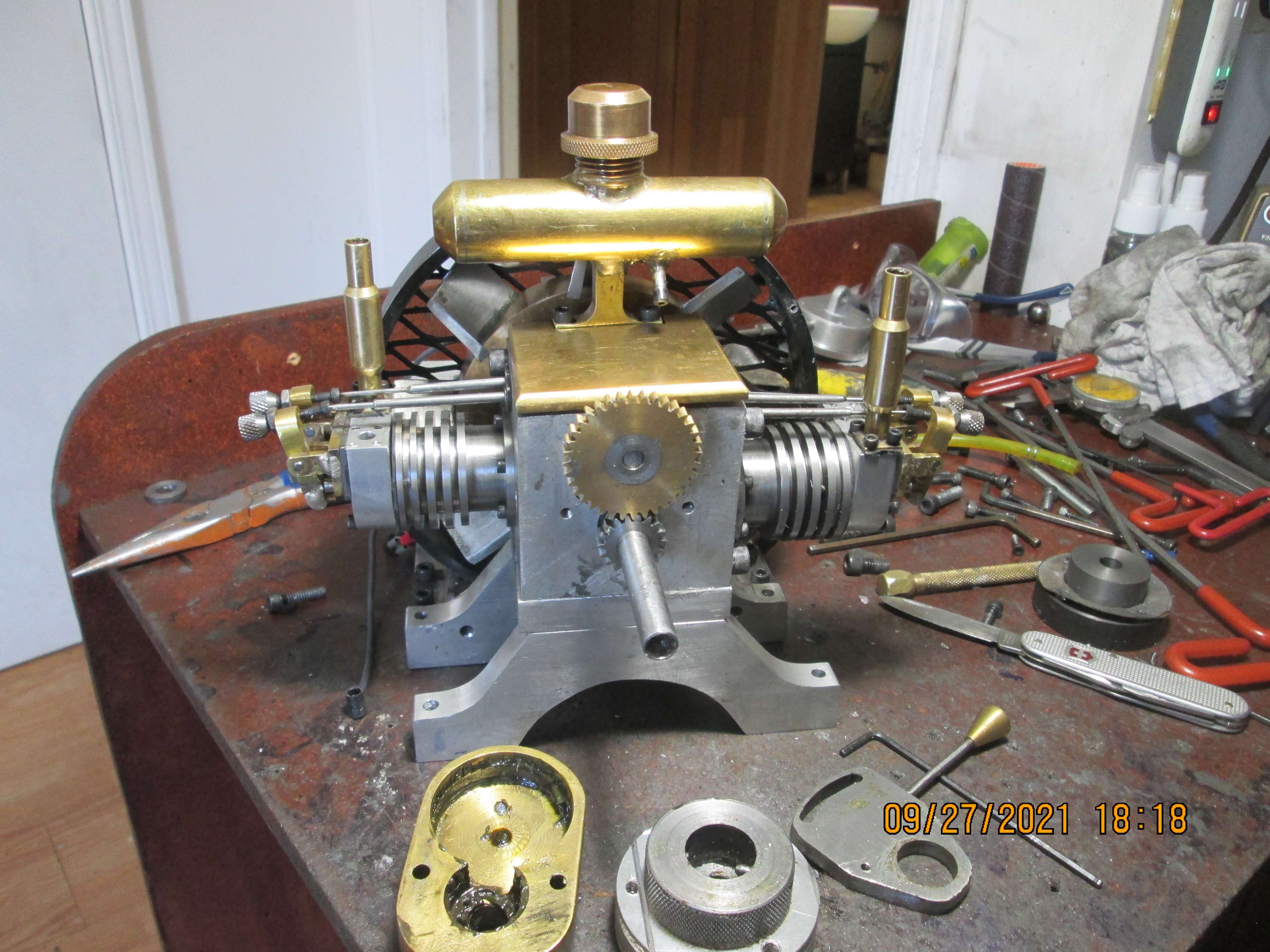
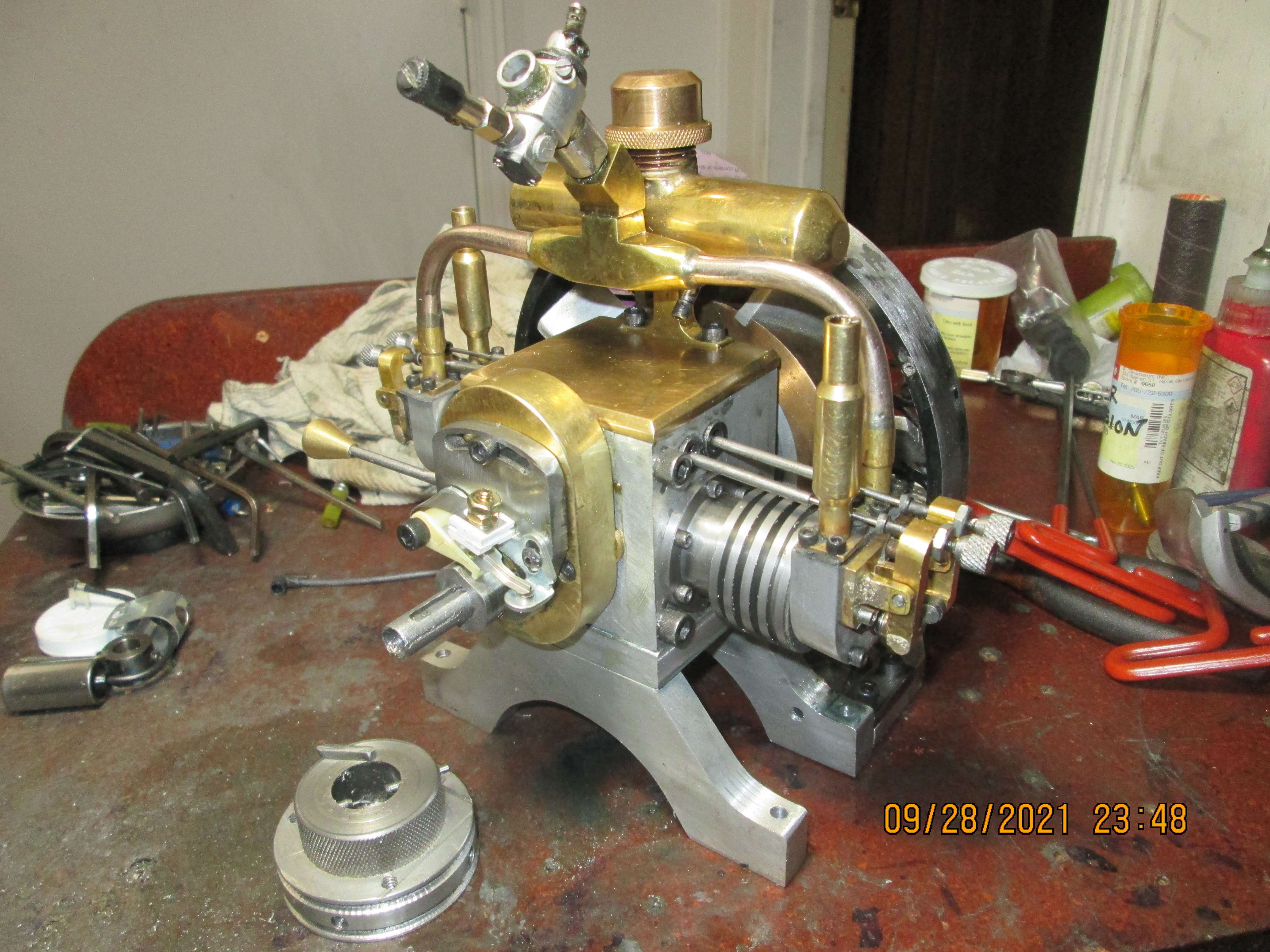
A few years ago, I built my version of an opposed twin i.c. engine. It ran very well, and I was very pleased with it. There was always a problem with the configuration of this engine, because the sparkplugs were at the very bottom of the horizontal cylinders, and if you happened to flood it while starting it, you could crank all day and it wouldn't clear itself. However, it did run, and I made some good videos of it running. The crankshaft was riding on bronze bushings, and the crank wasn't "dead nuts" straight. I was using my standard 1975 Chrysler ignition points, and a cam running on the crankshaft. As time went by, with more and more hours running time accumulated on the engine, the bronze crankshaft bushings began to wear, cause by the crank that wasn't truly perfect. It wasn't a wet sump engine, so that didn't really matter a lot ---BUT--as it wore, the ignition cam, attached to the crankshaft began to move around with the sloppy crankshaft. Finally, the ignition cam on the less than perfect crankshaft was moving around enough to seriously affect the timing and spark of this engine. This took me the longest time to figure out what was going on, and when I did figure out what was happening the engine went "Up on the shelf". I promised myself at that time that eventually I would redesign this engine, using ball bearings on the crankshaft, a crankshaft that was truly straight, and a configuration which put the sparkplugs at the top of the horizonal cylinders. I would be able to re-use the cylinders, cylinder heads, overhead valve mechanisms and valves and cams, while making a new central crankcase and fan assembly. This is early days yet, and I still have some unanswered questions about the T head engine I have currently been building, but I think this will be the direction I move in next.
J9oMYj.jpg
 
I'm glad you're revisiting this engine, Brian. I followed the original build and I really liked the whole concept. I'll be looking forward to seeing how it turns out.

--ShopShoe
 
This is interesting because I built the Upshur version of this engine and never got it to run properly. I just got it back off the shelf last week to try again. I believe that the biggest problem with this version of the engine is the valve timing. It uses only two cams so that the intake of cylinder #1 and the exhaust of cylinder #2 uses one cam and the other cam runs #2 intake and #1 exhaust. The problem is that if you adjust the intake on one cylinder it changes the exhaust on the other cylinder. There is really not enough room to use four cams. I will have to take a closer look at your original design but a quick glance it looks like you used two cam shafts with an idler gear.
 
This is interesting because I built the Upshur version of this engine and never got it to run properly. I just got it back off the shelf last week to try again. I believe that the biggest problem with this version of the engine is the valve timing. It uses only two cams so that the intake of cylinder #1 and the exhaust of cylinder #2 uses one cam and the other cam runs #2 intake and #1 exhaust. The problem is that if you adjust the intake on one cylinder it changes the exhaust on the other cylinder. There is really not enough room to use four cams. I will have to take a closer look at your original design but a quick glance it looks like you used two cam shafts with an idler gear.
My Upshur twin uses one cam lobe for both intake valves and the other lobe for both exhaust. plans are dated 2001.
 
Yesterday I was prowling thru the drawings and models of this build, and I discovered something good. I have been thinking all along that I would probably have to build a new crankcase, and probably new cam and crankshaft.---However---Taking a much closer look, I may be able to modify the crankcase to take sealed ball bearings on both the crankshaft and the camshaft. If so, that would be a real bonus.
 
This is what some research showed me. At the bottom of this model you see the original crankcase "as is" with a round blue insert on one side to hold the crankshaft bushing and a bushing on the opposite side to hold the the other end of the crankshaft. You can also see a strange shaped red insert on the near side that was the camshaft bushing, with a plain bushing on the far side to hold the other end of the camshaft. The round yellow cylinder represents the outer diameter of the crankshaft bearing, and the green cylinder represents the outer diameter of the camshaft ball bearing. At this point, I believe that I can rework the crankcase to accept ball bearings for the crankshaft and for the camshaft. This would let me keep the original crankshaft and camshaft, which would be a tremendous bonus.
wBJ9bK.jpg
 
So yes, it can be done. I have been holding off on this project, wanting to completely finish the T-Head engine before wading into this. The T-Head is essentially finished, and my new bandsaw is installed and working, so I think I will be making chips with this rework of my opposed twin engine.
66RAf6.jpg
 
I'm having a quiet day, tearing down the old engine. I gave myself a terrible flash yesterday with my old A.C. welder, and my eyes are howling about it. The new helmet I got when I bought my tig welder has a sensitivity dial on the side of the helmet, and somehow the dial had been turned to '0", so when I started to weld the lens didn't automatically darken. As I begin removing pieces from this engine, I am impressed by how many machined parts there are, and beginning t wonder if I should just buy some angle of the correct size and make a new crankcase.---Not sure yet.
o8bnsr.jpg
 
So, here we are, right down to the nitty gritty. I guess the most surprising thing I have seen is how incredibly dirty everything was. Lots of grease and oil and sludge. I don't know how long ago it was that I designed and built this engine, but it's been a few years. I see a few simple things that I would change a bit if I was starting to build this engine from scratch now, but really not much. I can bore straight thru the large top-hat that supports one end of the crankshaft and out thru the other side of the engine in one set-up. The engine is 2.75" out to out, and the stroke on my mill quill is 3.00" The cam bore will be a little more difficult because the tappet guides are loctited in place and there is only 0.632" between the inner ends. The ball bearings for the camshaft are 0.750" o.d.---I can probably put a bit of heat on the tappet bushings to release the loctite and take them out until the camshaft bearing bore is completed and then loctite the bushings back into place. Actually. the bore for the camshaft bushings is only 0.75" so I would probably just run a 3/4" reamer thru there.
OMJxVm.jpg
 
All four ball bearings have been installed, two on the camshaft and two on the crankshaft. I still have some spacers to make and will put up a picture after they are installed.
 
I built the Upshur twin and my biggest problem to getting it run was to discover the spark jump to the push rods.
Once the plugs were booted it run with no problem.
 
I built the Upshur twin and my biggest problem to getting it run was to discover the spark jump to the push rods.
Once the plugs were booted it run with no problem.
I built the Upshur twin several months ago and cannot get it to run at all. I put it aside a few months ago and got it back out last week and I am at a loss to find the problem. I have checked everything I can think of but nothing seems to work.
 
So, here's a picture of the crankcase with all ball bearings installed. There isn't that much that you really can see. I had to open up a few counterbores and make some bearing spacers, but it's all done without having had to change the overall shape and dimensions of anything. The camshaft bearings set about 0.020" proud of the top surface, but that isn't a problem, as there is a magnetically attached plate over that top surface when everything is put back together. I am so happy that I didn't have to make a new crankshaft o camshaft.
PzHSWj.jpg

AsiAFX.jpg
 
I have never been happy with the base I made for this engine. I am going to build a new, much shorter base because I think the proportions are better.
xybsCH.jpg
 
Today I shortened the plate directly below the crankcase, and machined two new "feet" that are much shorter than the original ones. I stuck that evil looking flywheel/fan on just to make a good picture.
SXoJiD.jpg
 
Today I reworked the flywheel/fan guard to fit the shorter engine base. Also took the opportunity to J.B. Weld shut a bunch of holes I had drilled in the guard to mount a governor. The governor kinda sorta worked, but I could never get the engine to run consistently long enough to get the governor tuned properly. I may still try a governor to control this engine, but if so it will be mounted on a separate base and connected with an o-ring drive belt.
Q2p0uY.jpg
 
Well, that's a day out of my life, but it's been a good day. There was no way I could rework the coil mounting and switch bracket to make them work with the new engine frame, so I built new ones---and modified the guard for the wicked flywheel/fan to fit the much shorter engine base. Everything looks a bit rough right now, but I haven't done my cosmetic magic yet. Tomorrow I will tidy things up a bit, and see what's involved with mounting the gas tank and cylinders---They should just be direct bolt ons.
VU94Kw.jpg

2Zpa0x.jpg

tgHbjQ.jpg
 
Today seen the cylinders cleaned up and reinstalled, along with the pistons and connecting rods. I could have used one of Chris's elves to get down into the crankcase and tighten the rod bolts. I had forgotten just how inaccessible they were when the bottom plate was installed on the crankcase. I had to take everything apart to get at the rod bolts to tighten them. Before I go any farther now, I have to time my valves before my gear cover goes back in place.
0Mel9d.jpg

IRMku3.jpg
 
--I just spent an hour reading thru all the posts made on the forum when I originally built this engine, and I discovered something. On the original build, that diamond mesh on the flywheel guard was between the flywheel and the engine. Now it's on the other side. Ah well, I didn't plan on sticking my fingers in there anyways.
 
So, here we are, all reassembled. Crankshaft and camshaft are both riding in sealed ball bearings. That lever at the very front of the engine has my ignition points mounted on it, so I can adjust the timing by lifting the lever up or down. The plate will rotate to the limits of the curved slot, letting me fine tune the timing while the engine is running. That knurled pulley and key setting in front of the engine go on last, as it has part of my starter which I engage with my variable speed drill. I still have to remove the fan guard and give it a bit of cosmetic work and a new paint job. I might machine a swoopy looking air horn to fit on the intake side of the carburetor. Tomorrow I have some real, paying design work, so I probably won't post anymore progress for a couple of days.
fdscmO.jpg
 
Back
Top