On two previous engines I have used purchased cast iron rings. They both performed very well. I am at a loss why this engine has no compression when dry, and by dry I mean no pool of oil setting on top of the piston. I have just looked in detail at both previous engines where the purchased rings worked fine, and in both cases I see that I lapped the cylinder with the piston which was to be used in the engine, then added the rings to the piston afterwards. On this current engine where I am having so much difficulty, the piston was deliberately machined to 0.002" less than the cylinder bore. On my engine "Thumper" I made a note to myself saying that even though I had used the piston to lap the final cylinder bore, it wasn't a tight enough fit to run without the rings. There is a lesson for me there. Even though I have read in numerous places that the piston should be 0.002" smaller than the cylinder bore, that doesn't work for me. I just paid $32 for another piece of cast iron 2 1/2" diameter x 4" long to make a new cylinder. I will bore it to almost final size, then use my new piston to lap the bore to final size.

You are using an out of date browser. It may not display this or other websites correctly.
You should upgrade or use an alternative browser.
You should upgrade or use an alternative browser.
A new attempt at making piston rings
- Thread starter Brian Rupnow
- Start date


Help Support Home Model Engine Machinist Forum:
This site may earn a commission from merchant affiliate
links, including eBay, Amazon, and others.
The 1.000" rings need to be used in a 1.000" cylinder bore in order to seal properly. If you do the math to compute the leak created by a .999" ring in a 1.000" bore and then compare that with the leak created by a .004" ring gap in a properly fitted ring/piston/bore, you'll find the leak created by the poorly fitting ring is 400 times greater than that of the ring gap.
If your previous 'successful' rings were used in a cast iron cylinder on a cast iron piston that was lapped for a very close fit inside the bore, then the rings probably weren't actually doing anything for you since the sealing was between the piston and the bore.
Aluminum pistons, however, need to be a couple thousandths smaller than the cylinder bore because the aluminum will expand faster than the bore and wind up seized inside it. The cast iron rings on them though still need to be the same diameter as the bore but they need a tiny gap to prevent them from being broken by differential expansion between them and the cylinder. The top rings will always expand more than the much more massive cylinders. - Terry
Last edited:
Terry--Everything you have said makes sense. I am currently making a new cast iron cylinder and hoping to use my new rings and piston in it. I have removed the rings from the piston until I finish the bore on my new cylinder. I currently have a new piece of cast iron up in my lathe and am closing in on the correct diameter bore. I currently have the bore down very close to that last 0.001" of diameter, and am proceeding with great caution not to overbore it. I will complete the new cylinder tomorrow morning. How much clearance to you recommend on a cast iron piston in a cast iron cylinder?---Brian
I assume you're lapping that new bore to its final diameter. I've never used a cast iron piston in a cast iron bore, but I assume the same clearance as used for an aluminum piston would be just fine. - TerryTerry--Everything you have said makes sense. I am currently making a new cast iron cylinder and hoping to use my new rings and piston in it. I have removed the rings from the piston until I finish the bore on my new cylinder. I currently have a new piece of cast iron up in my lathe and am closing in on the correct diameter bore. I currently have the bore down very close to that last 0.001" of diameter, and am proceeding with great caution not to overbore it. I will complete the new cylinder tomorrow morning. How much clearance to you recommend on a cast iron piston in a cast iron cylinder?---Brian
I ran a 3/4cc diesel model for a few minutes before it "ran-in" and "wore-out". It had a cast iron piston in a cast iron bore at sliding clearances. - as Brian's lapped piston. The piston will get hotter and expand more than the cylinder, but at model sizes (1"dia.), less difference that you can probably measure. If too tight it may tighten a bit, but rarely seize, but a good lap will make it the right size. (less than 0.001"?). But 2 good laps will make it too big.
Or so I was taught in the 1960s, when we still had some engines to re-bore that had cast iron pistons. It was my job to hone the bores "size-on-size" to the pistons, after cleaning any surface rust staining from the piston with 400~1000 grade emery. It isn't aluminium so doesn't expand enough to "fit when hot" to need such big clearances - it will just slap loudly....
But I have only experience of a few small infernal combustion model engines...
K2
- Joined
- Jan 4, 2011
- Messages
- 1,332
- Reaction score
- 343
I find this discussion interesting and confusing. Some folks are insisting that everything MUST be held within .0005. Obviously if that were strictly true many of the folks here would never get a running engine. Many are working in a home shop with old or less than precision equipment and their only means of measuring things are a dial caliper and seat of their pants. Some are saying that the the ring must be a minimum width and other say that is not important. Others say the the thickness of the ring must be absolute minimum not more than the width and others say it does not matter. Some are saying that the finish on the side and bottom of the ring groove must be highly polished and very precise and others are having success with less than precise operations. Obviously most of us are working with less than ideal equipment using manual machining and not a lab quality shop. Looking at engines built by some of the old timers like Rudy, Elmer etc. using old worn equipment in a small shop it is interesting how successful they were.
I am not criticizing any of the folks contributing here but obviously ring making theory is not an exact science. There are articles and videos showing successful results using everything from very crude to super precision.
Gordon
I am not criticizing any of the folks contributing here but obviously ring making theory is not an exact science. There are articles and videos showing successful results using everything from very crude to super precision.
Gordon
leerkracht
Active Member
Finally
all you need to know about piston rings
https://www.ms-motorservice.com.tr/...Piston-Rings-for-Combustion-Engines_53094.pdf
all you need to know about cast iron > stres relieving and temp range
https://www.ductile.org/didata/Section7/7intro.htm#Critical Temperature
the engines I designed and made are two 12 cylinder engines bore 24 mm with overhead camshafts
two radial engines 7cil and 9 cil al works fine
the rings are made the Trimble way nodulair cast iron GGG 40 (meehanite ) ring section 1x1mm
cast iron GGG40 liner min 24 mm max 24.02mm nominal lapping toolmarks free not honing , my opinion is you dont need the croshatch pattern (injection pumps have also no pattern and are very smooth ) under a magnifying glass you can see small spaces between the nodulair molecules and this is where the oil can settle
0.02mm taper for the cilinder boring is no problem (smal dimension on top ) some modelengines have a taper boring for max rpm and power due less friction at the end of the power stroke
rings are 0 to 0.02 mm greater than cilinder bore cut by an 0.2mm thick sawblade > ring clamped in a fixture not a vise
als mentioned section 1x1mm ( for 24mm to 26 mm bore ) thicknes 1mm+0.02mm for flat lapping in a ring holder on a flat plate grinding pasta 600 grid
heat treatment in a closed cylinder fixture(for ring gap of 2.5mm )(see article George Trimble) 800 ° C )
when the ring is closed in the cilinder boring you notice that the ring gap is almost 0mm due to material growth Now you can check with backlight whether the ring fully touches the bore. (most of the time 95% of the rings are good ) bring the ring gap to 0.1mm to 0.2mm for oil blow by if you need
modern cars also have low section rings (and low tension also for less friction)
The japanese manufacturer of model OS engines>> OS rings for four stroke engines (bore 24mm are 0.2mm gap wenn new )
pistons are 7075 T6 dimention 23.95mm (better are high silicone pistons) groove with = ring +0.02 mm (not a sloppy fit )
these combination works for me ( i run mine on methanol and 4% Klotz oil )
thats for now
enjoy
video 12 cilinder
7cilinder radial parts
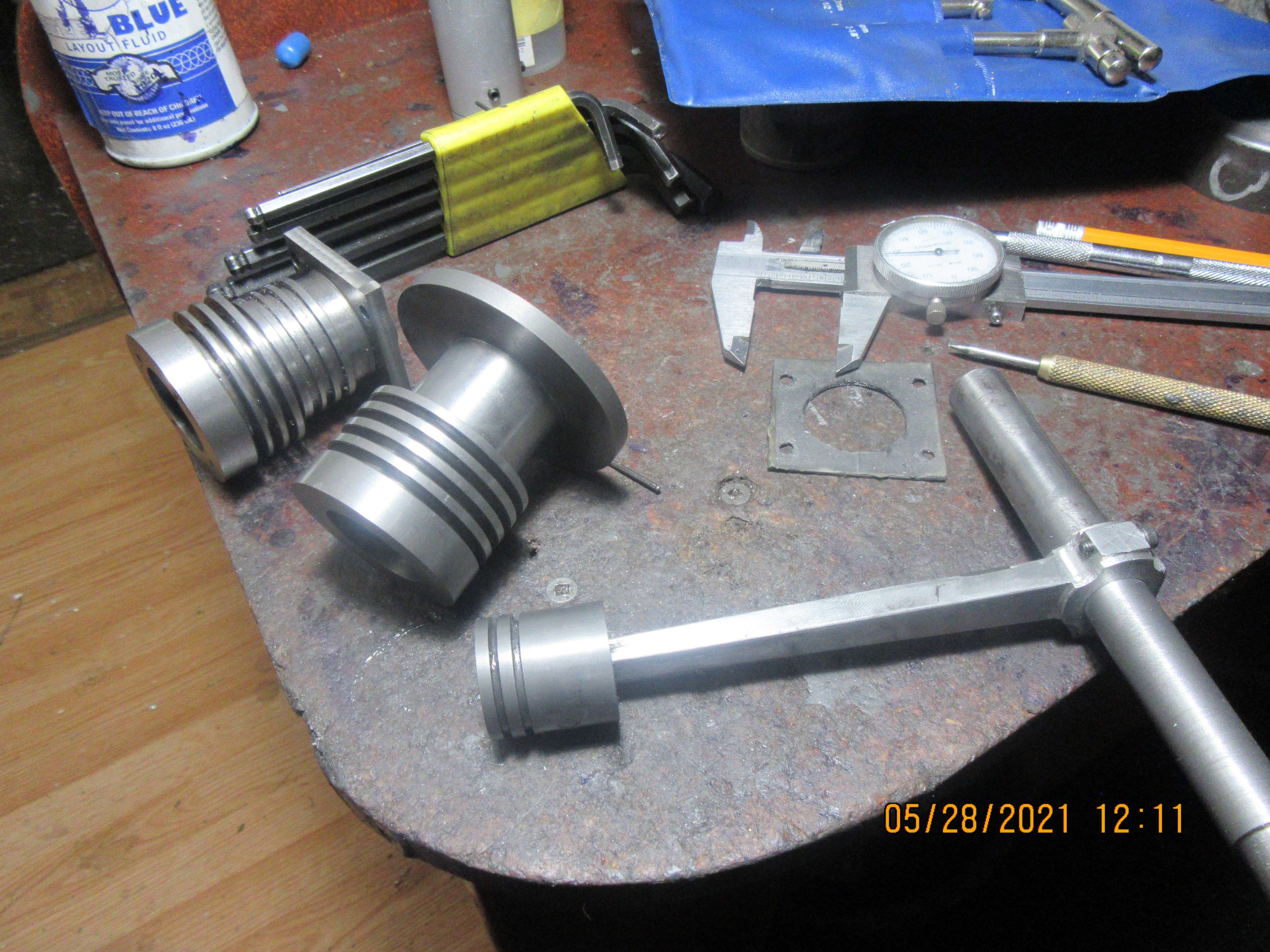
So here we have it---Old cylinder in background, new cylinder, and piston acting as a final lap. Bore was brought to "almost" with Acrolap and 600 grit paste, then final bit was done with 600 grit paste and using the piston as a lap. For first stage of lapping, acrolap was held in lathe chuck and cylinder was held in my hand. For second stage of lapping cylinder was held in lathe chuck, and T handle of piston was held in my hand. This can be very, very "grabby"--You have to know when to let go of the handle. Twice it grabbed so bad that I had to let go and shut the lathe off and take piston and cylinder out to my arbor press and use a short length of wooden dowel to press the stuck piston out of the cylinder. Definitely not for the faint of heart!!!
- Joined
- Jan 4, 2011
- Messages
- 1,332
- Reaction score
- 343
How do you get a .998 dia piston in a .996 hole to use the piston as a lapp?Today I will try a new trick. Conventional wisdom says that a cast iron piston should be 0.002" less than the cylinder bore. Conventional wisdom also says that the piston rings will take care of sealing that .002" diameter difference between the piston and cylinder. I am going to work from the assumption that my new piston, grooved for my purchased rings is perfect. I am going to assume that my purchased rings are perfect. I will make a new cast iron cylinder with a bored hole of 0.996" then use the new 0.998" diameter piston (with the rings removed) to lap the hole in the cylinder to as perfect an air-tight fit as I can get. Then I will put the rings back on the cylinder and fly with that. That is what I did on my vertical hit and miss engine, and it has wicked compression.
Very Carefully!!
So here we have it---Old cylinder in background, new cylinder, and piston acting as a final lap. Bore was brought to "almost" with Acrolap and 600 grit paste, then final bit was done with 600 grit paste and using the piston as a lap. For first stage of lapping, acrolap was held in lathe chuck and cylinder was held in my hand. For second stage of lapping cylinder was held in lathe chuck, and T handle of piston was held in my hand. This can be very, very "grabby"--You have to know when to let go of the handle. Twice it grabbed so bad that I had to let go and shut the lathe off and take piston and cylinder out to my arbor press and use a short length of wooden dowel to press the stuck piston out of the cylinder. Definitely not for the faint of heart!!!
I have the same tool to lap the cylinder and piston when make Glow plug engine , It is really .....
So I made some improvements for safety, at least for my hands
And of course , I only make small diameter cylinders ( < 19 mm )
I don't know if it's ok with 1 inch cylinder !!??
If you or someone else is interested, I'll redraw it (because I didn't do that engine for a while, so I changed the tool for something else).
Every time I use a T handle tool like that, it scares me right to death.---And every time I swear that I am going to make a nice round handwheel with no projections on it to wind me up in the lathe. I haven't made the handwheel yet, but I haven't got wound up in my lathe either. I actually have a better tool than that cobbled up connecting rod and cross handle, but I searched high and low for it today and couldn't find it. Best advice I can give is "Kids, don't try this at home!!!"
jack620
Well-Known Member
Aluminum pistons, however, need to be a couple thousandths smaller than the cylinder bore because the aluminum will expand faster than the bore and wind up seized inside it.
And doesn't that prove that the fit of the piston in the cylinder isn't terribly critical for a piston with rings? Because if it was, a cold aluminium piston wouldn't develop enough compression to start the engine.
Some folks are insisting that everything MUST be held within .0005. Obviously if that were strictly true many of the folks here would never get a running engine.
True. And my clapped out old lawnmower would be impossible to start. And yet it does start, despite offering little resistance to the pull cord and developing little power.
jack620
Well-Known Member
Every time I use a T handle tool like that, it scares me right to death.
Brian, a VFD will solve that problem. When the speed is very slow, the torque is low enough that you can stop the lathe with your hands. You would have absolutely no trouble stopping my lathe with your T handle.
Jack620--the problem with that is that it takes a LOT of torque to make the lapping work. I'm a big strong old guy, and it takes everything I have to hold that T handle so it doesn't turn. If I was a better machinist, I would take more metal out of the bore before I tried to lap it, but I find that there is only a wink between leaving enough metal in the bore for lapping and having the piston fall through the bore.
jack620
Well-Known Member
Fair enough Brian. I haven’t tried lapping a big piston.
which confirms my thinking that the fit of the piston isn’t critical for a piston with rings. There are thousands of engines being mass produced every day without lapped pistons.
but I find that there is only a wink between leaving enough metal in the bore for lapping and having the piston fall through the bore.
which confirms my thinking that the fit of the piston isn’t critical for a piston with rings. There are thousands of engines being mass produced every day without lapped pistons.
leerkracht
Active Member
Hello
ring fixture for annealing and attach the ring to the piston
lapping fixture cast iron GGG40 diameter 0.2mm less than cilinder , lapping paste grid 600 thinned with petrol > paste 600 between lap and cilinder wall you only remove 0.02 mm less than 0.001 inch start with little pressure and 200rpm slowly as the pressure decreases increase it
Make sure there is sufficient paste that is diluted, turn the cylinder regularly by 180° and pay attention to parallelism.
succes
Attachments


leerkracht
Active Member
Hello
for dimentions see reply 227
0.02 mm is the amount that are removed from the cilinder wall ,for a good surface round and cilindrical boring >> not the interference fit
by the way an ABC cilinder piston(wihtout ring) unit has a negative fit in the top of the cilinder , the fit is correct wen the engine is on temperature
Similar threads
- Replies
- 5
- Views
- 2K
- Replies
- 0
- Views
- 492
- Replies
- 2
- Views
- 848