A new attempt at making piston rings

Home Model Engine Machinist Forum

Help Support Home Model Engine Machinist Forum:

This site may earn a commission from merchant affiliate links, including eBay, Amazon, and others.
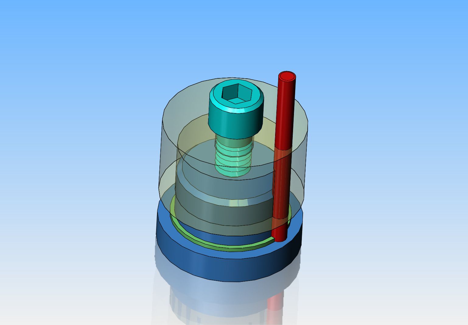
When the ring is cracked and sprung open it will be held in a way that the pressure will be evenly distributed around it.

Imagine if you spring open a ring and stick a piece of flat bar in the gap. Almost all the stress will be transferred to the point across from the gap. During the stress relieving process a flat spot will be created directly across from the gap and when sprung closed, that spot will not touch the cylinder wall.

The fixture will hold the rings as best to avoid the deformation of the ring so when sprung closed, it will return to being round again at the correct diameter.

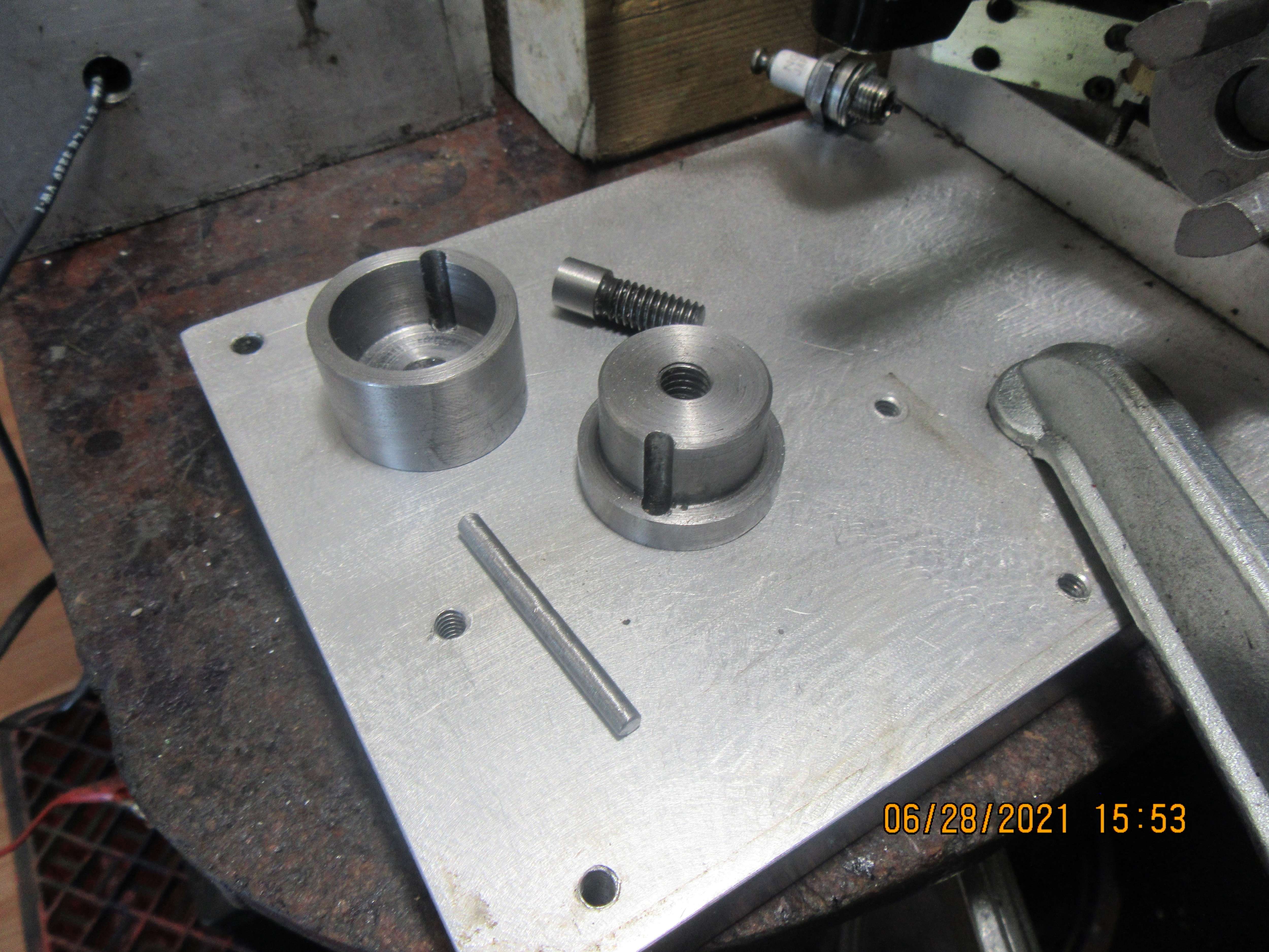
That's the best I can describe it. Once you build the fixture and get your rings in it tighten it up and heat. I have never had 100 percent good ones so if you need 2 do 5. 2 you need, 2 spares and the last one in case of a bad one.
 
using Steves figures I get it to look something like this.

I have clicked on the inner edge of the ring highlighted with the blue line and that is showing a measurement of 2.923"

Pi x inner ring diameter = 3.142 x 0.930 = 0.922"

Thats close enough to the same circumference for me.
 

Attachments

  • trimble2.JPG
    trimble2.JPG
    68.8 KB · Views: 130
Brian,
You appear to have drawn the ring as some sort of oval. The expanded ring will be a circle whose diameter will be the circumference of 1.006" plus the distance across the dowel (diameter).

Mike
 
Okay, I've redone the two dimensions for the offset and the mandrel diameter, and redrawn the ring as being circular, tangent to the left side of the mandrel and up against the two sides of the red spacer rod. I think I'm getting pretty close to what Trimble intended. I can go ahead and make the fixtures based on that. When I split my rings (which I haven't made yet), I will have to see if they fit the way this model shows them. If I have to, I can always monkey about with the mandrel diameter after the fact. Thank you Jason and Steve.---Brian
v6Is0Z.jpg
 
This dialog is very interesting. It also shows why drawings in larger companies often have "drawn By", Designed by", and "approved by".
We (hobbiests) are lucky to have the internet and friends to help check our designs.
 
This dialog is very interesting. It also shows why drawings in larger companies often have "drawn By", Designed by", and "approved by".
We (hobbiests) are lucky to have the internet and friends to help check our designs.
I have tried to understand the Trimble method and I understand some of what he is doing but I have never been able to figure out where he comes up with some of his numbers. I can plug in the values and come up with the numbers but I have never been able to figure out where he comes up with something like 1.0072 + .1569 etc.

You are correct that it is very helpful to have a group like this where we can ask a question and receive input from like minded individuals. For instance last week I asked if there was a way to make custom decals for out engines and I received several answers within a very short time. Frequently it is not even the answer but the information on where to obtain the information.
 
I'm not quite sure where he gets those numbers from either.

The spread ring won't be a true circle, as Steve said there is a bit more bending going on opposite the split and gradually decreasing to nothing at the split but hard to draw and certainly not the shape Brian had in his earlier image (mine is not actually completely right either).
 
I tweaked my drawing a bit more to have the variable change in radius that Trimble gives where it is more opposite the split than at the split using the internal radius as the one to change but should possibly be along teh neutral axis and eyeballed the 30degree increments so not perfect but good enough for this example.

First sketch shows the dimensions taking radius increase from his chart.

Second is the actual ring from that shape laid onto the fixture. Few gaps are my imperfect sketch.
 

Attachments

  • trimble3.JPG
    trimble3.JPG
    53.4 KB · Views: 129
  • trimble4.JPG
    trimble4.JPG
    46 KB · Views: 134
The sheet is a little thing I wrote based on the Trimble math. Here it is with the .038 X .038 rings. Notice how that simple changed made for a completely different fixture as for as mandrel diameter and dowel offset. If you are wondering about any further changes I have attached the little ring utility.

Type in the cylinder bore and the utility will give the Trimble numbers for width and thickness. The actual width and thickness can be changed and I do it often. I have a .027 parting tool so I would retain the thickness at .043 but change the width to .0255 mostly because it's easier to groove the pistons and of course I'm lazy. When you enter in what the "real"/ actual thickness and width the rind is going to be, the correct numbers for the fixture and ring groove are calculated. If you go back and edit the actual numbers the dimensions for the fixture are updated automatically. I don't remember but I think I put this in the downloadable files section years ago but I could be wrong.

View attachment 126824
Hi do you know of a ring math calculator for mac
 
The sheet is a little thing I wrote based on the Trimble math. Here it is with the .038 X .038 rings. Notice how that simple changed made for a completely different fixture as for as mandrel diameter and dowel offset. If you are wondering about any further changes I have attached the little ring utility.

Type in the cylinder bore and the utility will give the Trimble numbers for width and thickness. The actual width and thickness can be changed and I do it often. I have a .027 parting tool so I would retain the thickness at .043 but change the width to .0255 mostly because it's easier to groove the pistons and of course I'm lazy. When you enter in what the "real"/ actual thickness and width the rind is going to be, the correct numbers for the fixture and ring groove are calculated. If you go back and edit the actual numbers the dimensions for the fixture are updated automatically. I don't remember but I think I put this in the downloadable files section years ago but I could be wrong.

View attachment 126824
It is interesting that your calculator gives a different result than what I come up with using my spreadsheet calculator. I entered a 1.25 dia ring and my spreadsheet and I come up with M=1.1804 and Offset = .6232. Your calculator gives M = 1.1607 O = .625.

Petertha also shows his spreadsheet in
piston-rings-trimble.32899/
and his calculations and formulas are the same as mine.

I am not saying that your calculator is wrong. I may have done something wrong. I would be happy to send you my spreadsheet if you are interested. Lots of different opinions here.

Gordon
 
Today I made the Trimble heat treat fixtures. I managed to hit the numbers "right on", so if my cleaved rings fit, the fixture and the rings go into my new heat treat oven for 3 hours at 1100 degrees F.
I decided at the last minute to make the fixtures from mild steel instead of cast iron, but I don't think it will make any difference. Why is the head turned on that 5/16" cap screw?---I really don't know, but that is the only 5/16" cap screw that I could find around here.
KLOII0.jpg
 
I cant check my stuff. I was forced into a windows 10 computer when the old one quit. It wont let me install my Visual Basic 6.0. Says it wont run.
Steve, just set up another computer as a stand alone( not connected to the web) and load the older windows system, I have one set up with XP to run my old film scanning progs and I also run Autocad 14 on it.
Cheers
Andrew
 
1624915842436.png

Steve you should be able to run it just click on it and go to properties and set it to run with xp capabilities I know that worked for me in windows 7 for a program I used. I would think 10 would still have that option.
 

Latest posts

Back
Top