A new attempt at making piston rings

Home Model Engine Machinist Forum

Help Support Home Model Engine Machinist Forum:

This site may earn a commission from merchant affiliate links, including eBay, Amazon, and others.
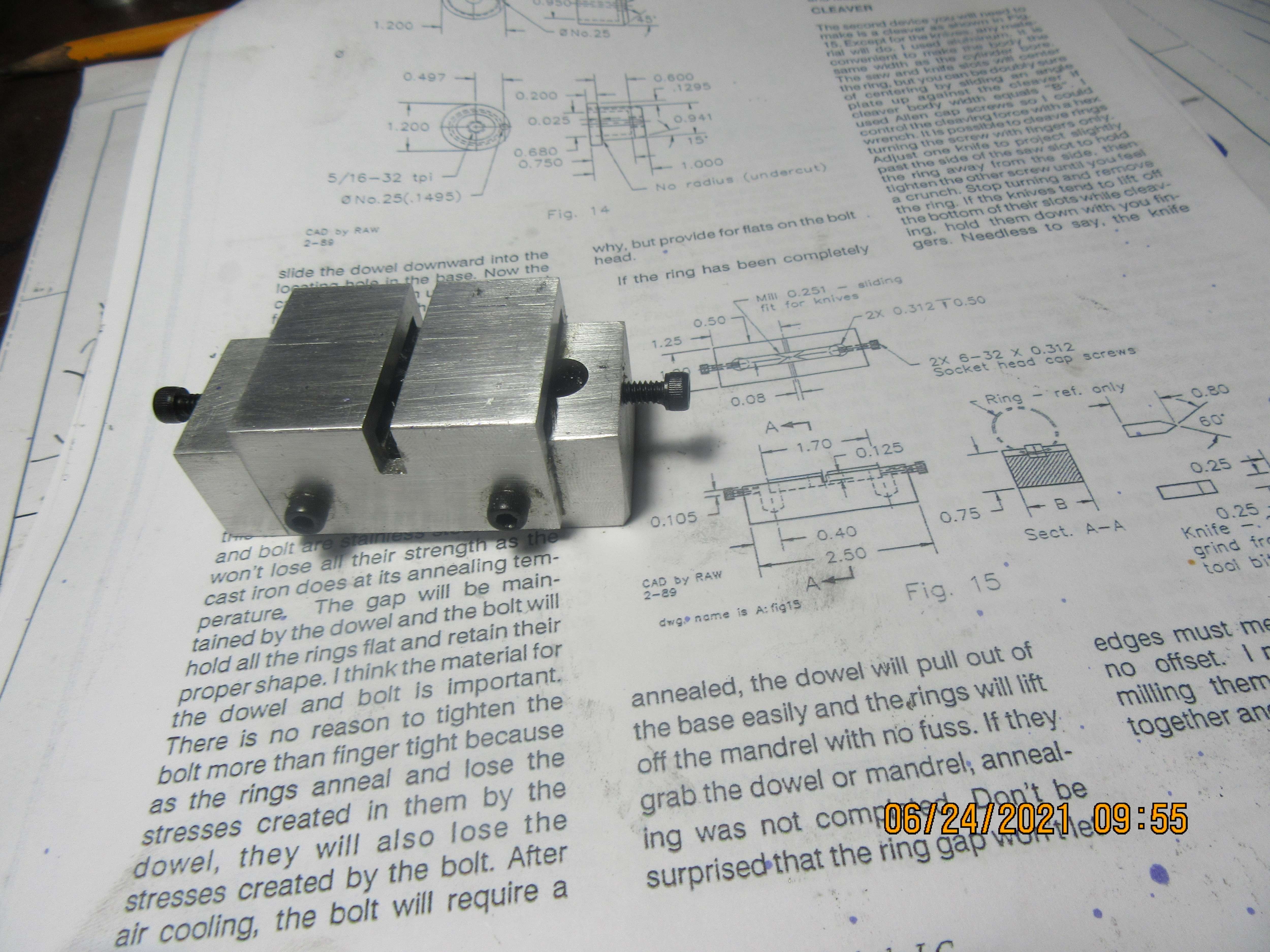
Okay, next step is to add the "Rupnow hold down" to the "Trimble cleaver".
67drwp.jpg
 
Dear Brian,
I was following topic for a while and few some suggestions about design.
I think you can split the holding profile in the middle and place a slot on A point. So you can adjust it to your thickness. While supporting from B screw you can press from C to split.
Just an idea.
1624537865263.png

Yavuz
 
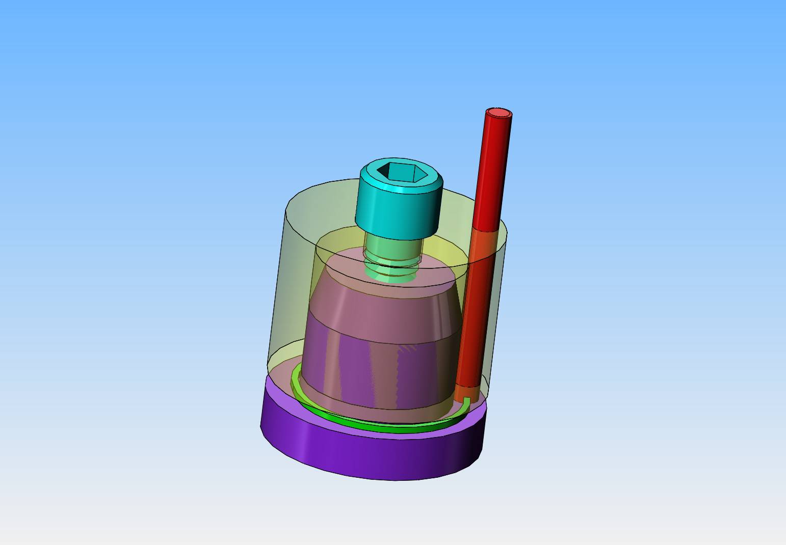
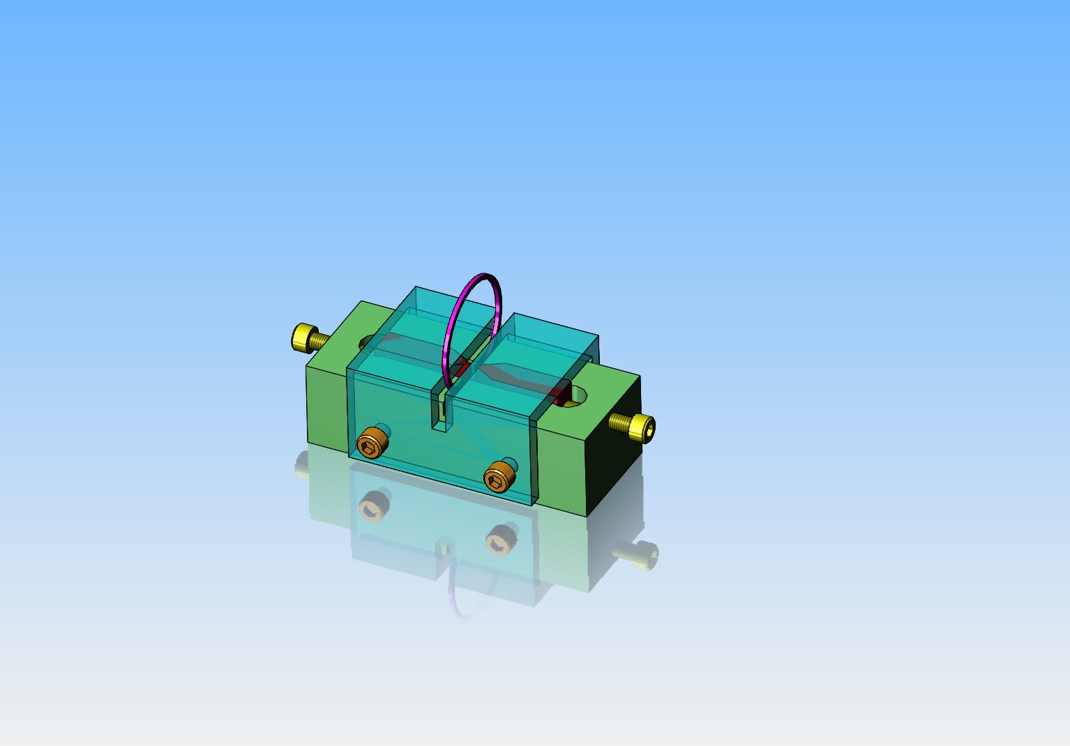
So, here we have a Trimble ring cleaver, with a Rupnow add-on. The "add on" keeps the cleaver knives from trying to kick upward out of the guide slots when the screws are tightened. In a perfect world, I would have had a ring to "pose" in the picture, but I'm out of rings now until I make some more. I did "cleave" one piece of a ring, just to assure myself that this thing works, and it does (I don't see any difference from the rings that I broke in the vice with my fingers).
iLa4VD.jpg
 
Found something out today. Two weeks ago I ordered a "Fine India Stone" from Sharpening Supplies .com on the internet. Today I went searching for it because two weeks should get it from anywhere in the USA. I phoned Canada Post with the tracking number supplied by Sharpening Supplies. Canada Post informs me that the stone shipped out of Sweden a week ago. What???---Sweden?? Okay, maybe I've been had. Of course, Sharpening Supplies never indicated that the stone was coming from Sweden. It doesn't really matter, I don't have any urge to do much machining right now, but still----
 
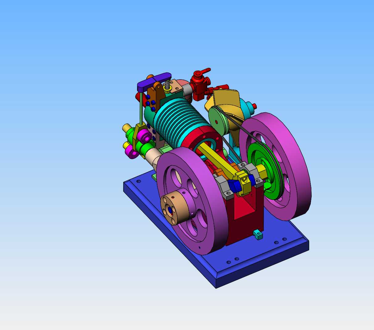
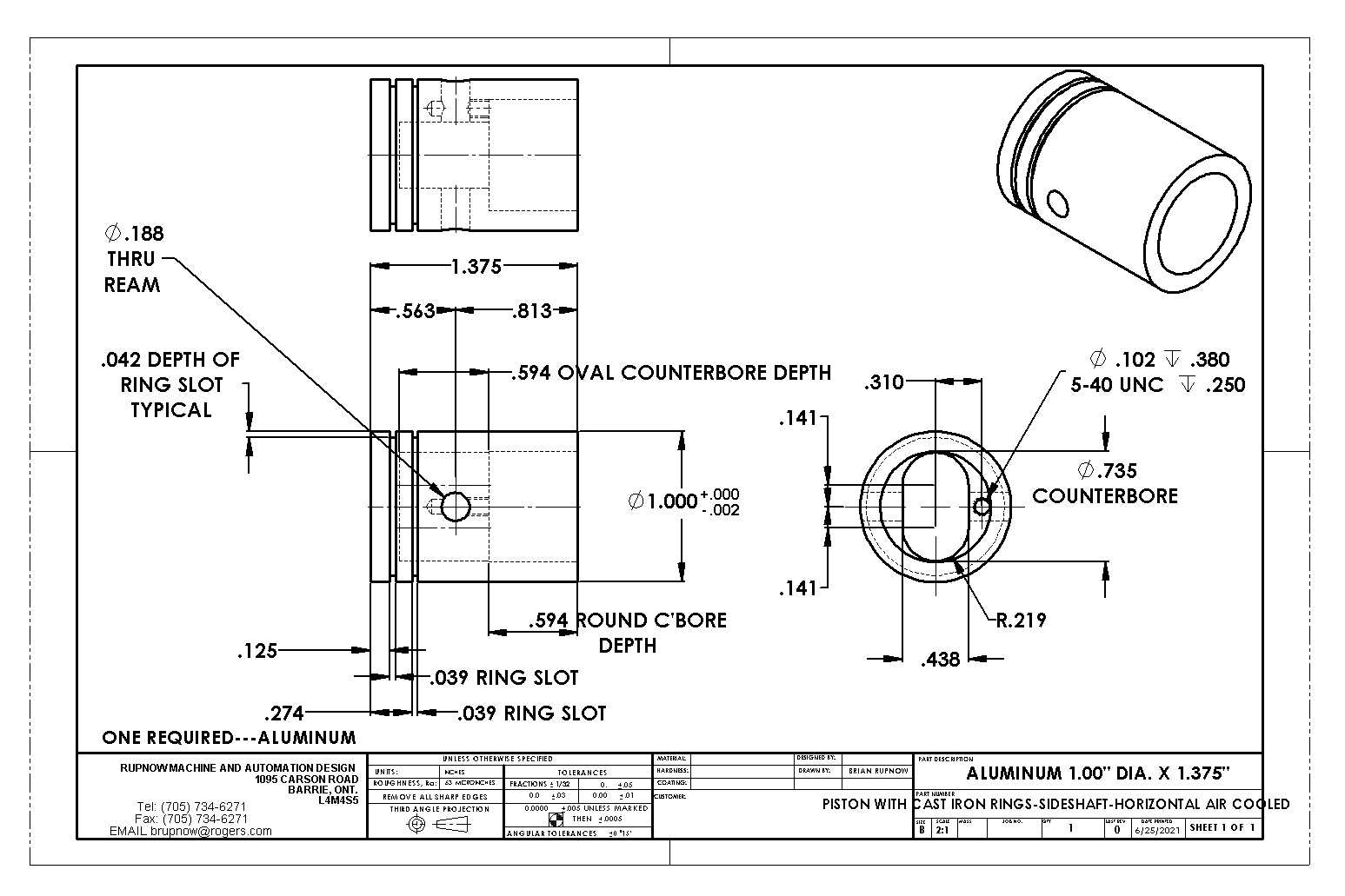
It's raining here today. I am fully vaccinated and bored, so I went out this morning and made a tour thru my tool shops. Came home and had a sleep.--And now it's time to move a little farther along with my pursuit of making cast iron rings. This time I wanted to modify the piston on an engine which needs no (or very little) disassembly to access the piston. I've decided that my air cooled side-shaft engine is a prime candidate. It runs very well, and by simply removing the two con rod bolts I can pull the con rod and piston out of the engine without doing anything else. The new piston will be aluminum instead of cast iron (mainly because aluminum is cheaper and I have some here). The new piston will be nominally 0.002" less in diameter than the bore of the cylinder. The rings will be 1 mm (0.039") x 1 mm (0.039") in cross section. The rings will be made following the Trimble method as much as I am able to.
CmWNGm.jpg

NIZx3X.jpg
 
If you make the rings.039 thick you not following the Trimble method. He says thickness should be .043 to .045 x bore. .039 makes wall pressure below 30PSI which he says is too low.
 
This is a video made today showing the side-valve engine running. I had to mess around with fuel tanks, but other than that the engine runs very well. Next step will be to make the new piston and rings and install them on the engine without changing any of the engine settings.
 
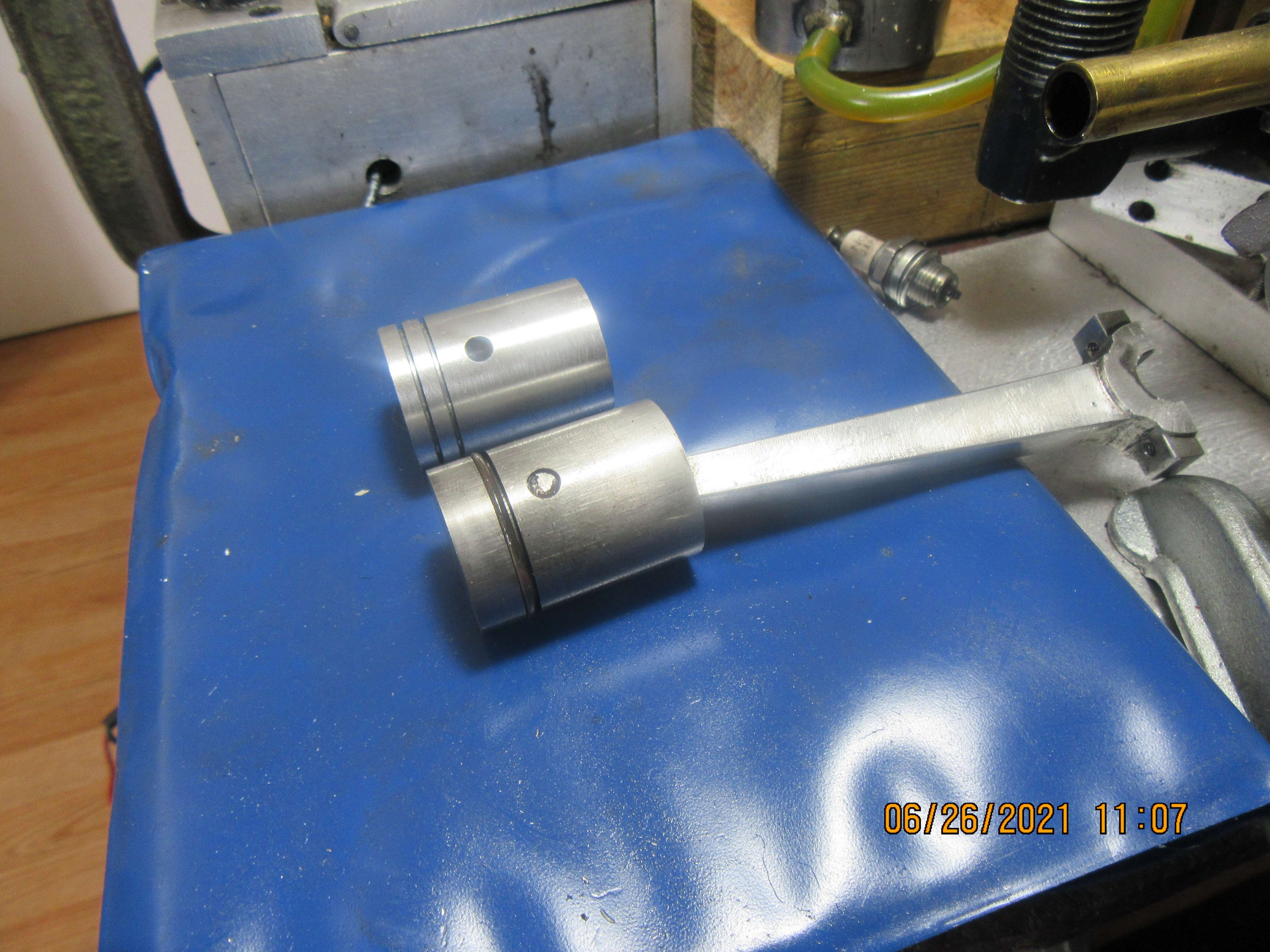
This mornings work was to machine a new piston with grooves for cast iron rings, setting alongside the old cast iron piston with a Viton ring. The old piston was 1.006" diameter and was almost an air-tight fit in the cylinder. The new piston is 1.005" diameter. Now I wait until my "fine India stone" arrives from Sweden so I can make the rings.
3FKage.jpg
 
FWIW I've bought a few stones over the years for model engineering purposes. I think India stone is shorthand for aluminum oxide and fine is ?? whatever grit meets your definition. Some I grudgingly bought as singles through the machinery supply places like KBC or Travers due to price. Others from typical sharpening suppliers maybe like you went through. More recently I've been pleasantly surprised at what I've received through AliExpress/Ebay which all come from Asia. It would not surprise me if its the classic middleman / markup game. Equally important is some means to lap them back to flat because they obviously wear with use. Which is yet another stone. Tom Lipton, Rob Renzetti & Stefan Gotteswinter have some good video content on this subject. Anyways good luck on the next ring making chapter. I hope this saves you some money you can invest in a dial bore gauge one day.
 

Attachments

  • SNAG-2021-06-26 002.jpg
    SNAG-2021-06-26 002.jpg
    240.4 KB · Views: 135
Tomorrow, if it's still raining I will make the Trimble heat treat fixture. It will be made of the same material as the ring itself, so I don't get into problems with differential expansion factors during heat treat. I only show one ring on there, however it will accept up to six rings at once. The round red rod is the "spreader", and if the heat treat is done correctly the red rod should pull out of the fixture very easily. If the rings are still "gripping" the red rod, then the heat treat hasn't done it's job.
95w9d3.jpg
 
Hopefully you will see this before cutting metal

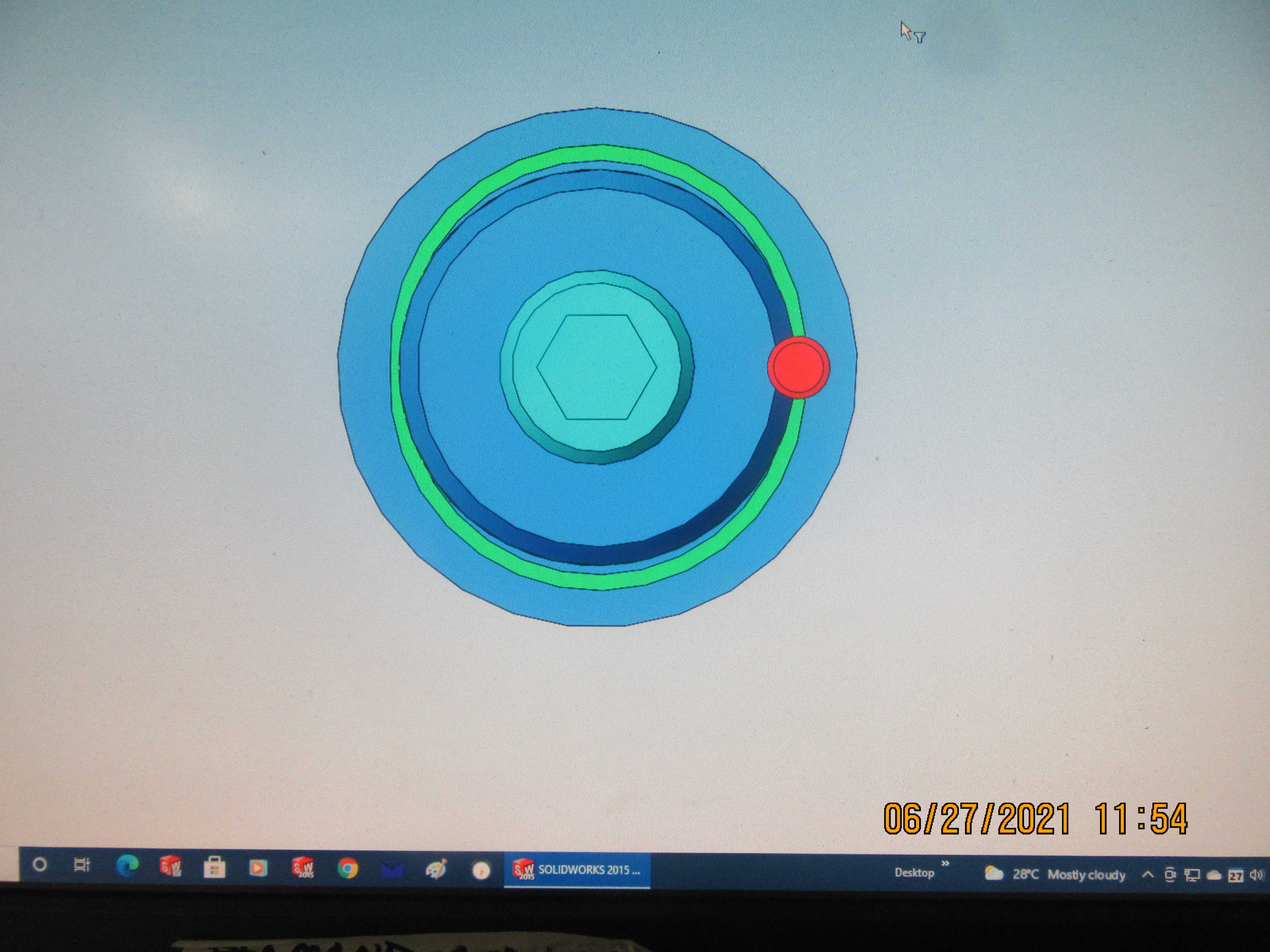
That does not look right to me Brian, the spacer rod usually ends up needing to be partly cut into the side of the spigot that the rings fir round. Also the rings are a closer fit on the spigot. If you look closely at Trimble's article you will see that at 0.497 from the ctr his 0.150" dia pin hole will need clearance on the 0.941" spigot. As you have it the rings can move about while tightening the top cap which will affect the gap.


What were the figures you used to arrive at those sizes in your drawing?
 

Attachments

  • trimble.JPG
    trimble.JPG
    46.5 KB · Views: 119
Last edited:
Hello Brian!

I am going to assume from your post that your bore is 1.006.

Trimble says your ring should be .043 X .0225.

From your drawing i assumed your groove is already cut to .039 wide so I made actual width of the ring .0375 for a .039 wide groove.

Dowel diameter should be .151. I would use a #24 hardened drill blank at .152

Mandrel diameter should be .950-.951

Dowel should be drilled in at .502 off center.

I agree with JasonB that something in your model looks incorrect. The dowel pin is typically embedded into the mandrel suggesting that in the model, the pin is drilled too far off centerline or the diameter of the mandrel is too small in diameter.

Untitled.jpg


DSCN1423s.JPG
 
I was all prepared to begin machining the heat treat fixture this morning, but it appears that I am lost in space. My cylinder bore is 1.006". My rings are going to be .038" x 0.038" (square cross section). The grooves in my piston are 0.039" wide x 0.042" deep. I had decided to make that red spreader rod 0.150" diameter, but since I haven't made the heat treat fixture yet, I can use a 0.152" diameter. Steve--I don't know where you got that chart from, but I don't have it. Can you please plug my figures into the chart and see what you come up with.---Brian
 
When the rings are on the fixture should they be a tight fit of the ring id to the fixture od? I may have done something wrong but I have always had a slight gap between the ring and the fixture. I have placed this gap opposite the ring groove. I seem to remember Trimble saying that was normal but I cannot find that now.

Gordon
 
Couple of thou clearance. See text just before and after fig 10 in SIC #7
 
The sheet is a little thing I wrote based on the Trimble math. Here it is with the .038 X .038 rings. Notice how that simple changed made for a completely different fixture as for as mandrel diameter and dowel offset. If you are wondering about any further changes I have attached the little ring utility.

Type in the cylinder bore and the utility will give the Trimble numbers for width and thickness. The actual width and thickness can be changed and I do it often. I have a .027 parting tool so I would retain the thickness at .043 but change the width to .0255 mostly because it's easier to groove the pistons and of course I'm lazy. When you enter in what the "real"/ actual thickness and width the rind is going to be, the correct numbers for the fixture and ring groove are calculated. If you go back and edit the actual numbers the dimensions for the fixture are updated automatically. I don't remember but I think I put this in the downloadable files section years ago but I could be wrong.

Untitled.jpg
 

Attachments

  • RingMath.zip
    5.2 KB · Views: 97
Last edited:
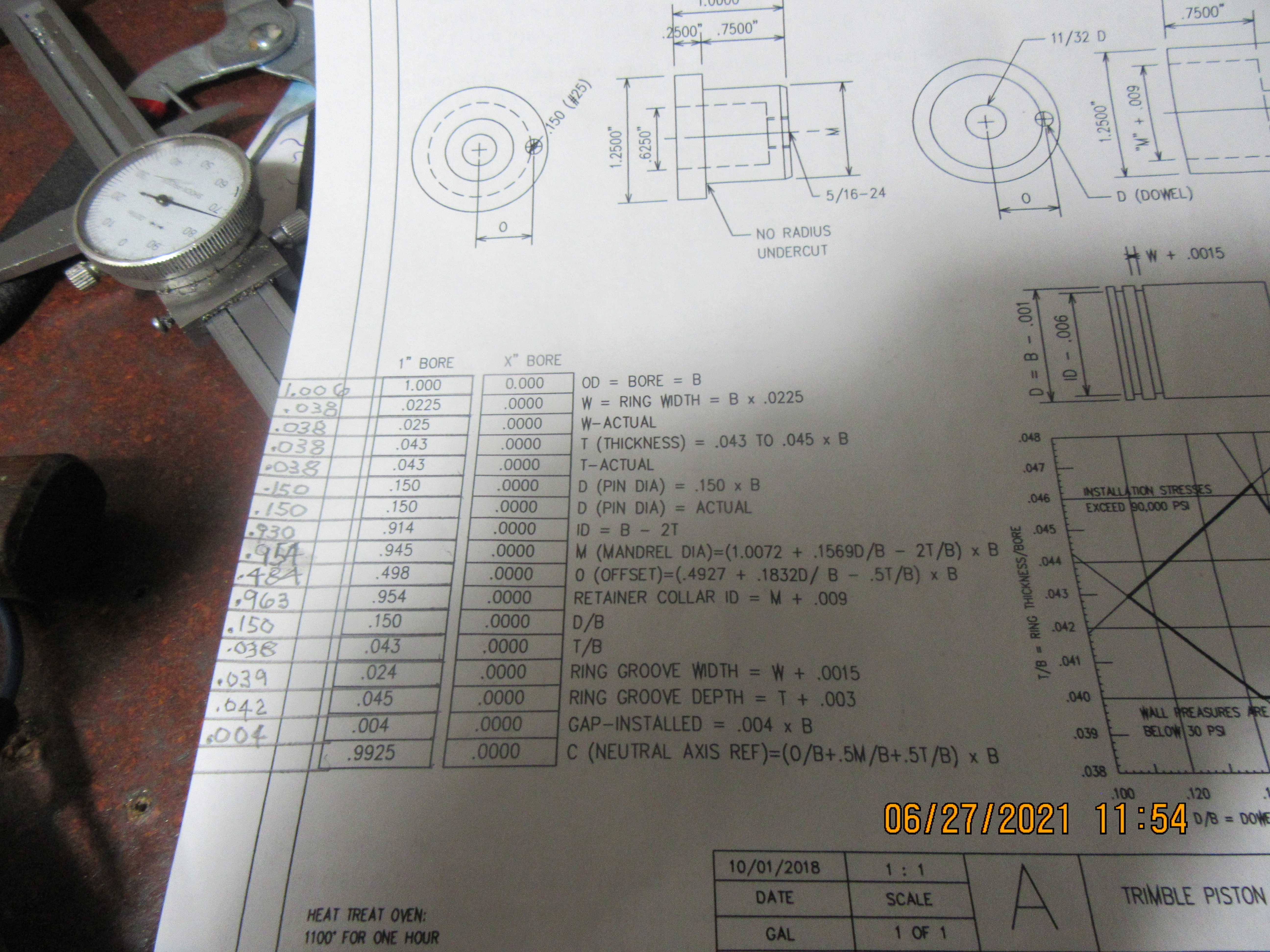
I have put in the figures for my application on the left hand side of the columns in pencil, but the resulting mandrel and offset dimensions I arrive at don't look right to me. The ring isn't going to fit down properly on the mandrel using the numbers I have arrived at. My given features that can't be changed are a ring of 1.006" outside diameter x 0.038" square cross section. Can somebody please take a look at this and see where I've gone wrong.----Brian
nUcbxV.jpg

Xy3avq.jpg
 
Last edited:
Dowel offset in pencil is wrong, you have .484 and Steve has it at .504

So is the mandrel dia, you have it as .954, Steve .960
 

Latest posts

Back
Top