A multi-cylinder crankshaft machining tutorial

Home Model Engine Machinist Forum

Help Support Home Model Engine Machinist Forum:

This site may earn a commission from merchant affiliate links, including eBay, Amazon, and others.

gbritnell

Project of the Month Winner!!!
Project of the Month Winner
Joined
Jul 16, 2007
Messages
2,981
Reaction score
1,047
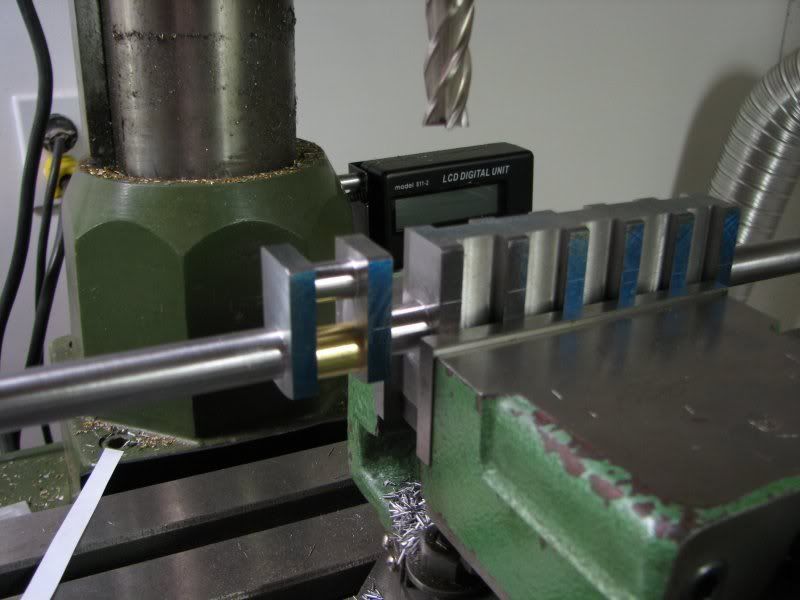
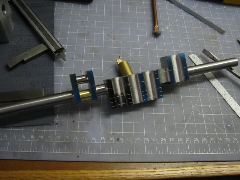
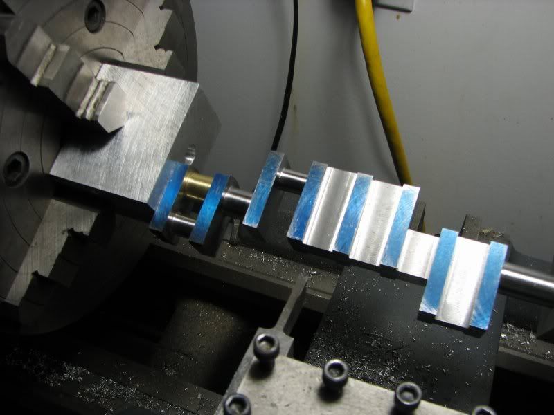
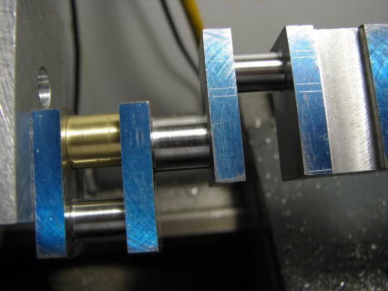
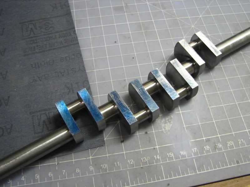
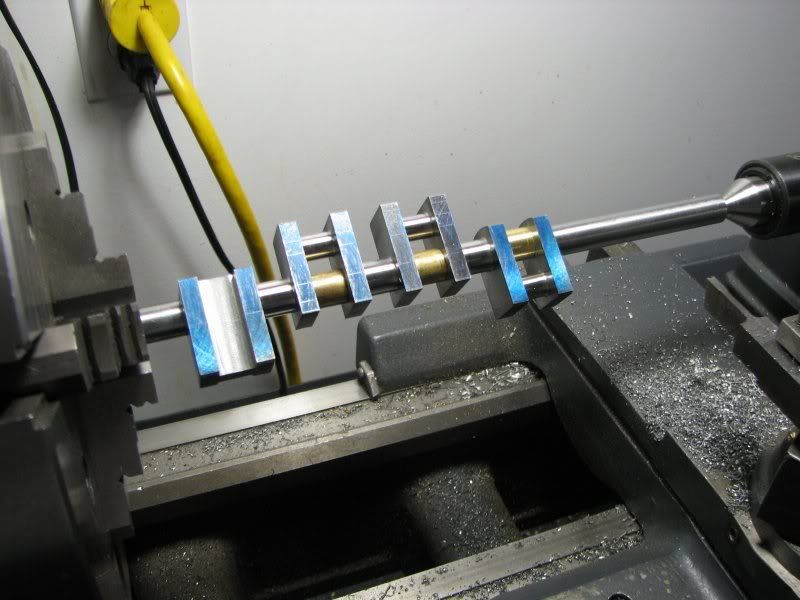
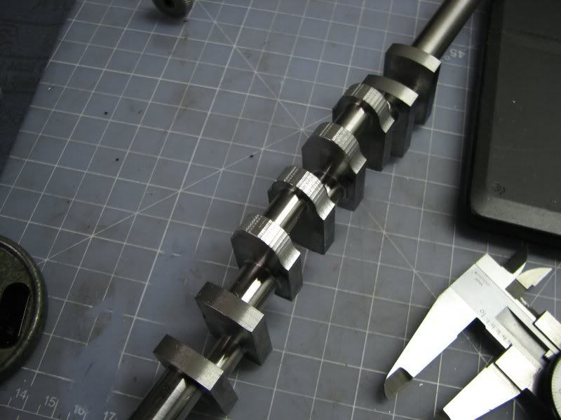
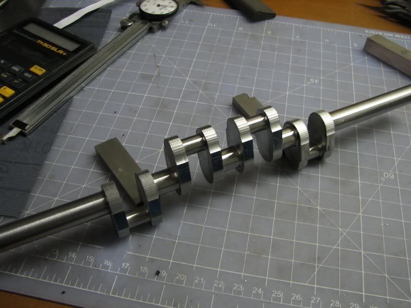
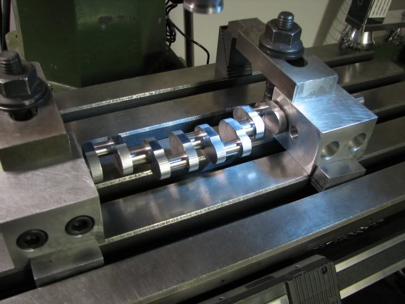
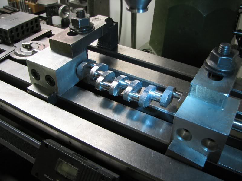
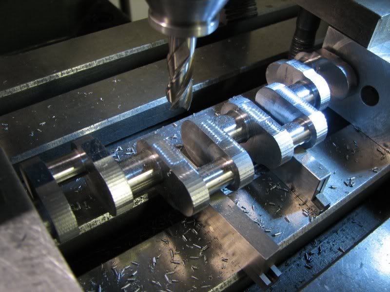
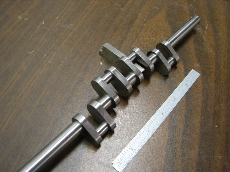
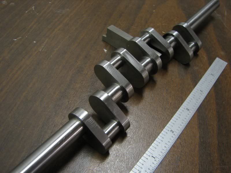
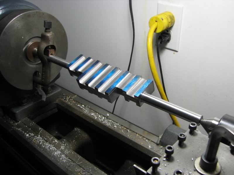
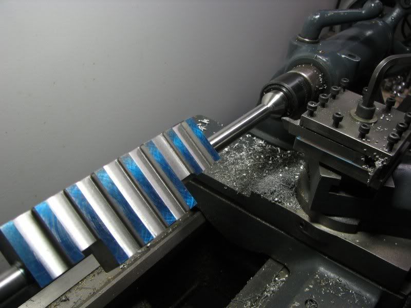
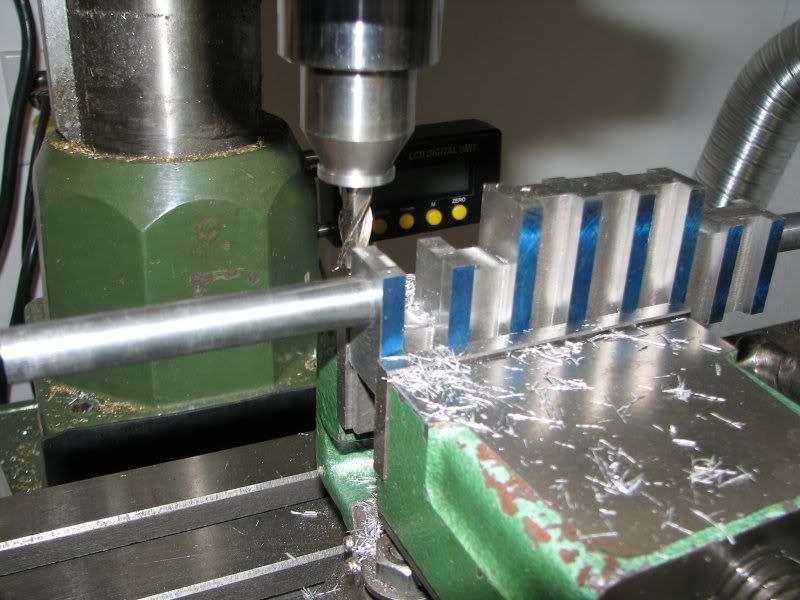
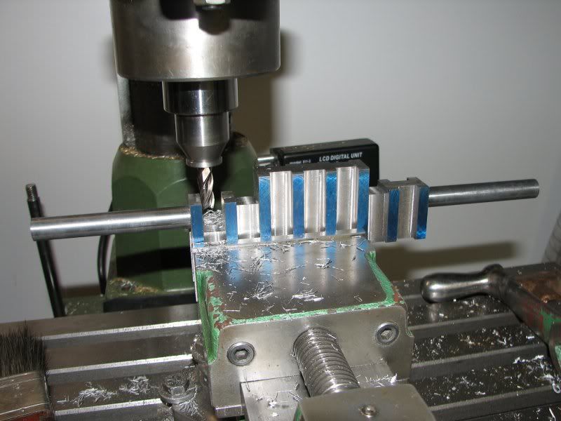
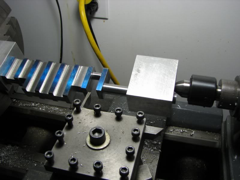
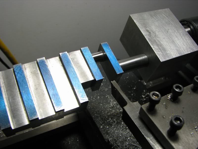
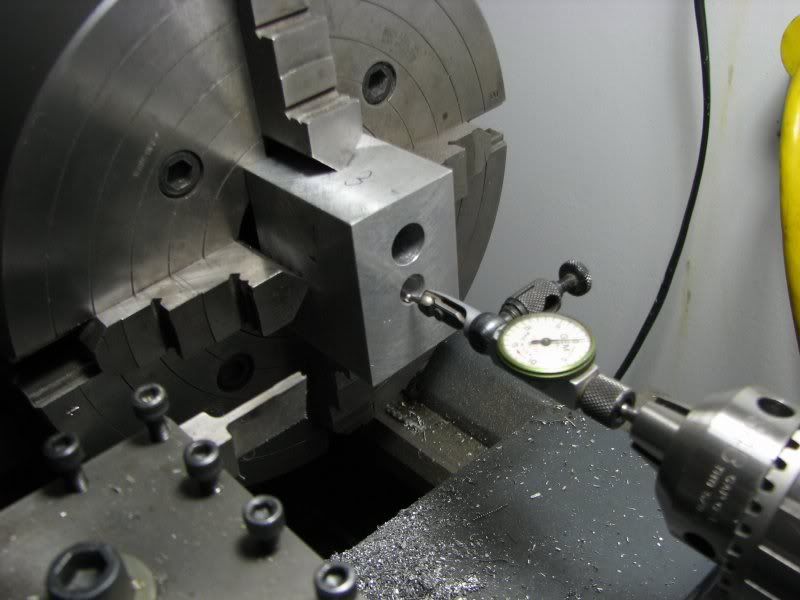
Gentlemen, the following will be a tutorial on machining a multi-cylinder crankshaft. In this case it's the crankshaft for my Holt tractor engine. I feel when making this type of crankshaft the most important factor is the machineablility of the steel. Although everyone has their favorite material, partly based on the equipment you have available, I now use 1144. I have made cranks from 1018, 12L14 and cast iron. I guess if a person had the right equipment 4140 would make a nice part. 1018 steel which is a common CRS is available as a flat rolled stock which expedites machining because you don't have to take a piece of round bar and machine it down to a rectangular shape. The problem with this material is that with cold rolling it builds up internal stress and when machined it likes to warp. Sometimes when you get the bulk of the material chopped off it stablilizes to some degree. 1144, commonly refered to as 'stressproof' is great stuff to work with. It has a higher machineability rating than 1018 ( 83% vs. 78%) and one of it's most endearing features is that it doesn't warp, or at least it's negligible. The bad thing is they don't make flat stock so you have to cut a piece of round down if that's your starting point. Most everyone here knows the virtues of 12L14 (leaded free machining steel) with a machineablility rating of 193%. I have made a couple of cranks from this steel with no adverse affects. The tensile strength ranges from 78,000 for 12L14 to 115,00 for 1144. What that all means to us as modelers I can't say. Our cranks are generally small and don't have great torsional loads put on them so the tensile strength is probably not as important as how well you can machine it. I don't know of anyone who has run their engine for a long period of time and then torn the engine down to check and see if the crank throws are still in the proper radial postion as when it was machined. That's not saying that nobody has, I just haven't heard anyone say they have. OK, enough with all this and on to the build. I started out by making a piece of rectangular stock to suit my requirements. I layed out the shapes on the stock and then started cutting. I first chuck the stock up close in my 4 jaw chuck, indicating it close and center drilling each end. After this I extend the stock far enough to cut one mainshaft. I leave a little material on it for the final setup. I then turn it around and do the other end. After this I mount the stock between centers and finish the main journals to size. I might add at this point that the procedures I use for this crank could be somewhat different depending on what size crank you're making and how ridgid it is. The first couple of pictures show the machining of the mains. I didn't take pictures of the center drilling as my explanation should suffice.
IMG_2875.jpg

IMG_2882.jpg


After the mains are finished I take the crank over to the mill and cut the material out of the first web. I only do one at a time to keep as much strength in the stock as possible.
IMG_2884.jpg

IMG_2885.jpg


Now it's back to the lathe to turn the first throw journal. I use high speed tooling on my cranks. That's not to say that carbide can't be used, I just like high speed for this type of work. I can put a much sharper edge on it and hone it if it gets a little dull. The tool I use for the throws is like and extended cutoff tool made long enough to get to the bottom of my cut. It has clearance on both sides so I don't scuff the sides of the throws. The width is already finished on the mill. I only need to make it round and to size. When you start out the cut will be intermittent but not as bad as trying to cut all of the stock out on the lathe. The nose shape is what's refered to as 'bifurcated'. It has a notch gound into it so that you're only cutting with the 2 small outboard edges. The total width of the nose is a little less than 1/2 the width of the throw. This allows you to move the tool back and forth to clean up the whole journal. There is also a small radius on the corner. This gives the crank strength at the junction point. When first setting up the tool mount your dial indicator somewhere and indicate across the 2 points on the tool. This is very important to get a parallel cut on the journal.
IMG_2886.jpg

IMG_2892.jpg

IMG_2913.jpg


I'm going to interject this step to clarify the mounting of the shaft for turning the throws. As you can see by the pictures I have made up 2 blocks, one for the chuck end and one for the tailstock end. These blocks need to be dimensionally the same as they will be used not just for clamping but setup. The tailstock end has one finished hole, reamed or bored, and one center drilled hole. I try to make the center drilled hole as large as possible for as much support as I can get. For cranks like the ones on the Stuart engines I split the block and put a cross threaded hole in it to clamp onto the crank. On these blocks I drilled and tapped from the side parallel to the through hole but on the side oppostite the center drilled hole. This will be for clamping the shaft into the block. The chuck side block has 2 finished holes in it, one the diameter of the shaft and the other whatever you choose. It just needs to be in line and smooth for indicating. This block also has 2 tapped holes in the bottom for clamping. These were 3/8-16 holes. I also make up a brass shoe with the radius of my shaft on one end to clamp against the shaft. Once my block is clamped into the 4 jaw chuck and indicated it stays there. When I have to cut the inside mains I remove the chuck with the block in it and replace it with my collet chuck. This keeps the accuracy of my setup for the subsequent throws. You might say that this takes quite a bit of time, changing chucks and all, but if you removed the block and had to reindicate it every time it would take just as long or longer. I am fortunate enough to have several chucking devices available.
IMG_2938.jpg

IMG_2941.jpg


Gbritnell, once again, EXCELLENT - Thank you :bow: .
Edit: Can I ask: in your 2n'd last post - photo 2 - How did you fasten the main shaft in the "block" you use for turning off-center ? - Thanks- you answered it in the third post :)
Sincerely, Arnold
 
You will notice in these steps that I cut the first throw up against the tailstock end and then switch to the chuck end. The reason for this is I try to cut as close to the support block as possible. The next thing you might ask is "why don't you slide the shaft all the way into the tailstock block?" I can't, it hits the live center. I don't have one of those long skinny center attachments. After the first throw is cut the crank goes back to the mill to rough out the next main. This process is repeated all the way down the crank. I made up some snug fitting brass blocks and super glued them into the finished throws. This provides longitudal support when the live center is pushed into the tailstock block.
IMG_2896.jpg

IMG_2899.jpg

IMG_2902.jpg

IMG_2917.jpg


I slowly work my way down the crank, one main, one throw, one main, one throw, until I get finished. WARNING!!! Always make sure your tool is clear before starting the lathe. Turn it over by hand at least 2 revolutions to check everything, then start. Another thing I forgot to mention. You know very early on I said the clamping blocks needed to be dimensionally the same, here's why. When you clamp the crank into the chuck block it first needs to be parallel to that block. For that I use a small dial indicator mounted in a block. I slide it along the clamping block and rotate the crank till it's parallel, then clamp. Now I slide the the tailstock block on and snug up the clamping screw just enough so I can still turn the crank. I Then take a steel parallel 1/2x3/4 (factory made) and clamp it against the sides of both blocks with small machinists clamps, then tighten the clamp screw and remove the parallel. The worst that can happen is the throws might be a minute amount out of parallel on the axis. For model work I don't think you'll ever notice it. We now have a finished crank, at least to this point.
IMG_2946.jpg


I should have thrown in this picture with the last one but it's hard keeping all this stuff straight without a script. LOL
IMG_2931.jpg
 
This crank has radiused edges on the throws and mains. Not just a radius concentric with each. I therefore had to cut them afterwards. The method I used was to make a layout in AutoCad of what I needed and then sined and cosined (stepped) the radii off with a ball mill. I might also say that they are two different sized radii so two separate step off charts were needed.
IMG_2950.jpg

IMG_2965.jpg

 
Now I had to join the radii with a straight cut. I calculated how much I would need under the throw to get the required angle and set up an adjustable parallel. This is where you start getting butterflies. I sure hope something doesn't come loose!! It would only take me seven hours to get back to this point. You'll see I used the clamping blocks from the lathe to hold the crank secure while doing this. In this view you can see the tapped holes in the bottom for the set screws.
IMG_2971.jpg

IMG_2973.jpg

IMG_2980.jpg


Now we're down to the final steps. I put layout blueing on the radius steps and got a nice sharp mill file and blended the cusps (high points). I also had to file the flats a little as I told you in my spark plug post my Enco doesn't make satin cuts. The tool marks are only about .00025 but enough to look crummy with a digital camera and to me also. That's it gentlemen, one Holt crank. I only had to cut the Woodruf key slots in the ends for the flywheels. As an aside I put the crank between centers on my lathe and ran an indicator on the main shafts. The center main was out .0015. When it's running I'm the only one that knows this. I wish it were .0000 but without grinding facilities this is as good as it gets. I have heard of a fellow that won't settle for anything less than perfect. If it's not right he throws it out and starts over. I lost that vanity quite awhile back. Have a good day and don't be afraid to try this.
George D. Britnell
 
Oops!! I got so carried away babbling that I forgot the last pictures.
IMG_2985.jpg

IMG_2989.jpg

 
George,
I enjoyed this tutorial. The machine operations are a bit beyond my current capabilities, but I like your philosophy... make something to your own satisfaction and specifications.

Cheers,
Phil
 
Excellent tutorial, George. I daresay, there's something here for the majority of us.
Thanks for sharing your good work!

Dean
 
I'm just soaking up all this experience and hoping I can remember it correctly when I find myself needing it.
Thanks GB. The hard work of making these long detailed posts and remembering to stop and take pictures during times of intense concentration. It is all very appreciated and we foolish dreamers, desiring to be creative, cannot thank you enough for the help it provides us.

Humbled and Inspired at the same time,
Kermit
 
Darn George,

Every time you post something it adds to my "wannado that!" ;D

Can you explain/demo how you grind the turning tool?
 
Thanks everyone for the comments. A member of this forum had contacted me offline and I explained that I have built so many things over the years, before digital cameras, and didn't have the resources we have now for photographing our work. Now when I work on something I have my camera in my shop and take shots of almost everything. The nice thing is if I don't like it I just delete it but it gives me a photographic record of almost everything I make. It takes time to put together a tutorial but I enjoy sharing them as much as much as I enjoy sharing my work. As far as grinding the tool for turning, if you look at the picture I posted you can see the shape of the tool. It is totally ground by hand. I start with a 3/8 high speed blank and grind the clearance notches in the sides. I then reduce the tip width to .04 less than half the width of my journal. This will allow me to move the tool back and forth across the face of th journal for a complete cleanup. I put a small radius on the outer corners. As far as the notch in the center, I grind that with a cutoff wheel in my Dremel grinder. The shape isn't important, a radius or a square notch will do. When done with this I stone a small radius on the inside corners. If you are cutting a tougher material you can also put a little bit of top relief on the cutter making the cutting edge a little sharper. The reason I don't show that on the cutter in the picture is because if you grind the top clearance a little crooked it's hard to get the tool indicated square to the lathe axis so on this tool I haven't done it. As I am plunging in I move the carriage left and right a small amount to keep the tool from chattering.
gbritnell
 
George, your "How To" threads are inspirational, in addition to being a dam good read and a massive help to folk with less experience, like me, please keep them coming they are just invaluable imho, thank you :bow:

CC
 
CrewCab said:
George, your "How To" threads are inspirational, in addition to being a dam good read and a massive help to folk with less experience, like me, please keep them coming they are just invaluable imho, thank you :bow:

CC

What he said. :bow: :bow:

Best Regards
Bob
 
CrewCab said:
George, your "How To" threads are inspirational, in addition to being a dam good read and a massive help to folk with less experience, like me, please keep them coming they are

CC


Same here. th_wav


Ron
 
Back
Top