Tony Bird
Senior Member
Hi,
Stage 1.
It started with a small steam weep from the water gauge on a Mamod SA1 steam car, which the repair of gradually got a bit OTT. Mamod water gauges had been repaired before but their model railway locomotives where it is fairly straightforward job. After removing the boiler from the locomotive the pop rivets which hold the gauge in place are drilled out. Brass screws are the put in the boiler from the inside and then soldered in place so replacing the rivets with screws, doing this allows any further mishaps with the gauge to be repaired without removing the boiler from the locomotive.
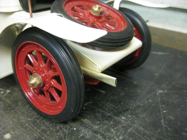
It was thought that it would be the same for the steam car as the gauge glass was also held in place with pop rivets. There was a major difference due to the difference in construct between the locomotive and the steam car the locomotive was screwed together but the car was totally held together with poprivets! Also it was necessary to almost take the whole car apart to access the boiler. So it was decided that after drilling out the rivets all of them would be replaced with screws. Other jobs that were done during the disassembly the cast wheels were eccentric so they were centred and bushed and their knock on retainers replaced with blind bushes held inplace with grub screws. Some of the rivets were in places where it was not possible to fit a loose nut so shouldered nuts were made and soldered in place. With this work done it was now possible to take apart and assemble the whole car easily. Another bit of a problem was that the steam pipe was soldered to both to the engine and boiler, which made them difficult to handle so the were unsoldered with the intention of using a union to connect them together again.
Now the part that caused all this work was repaired the boilers water gauge. It was found that the boiler had been silver soldered together unlike the previous Mamodboilers worked on which had been soft soldered. This allowed the pop rivet replacing screws also to be silver soldered and it was decided to fit a bush in the back head of the boiler for a banjo fitting connected by a pipe to a Goodall water top up valve. Most Mamod water gauges fail because the boiler has been allowed to run dry, fitting a Goodall valve makes it a lot easier to maintain a safe water level in the boiler. The boiler had been difficult to remove from its frame so the frame was split into two pieces which were then held together by some aluminium angle. The safety valvepressure was increased from about 15 psi to 25 psi.
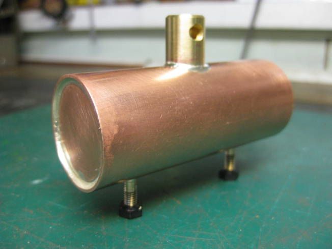
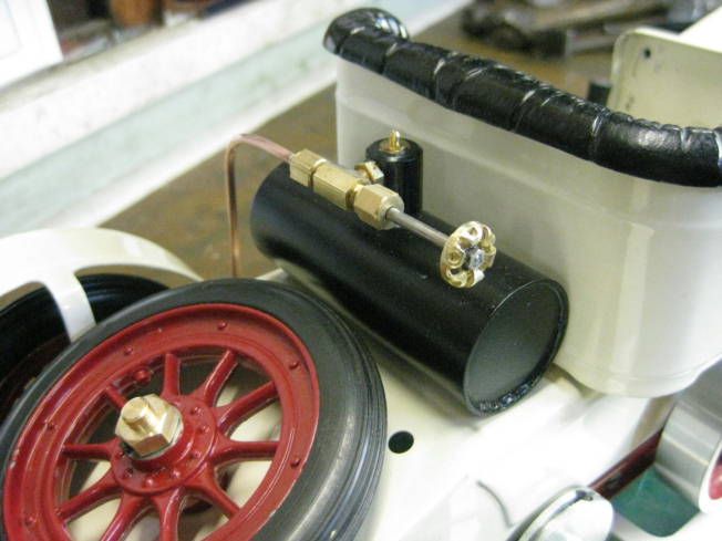
As the boiler had been found to be silver soldered together it would stand extra heat so it was decided to replace the solid fuel tray with a ceramic gas burner, the gas tank being made to look like a petrol tank mounted behind the driving seat.
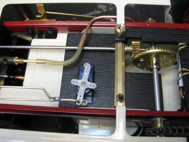
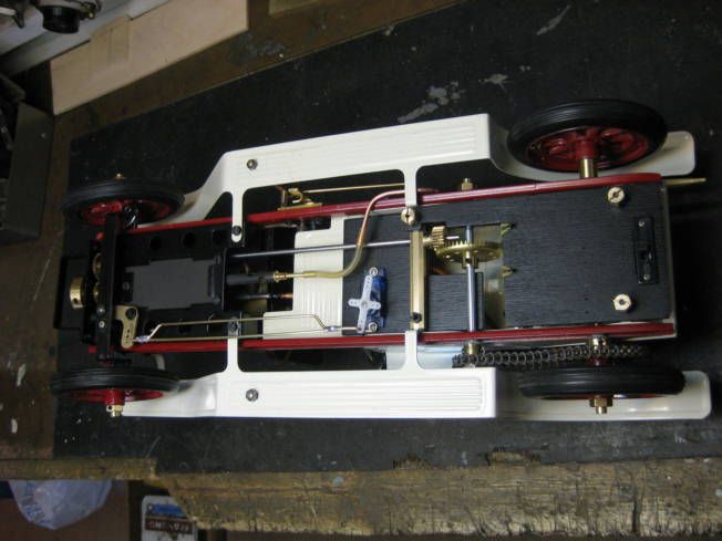
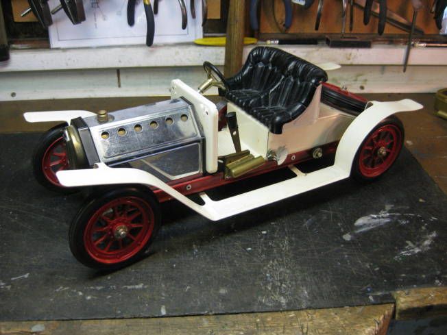
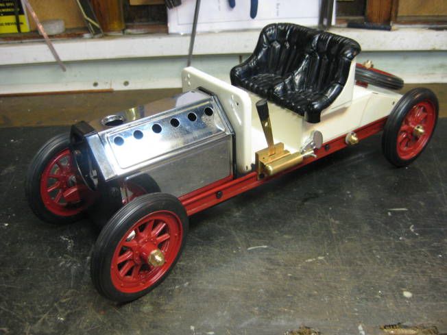
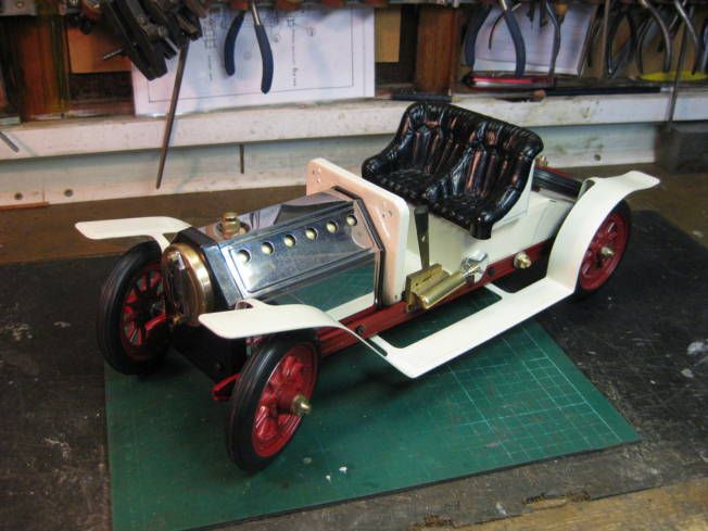
A certain amount of work was done on the engine fits, finishing the port block, enlarging steam ports and turning oil rings on the piston. It was thought that it would be fun to fit R/C to the steering so an actuating pin was fitted to the steering tie bar. The car was now assembled and without mudguards it looked a little like an Itala with the mudguards fitted it was something like a Stutz Bearcat. As the filler valve was to be fitted to the running board it went down the Stutz route.
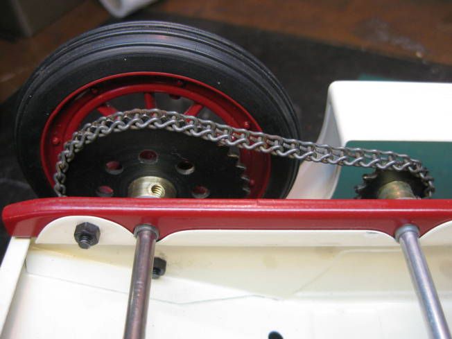
The assembled car was now tested on the workshop floor and with a gas burner and with a higher boiler pressure it put in a credibleperformance. As designed it has a singleacting oscillating engine with a 5/16 bore and a ¾ stroke geared 10:1 to one of the rear wheels. The boiler produced more than enough steam for the engine, so thoughts were made about fitting adouble acting engine and going GT!
Stage 2 to follow.
Hopefully the following photographs will give an idea of the alterations.
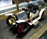
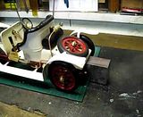
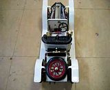
Mamod with leaking water gauge.
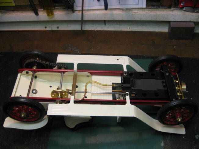
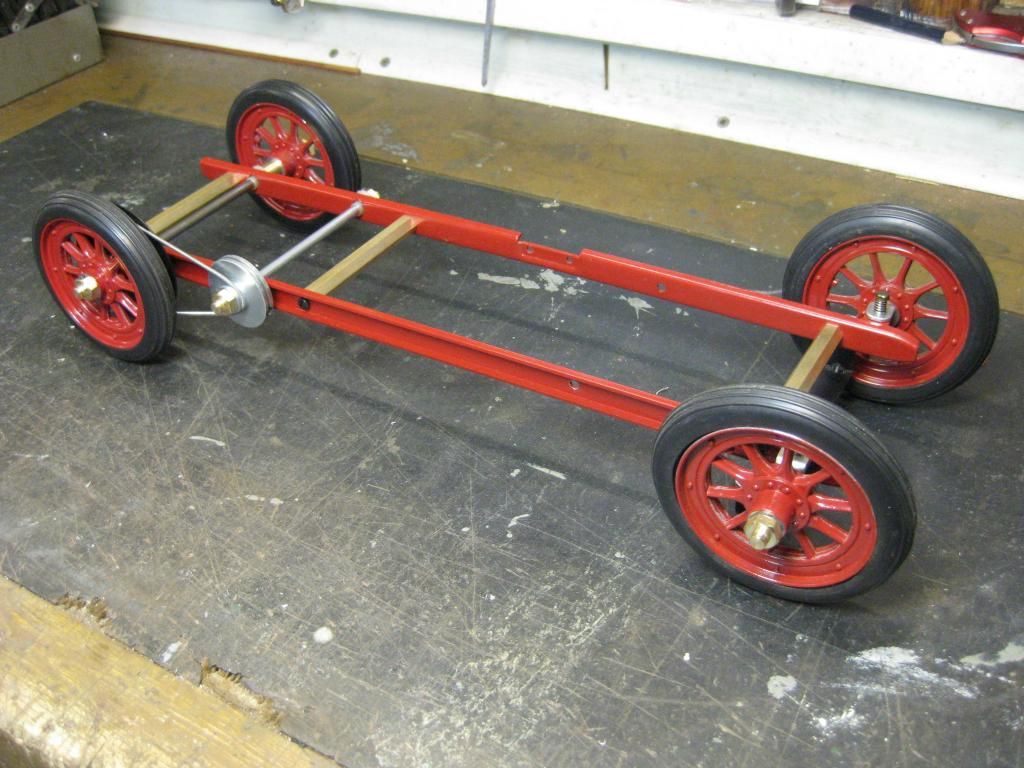
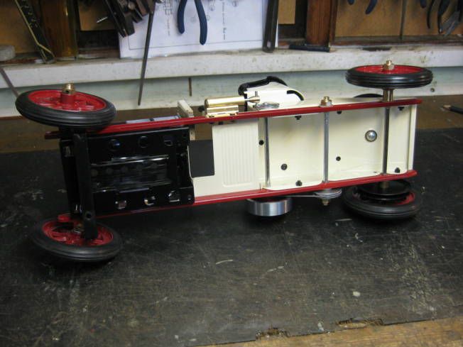
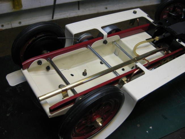
Chassis with temporary spacers fitted.
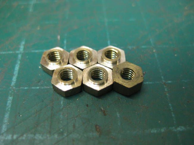
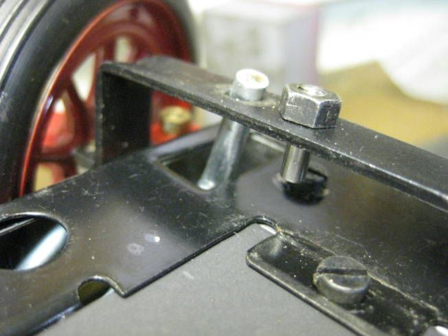
Shouldered nuts.
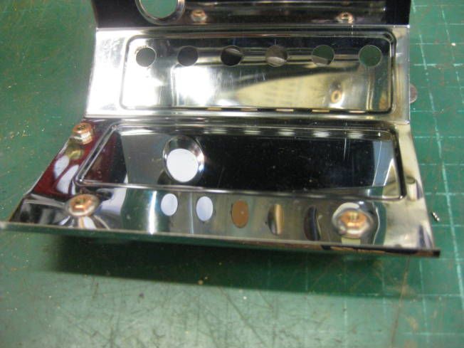
Shouldered nuts soldered in place.
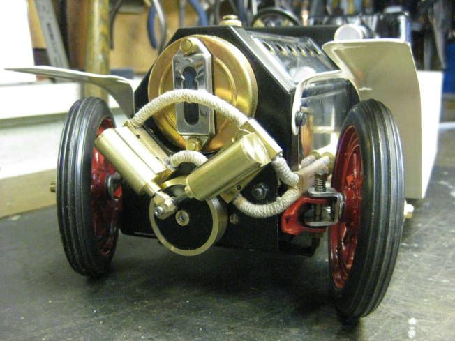
Assembled using screws.
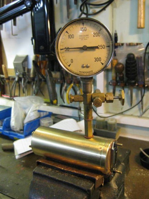
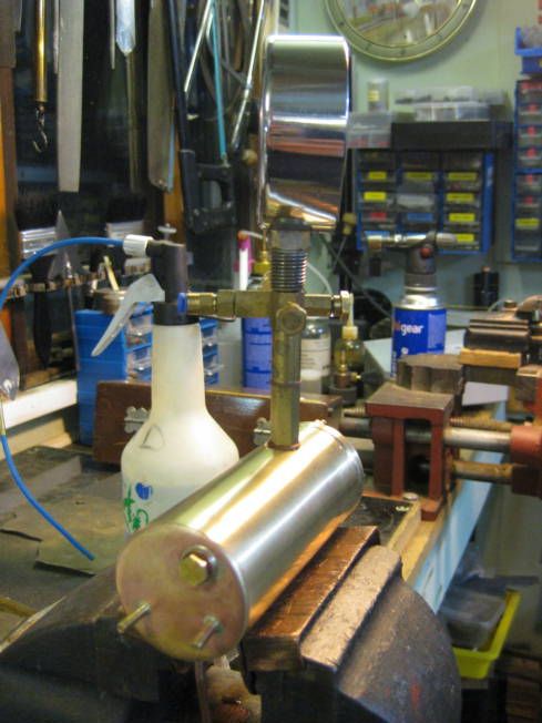
Boiler test after water gauge screws fitted.
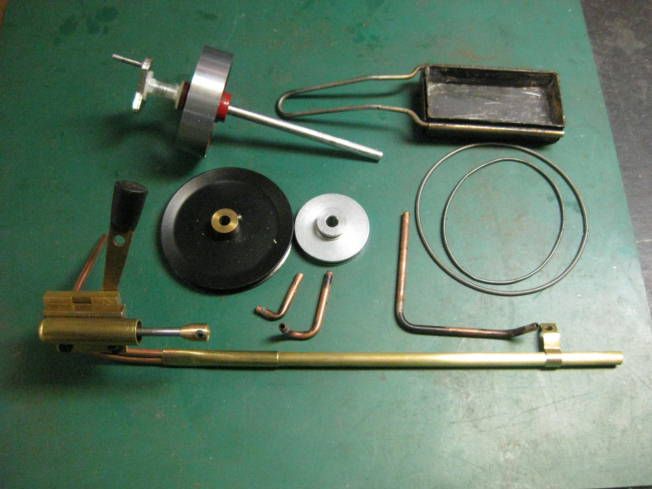
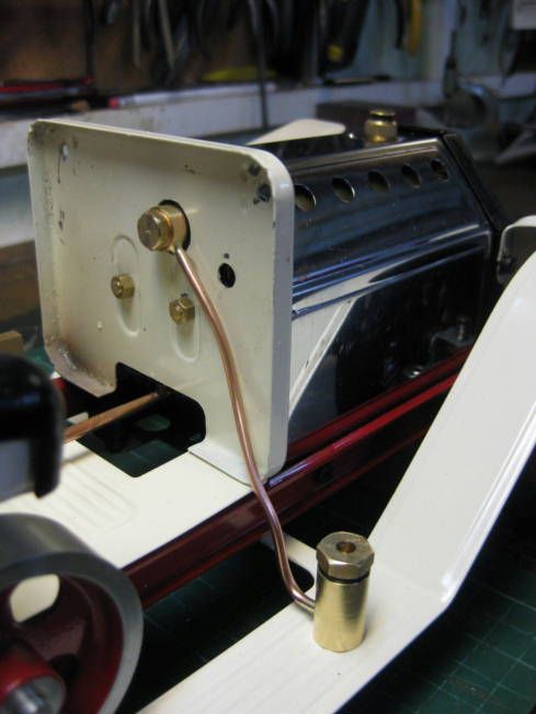
Bush for Goodall valve banjo fitting.
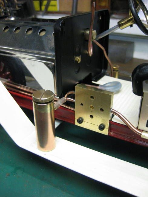
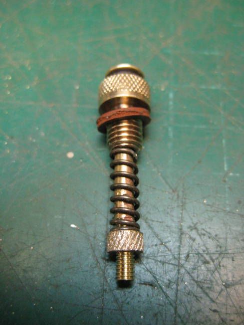
Goodall water top up valve.
Up rated safety valve.
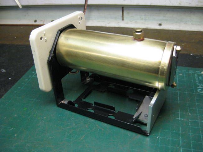
Split boiler frame.
Itala.
Stutz.
Gas tank.
Gas Tank fitted.
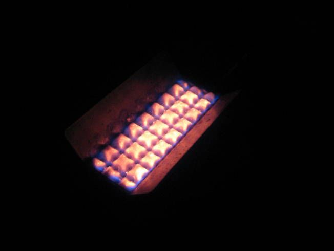
Burner lit.
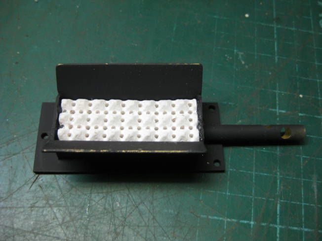
Burner.
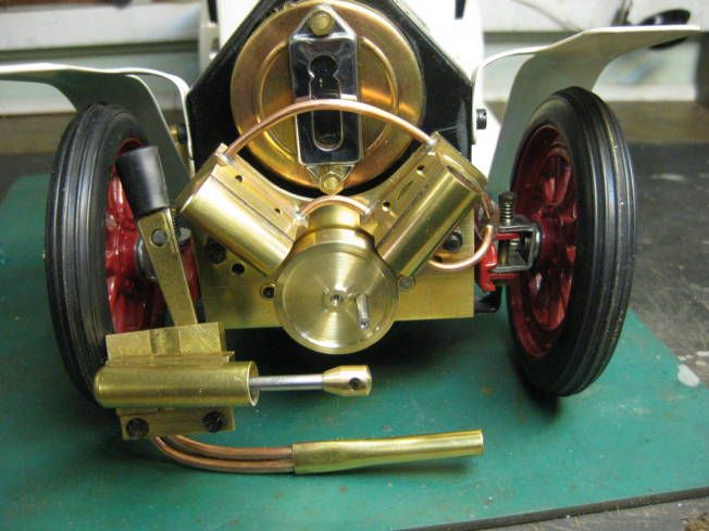
Exhaust pipe.
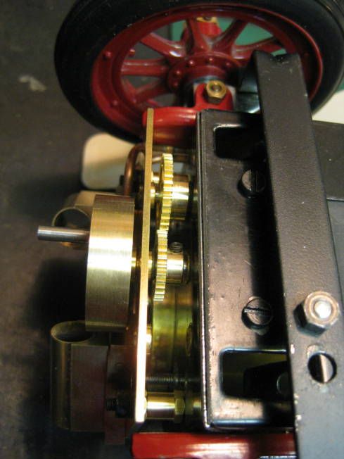
R/C drive pin.
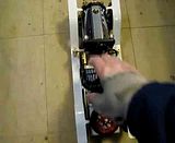
Video of bench test.
Video of floor test.
Regards Tony
Stage 1.
It started with a small steam weep from the water gauge on a Mamod SA1 steam car, which the repair of gradually got a bit OTT. Mamod water gauges had been repaired before but their model railway locomotives where it is fairly straightforward job. After removing the boiler from the locomotive the pop rivets which hold the gauge in place are drilled out. Brass screws are the put in the boiler from the inside and then soldered in place so replacing the rivets with screws, doing this allows any further mishaps with the gauge to be repaired without removing the boiler from the locomotive.
It was thought that it would be the same for the steam car as the gauge glass was also held in place with pop rivets. There was a major difference due to the difference in construct between the locomotive and the steam car the locomotive was screwed together but the car was totally held together with poprivets! Also it was necessary to almost take the whole car apart to access the boiler. So it was decided that after drilling out the rivets all of them would be replaced with screws. Other jobs that were done during the disassembly the cast wheels were eccentric so they were centred and bushed and their knock on retainers replaced with blind bushes held inplace with grub screws. Some of the rivets were in places where it was not possible to fit a loose nut so shouldered nuts were made and soldered in place. With this work done it was now possible to take apart and assemble the whole car easily. Another bit of a problem was that the steam pipe was soldered to both to the engine and boiler, which made them difficult to handle so the were unsoldered with the intention of using a union to connect them together again.
Now the part that caused all this work was repaired the boilers water gauge. It was found that the boiler had been silver soldered together unlike the previous Mamodboilers worked on which had been soft soldered. This allowed the pop rivet replacing screws also to be silver soldered and it was decided to fit a bush in the back head of the boiler for a banjo fitting connected by a pipe to a Goodall water top up valve. Most Mamod water gauges fail because the boiler has been allowed to run dry, fitting a Goodall valve makes it a lot easier to maintain a safe water level in the boiler. The boiler had been difficult to remove from its frame so the frame was split into two pieces which were then held together by some aluminium angle. The safety valvepressure was increased from about 15 psi to 25 psi.
As the boiler had been found to be silver soldered together it would stand extra heat so it was decided to replace the solid fuel tray with a ceramic gas burner, the gas tank being made to look like a petrol tank mounted behind the driving seat.
A certain amount of work was done on the engine fits, finishing the port block, enlarging steam ports and turning oil rings on the piston. It was thought that it would be fun to fit R/C to the steering so an actuating pin was fitted to the steering tie bar. The car was now assembled and without mudguards it looked a little like an Itala with the mudguards fitted it was something like a Stutz Bearcat. As the filler valve was to be fitted to the running board it went down the Stutz route.
The assembled car was now tested on the workshop floor and with a gas burner and with a higher boiler pressure it put in a credibleperformance. As designed it has a singleacting oscillating engine with a 5/16 bore and a ¾ stroke geared 10:1 to one of the rear wheels. The boiler produced more than enough steam for the engine, so thoughts were made about fitting adouble acting engine and going GT!
Stage 2 to follow.
Hopefully the following photographs will give an idea of the alterations.
Mamod with leaking water gauge.
Chassis with temporary spacers fitted.
Shouldered nuts.
Shouldered nuts soldered in place.
Assembled using screws.
Boiler test after water gauge screws fitted.
Bush for Goodall valve banjo fitting.
Goodall water top up valve.
Up rated safety valve.
Split boiler frame.
Itala.
Stutz.
Gas tank.
Gas Tank fitted.
Burner lit.
Burner.
Exhaust pipe.
R/C drive pin.
Video of bench test.
Video of floor test.
Regards Tony