


INTRODUCTION
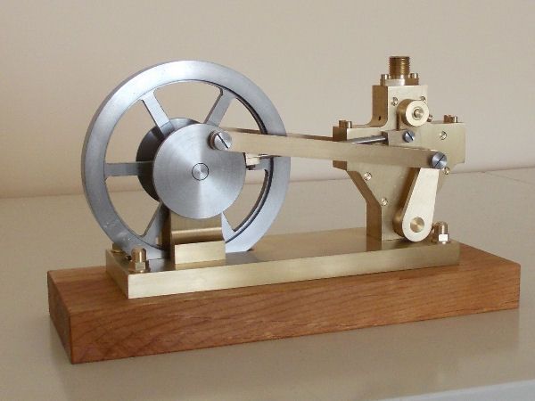
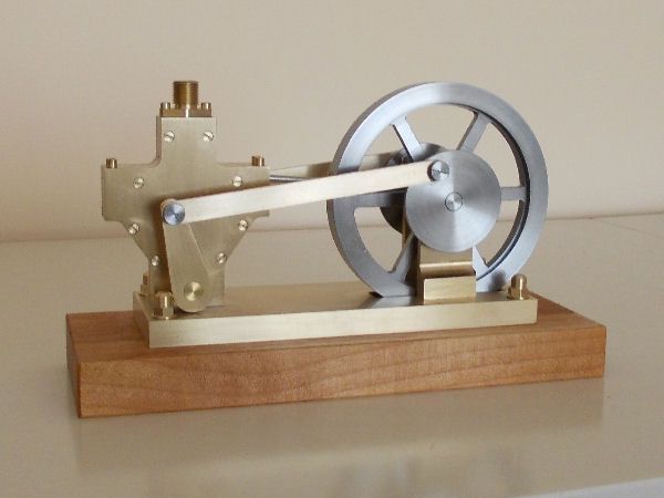
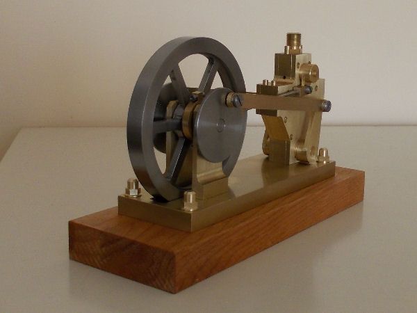
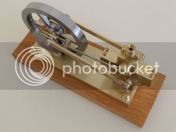
This post briefly describes a model Kimble Engine which I have just finished building. The inspiration to try a Kimble build came from Arnold's masterly build of Elmer's Kimble documented in a [thread=16036]thread[/thread] started in November 2011, and which I discovered in Nov 2015. Here are a few photos of my Kimble.
Here is a short video of the engine running.
DESIGN
Like Arnold, I have drawn heavily on Elmer's design, but I use metric units and have borne in mind the materials I had available. For example, the 9.6mm width of the Vane allows the Body, the Valve Holder and the Vane itself to be made from 10mm brass plate I already had. Similarly, the 90mm diameter of the flywheel allowed me to build it from a slice of mild steel bar I had.
Two points to note about the design are:
After completing the construction drawings with my usual CAD tool, I used the drawings to make a second 3D model of the engine using FreeCAD. Although I still find it unsuitable for estracting 2D drawings from a 3D model, FreeCAD has wonderful 3D modelling support.
Here is a short video with a screen capture of my simulation of the engine. In this model the front and rear covers of the engine are semi-transparent to allow observation of the Vane oscillating on its axis.
BUILD
I reckon that this engine is the most challenging I have attempted so far. Therefore, although I did not maintain a log during the build, I will mention a few aspects that may be of interest to some readers who, like me, do not have a milling machine or a rotary table.
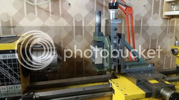
As shown in the above photo, to do rudimentary milling I bolt a sturdy angle plate on the cross-slide, then bolt the top slide on the vertical face of the angle plate and then bolt a machine vice on face of the vertical slide. This set up gives me Y (cross) and Z (vertical) excursions of 100mm with graduated index dials (0.02mm) on both axes. A home-made graduated dial on the tailstock end of the lathe's lead screw gives me the same precision when moving the carriage along the X axis (i.e. parallel to the lathe spindle axis). To set up this milling configuration with reasonable but not marvellous accuracy takes about 15 minutes. Going back to the normal turning configuration takes about 10 minutes. The photo also shows several wounds the vice has suffered while doing its duty!
Flywheel spokes This was my first attempt at a spoked flywheel, and I was determined to find a way to machine the surfaces forming the spaces between the spokes.
Three of the boundaries of each of these spaces are flat surfaces; the fourth is a segment of a cylinder concentric with the flywheel bore. Before making the spokes, I had already machined the Flywheel, completing to final size the boss (with its 7mm bore) and the web but leaving an excess of 0.2mm on the sides and outer surface of the rim. These surfaces of the rim were finalised on a mandrel after the spokes had been revealed.
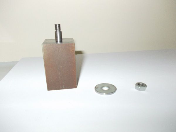
For the flat surfaces of the shapes, the technique I came up with is based on the use of a custom mandrel shown in the photo below. It has a big square shank and a nice big shoulder behind the 7mm spigot. With the lathe in the milling configuration, this mandrel was mounted in the machine vice, and it in turn held the flywheel firmly by its 7mm central bore. Thus by adjusting the Y and Z dials I could position the plane of the flywheel with respect to the axis of the lathe spindle, while by rotating the flywheel on the spigot of the mandrel, I could set the rotational angle of the flywheel with respect to the Y and Z axes.
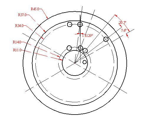
First, I drilled 30 holes through the web of the flywheel using the table of coordinates in the file DesignNotes.xlsx to accurately set the Y and Z coordinates without altering the rotational angle. For each of the six web shapes to be removed, there are five holes: one of 4mm at each of the four corners and one of 10mm in the middle to allow insertion of a hacksaw blade with a round section. With this setup, I also drilled and tapped the M3 hole for the screw that fixes the Eccentric to the boss of the flywheel. This hole was drilled through the washer holding the Flywheel on the Mandrel. Then I removed the flywheel from the mandrel and cut away the six shapes leaving about 0.5mm on all the edges.
Next, for each of the eighteen flat boundaries (three per shape), the flywheel was positioned so that the boundary was horizontal at a height of 2mm below the axis of the lathe spindle. This positioning was done by setting Z from data again prepared in DesignNotes.xlsx and with a 4mm rod held in the 3-jaw s.c. chuck to set the rotational angle by engaging the outer corner hole of the boundary. Then the boundary was milled with a 4mm end-mill using limits for the Y excursion from DesignNotes.xlsx.
The six curved boundaries were "machined" with the lathe in the turning configuration, the Flywheel held by the rim in the 3-jaw s.c. chuck, and a simple boring tool in the tool post. The lathe spindle was turned to and fro by hand, taking cuts about 0.02mm deep and advancing the tool by 0.04mm for each "fro". The process worked well, but took about 4 hours!
Making plate which is flat and of uniform thickness
A key requirement for the Body, the Valve Holder, the Covers and the Vane is that their outer faces be flat and parallel, and that their thickness between these faces be constant.
My first attempt to make a single chunk of brass plate about 75 x 65mm with such flat and parallel faces was made by bolting the chunk onto a faceplate (with bolt heads below the level of the plate's surface), facing off the outer face using a slow automatic feed on the cross slide, and then repeating the process with the chunk reversed on the faceplate. The finished surfaces looked and, as far as I could test, seemed to be flat. But they weren't parallel - as testified by my micrometre, the thickness varied steadily with a maximum difference of over 0.1mm! I am not sure why this was so; but suspect that bolting the chunk onto the face-plate was in fact causing the plate to bend slightly.
Back in the think tank, I decided to try using fly cutting with the lathe in the milling configuration. First, I prepared a rectangular block of aluminium 60mm x 70mm x 30mm with fly-cut faces and with threaded holes to receive the four countersunk bolts that would hold the brass plate against the block. In the photo at the beginning of this section on the Build, this Al block can be seen in the machine vice. Then I held the brass plate by its long edges in the milling vice to avoid bending, and used the fly-cutter to skim one of the surfaces. Next, I put the Al block in the milling vice and skimmed its outer surface with the fly cutter. Then, without altering the position of the Al block in the vice, I bolted the brass plate to the Al block with the skimmed surface of the plate against the skimmed surface of the block, and skimmed the other surface of the plate to get to the final thickness. This technique worked - as far as my instruments could tell, the brass plate was flat and of uniform thickness.
Setting up precise angles
The fabrication of several pieces requires setting of the piece up in the milling vice with a reasonably precise angle with respect to the normal to the axis of the lathe spindle. Examples are the sloping edges of the Vane Arms and the Valve Arms and the 5.32° angle of the grub screw hole of the Valve Arm.
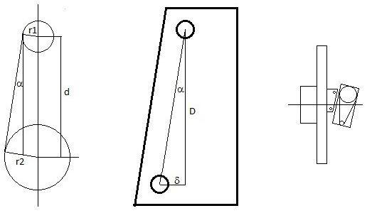
To do this I use wedges made from 5mm brass plate which a size of roughly 30mm x 25mm. The short edges of the wedge meet one of the long edges at a right angle, but the other long edge is angled. To use a wedge the piece must be prepared with an edge that has angle zero before being setup for machining the angled edge. As shown in the diagram below, during setup, the wedge is held between this edge of the piece and the surface of a face plate on the lathe's spindle.
The pic below shows some wedges, including those made for building my Kimble.
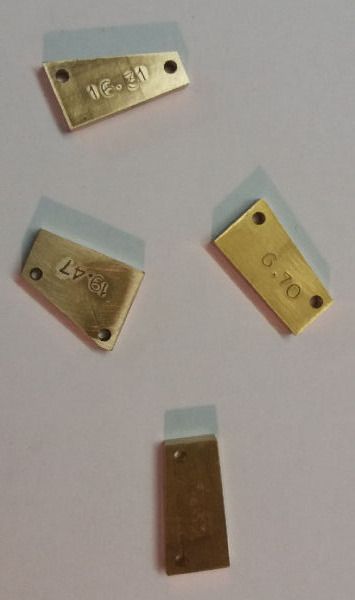
So the problem becomes - how to make a wedge with a precisely angled edge? I do it by first milling the three rectangular edges of the wedge and then, holding the wedge by its short edges normal to the lathe spindle axis, drilling two 3mm holes in precise horizontal and vertical relative positions. For example, for a wedge of height 30mm, a suitable vertical distance between the holes is 24mm. Then the horizontal difference between the positions of the holes must be 24 x tan(A) where A is the desired angle of the wedge. The precision derives from the use of the Y and Z graduated dials to set the positions for drilling. Once these holes are made, remove the wedge from the vice, roughly cut the angled edge about 2mm outside the holes, insert two short (30mm) pieces of 3mm rod in the holes and use these to set up the wedge in the vice so that the holes are equidistant from the faceplate. I use two 10mm x 10mm tool blanks between the faceplate and the rods. Then I complete the wedge by milling its angled edge, and stamping the value of the angle in degrees on one of the faces.
In the case of the Vane and Valve Arms, the requirement is that the angle be such that the angled edge is tangent to both of two arcs with different radii r1 and r2 and with a distance d between their centres. For such wedges the required angle is given by A = arc sin((r2-r1)/d).
Making the Spring for the Vane Seal
For this I copied Arnold's brainwave: I used one of the steel wires from a wire brush and bent it with the aid of two small pliers. Total manufacturing time: 2 minutes. Thank you Arnold. There are still over 400 wires left on the brush which cost me 4 euros. I still haven't decided whether to reckon the cost of the spring at 4 euro or at 1 cent....
CONCLUSION
Well thats it. I've enjoyed doing this engine and have also learned quite a few new tricks.
View attachment MyKimble Page 1.pdf
View attachment MyKimble Page 2.pdf
View attachment MyKimble Page 3.pdf
View attachment MyKimble Page 4.pdf
View attachment MyKimble Page 5.pdf
View attachment Design Notes.xlsx
This post briefly describes a model Kimble Engine which I have just finished building. The inspiration to try a Kimble build came from Arnold's masterly build of Elmer's Kimble documented in a [thread=16036]thread[/thread] started in November 2011, and which I discovered in Nov 2015. Here are a few photos of my Kimble.
Here is a short video of the engine running.
DESIGN
Like Arnold, I have drawn heavily on Elmer's design, but I use metric units and have borne in mind the materials I had available. For example, the 9.6mm width of the Vane allows the Body, the Valve Holder and the Vane itself to be made from 10mm brass plate I already had. Similarly, the 90mm diameter of the flywheel allowed me to build it from a slice of mild steel bar I had.
Two points to note about the design are:
- The line of mean position of the linkage between the Eccentric Strap and the Valve Arm is inclined with respect to the horizontal because the axis of the Valve Shaft is higher that the axis of the Crank Shaft. The angle is 5.32°. Thus when the Valve is in the middle of its stroke (inlet hole vertical), both the Eccentric axis and the Valve Arm axis have an angle of 5.32° off the vertical.
- I use milled flats on both the Crank Shaft and the Vane Shaft to achieve correct relative positioning of the Crank Disks and Flywheel/Eccentric on the Crank Shaft and the Vane Arms on the Vane Shaft. These flats greatly simplify the assembly of the engine.
- five PDF files, each with one A4 page of the construction drawings.
- an Excel file with a table of the holes for the flywheel fabrication and a table of the bolts, nuts, washers and sleeves.
After completing the construction drawings with my usual CAD tool, I used the drawings to make a second 3D model of the engine using FreeCAD. Although I still find it unsuitable for estracting 2D drawings from a 3D model, FreeCAD has wonderful 3D modelling support.
- Modelling in FreeCAD is parametric. FreeCAD doesn't remember the design you end up with; it remembers the steps you took to get there. So you can modify the values of the data you entered, like coordinates or radii or angles or whatever and, in a jiffy, FreeCAD will regenerate the design using these modified data values.
- FreeCAD contains a conceptual design tool called the Sketcher which includes a powerful constraint solver that finds a solution for a 2D sketch with points, lines, circles, arcs etc for which you have specified constraints like "this point must lie on this arc" or "this line must be tangent to this circle" or "the angle between these two lines must be 20 degrees", or "this line must be 23.5 mm in length", or "this line must be vertical" and so on. If your sketch is under-constrained then the Sketcher tells you how many degrees of freedom are left.
- FreeCAD allows you to write macros in the powerful language called Python, and your macro do anything you can do from the normal graphic user interface. In particular your macro can access and modify the parametric data values of the objects and the constraints of the sketches in your design.
Here is a short video with a screen capture of my simulation of the engine. In this model the front and rear covers of the engine are semi-transparent to allow observation of the Vane oscillating on its axis.
BUILD
I reckon that this engine is the most challenging I have attempted so far. Therefore, although I did not maintain a log during the build, I will mention a few aspects that may be of interest to some readers who, like me, do not have a milling machine or a rotary table.
As shown in the above photo, to do rudimentary milling I bolt a sturdy angle plate on the cross-slide, then bolt the top slide on the vertical face of the angle plate and then bolt a machine vice on face of the vertical slide. This set up gives me Y (cross) and Z (vertical) excursions of 100mm with graduated index dials (0.02mm) on both axes. A home-made graduated dial on the tailstock end of the lathe's lead screw gives me the same precision when moving the carriage along the X axis (i.e. parallel to the lathe spindle axis). To set up this milling configuration with reasonable but not marvellous accuracy takes about 15 minutes. Going back to the normal turning configuration takes about 10 minutes. The photo also shows several wounds the vice has suffered while doing its duty!
Flywheel spokes This was my first attempt at a spoked flywheel, and I was determined to find a way to machine the surfaces forming the spaces between the spokes.
Three of the boundaries of each of these spaces are flat surfaces; the fourth is a segment of a cylinder concentric with the flywheel bore. Before making the spokes, I had already machined the Flywheel, completing to final size the boss (with its 7mm bore) and the web but leaving an excess of 0.2mm on the sides and outer surface of the rim. These surfaces of the rim were finalised on a mandrel after the spokes had been revealed.
For the flat surfaces of the shapes, the technique I came up with is based on the use of a custom mandrel shown in the photo below. It has a big square shank and a nice big shoulder behind the 7mm spigot. With the lathe in the milling configuration, this mandrel was mounted in the machine vice, and it in turn held the flywheel firmly by its 7mm central bore. Thus by adjusting the Y and Z dials I could position the plane of the flywheel with respect to the axis of the lathe spindle, while by rotating the flywheel on the spigot of the mandrel, I could set the rotational angle of the flywheel with respect to the Y and Z axes.
First, I drilled 30 holes through the web of the flywheel using the table of coordinates in the file DesignNotes.xlsx to accurately set the Y and Z coordinates without altering the rotational angle. For each of the six web shapes to be removed, there are five holes: one of 4mm at each of the four corners and one of 10mm in the middle to allow insertion of a hacksaw blade with a round section. With this setup, I also drilled and tapped the M3 hole for the screw that fixes the Eccentric to the boss of the flywheel. This hole was drilled through the washer holding the Flywheel on the Mandrel. Then I removed the flywheel from the mandrel and cut away the six shapes leaving about 0.5mm on all the edges.
Next, for each of the eighteen flat boundaries (three per shape), the flywheel was positioned so that the boundary was horizontal at a height of 2mm below the axis of the lathe spindle. This positioning was done by setting Z from data again prepared in DesignNotes.xlsx and with a 4mm rod held in the 3-jaw s.c. chuck to set the rotational angle by engaging the outer corner hole of the boundary. Then the boundary was milled with a 4mm end-mill using limits for the Y excursion from DesignNotes.xlsx.
The six curved boundaries were "machined" with the lathe in the turning configuration, the Flywheel held by the rim in the 3-jaw s.c. chuck, and a simple boring tool in the tool post. The lathe spindle was turned to and fro by hand, taking cuts about 0.02mm deep and advancing the tool by 0.04mm for each "fro". The process worked well, but took about 4 hours!
Making plate which is flat and of uniform thickness
A key requirement for the Body, the Valve Holder, the Covers and the Vane is that their outer faces be flat and parallel, and that their thickness between these faces be constant.
My first attempt to make a single chunk of brass plate about 75 x 65mm with such flat and parallel faces was made by bolting the chunk onto a faceplate (with bolt heads below the level of the plate's surface), facing off the outer face using a slow automatic feed on the cross slide, and then repeating the process with the chunk reversed on the faceplate. The finished surfaces looked and, as far as I could test, seemed to be flat. But they weren't parallel - as testified by my micrometre, the thickness varied steadily with a maximum difference of over 0.1mm! I am not sure why this was so; but suspect that bolting the chunk onto the face-plate was in fact causing the plate to bend slightly.
Back in the think tank, I decided to try using fly cutting with the lathe in the milling configuration. First, I prepared a rectangular block of aluminium 60mm x 70mm x 30mm with fly-cut faces and with threaded holes to receive the four countersunk bolts that would hold the brass plate against the block. In the photo at the beginning of this section on the Build, this Al block can be seen in the machine vice. Then I held the brass plate by its long edges in the milling vice to avoid bending, and used the fly-cutter to skim one of the surfaces. Next, I put the Al block in the milling vice and skimmed its outer surface with the fly cutter. Then, without altering the position of the Al block in the vice, I bolted the brass plate to the Al block with the skimmed surface of the plate against the skimmed surface of the block, and skimmed the other surface of the plate to get to the final thickness. This technique worked - as far as my instruments could tell, the brass plate was flat and of uniform thickness.
Setting up precise angles
The fabrication of several pieces requires setting of the piece up in the milling vice with a reasonably precise angle with respect to the normal to the axis of the lathe spindle. Examples are the sloping edges of the Vane Arms and the Valve Arms and the 5.32° angle of the grub screw hole of the Valve Arm.
To do this I use wedges made from 5mm brass plate which a size of roughly 30mm x 25mm. The short edges of the wedge meet one of the long edges at a right angle, but the other long edge is angled. To use a wedge the piece must be prepared with an edge that has angle zero before being setup for machining the angled edge. As shown in the diagram below, during setup, the wedge is held between this edge of the piece and the surface of a face plate on the lathe's spindle.
The pic below shows some wedges, including those made for building my Kimble.
So the problem becomes - how to make a wedge with a precisely angled edge? I do it by first milling the three rectangular edges of the wedge and then, holding the wedge by its short edges normal to the lathe spindle axis, drilling two 3mm holes in precise horizontal and vertical relative positions. For example, for a wedge of height 30mm, a suitable vertical distance between the holes is 24mm. Then the horizontal difference between the positions of the holes must be 24 x tan(A) where A is the desired angle of the wedge. The precision derives from the use of the Y and Z graduated dials to set the positions for drilling. Once these holes are made, remove the wedge from the vice, roughly cut the angled edge about 2mm outside the holes, insert two short (30mm) pieces of 3mm rod in the holes and use these to set up the wedge in the vice so that the holes are equidistant from the faceplate. I use two 10mm x 10mm tool blanks between the faceplate and the rods. Then I complete the wedge by milling its angled edge, and stamping the value of the angle in degrees on one of the faces.
In the case of the Vane and Valve Arms, the requirement is that the angle be such that the angled edge is tangent to both of two arcs with different radii r1 and r2 and with a distance d between their centres. For such wedges the required angle is given by A = arc sin((r2-r1)/d).
Making the Spring for the Vane Seal
For this I copied Arnold's brainwave: I used one of the steel wires from a wire brush and bent it with the aid of two small pliers. Total manufacturing time: 2 minutes. Thank you Arnold. There are still over 400 wires left on the brush which cost me 4 euros. I still haven't decided whether to reckon the cost of the spring at 4 euro or at 1 cent....
CONCLUSION
Well thats it. I've enjoyed doing this engine and have also learned quite a few new tricks.
View attachment MyKimble Page 1.pdf
View attachment MyKimble Page 2.pdf
View attachment MyKimble Page 3.pdf
View attachment MyKimble Page 4.pdf
View attachment MyKimble Page 5.pdf
View attachment Design Notes.xlsx