Not so Baron.--Although the pivot arm swings in an arc, there is a connecting rod between the piston and the end of the pivot arm which is connected at each end with a round pivot pin.--This allows the piston to ride perfectly parallel to the bore of the cylinder.Hi Brian,
Has it occurred to you that the pistons may not actually be running exactly parallel to the bore. If you draw an arc from the centre of the pivot pin you will see that it follows a curve. This will cause the piston to want to rock up and down across its length. I suspect that this is where you are getting leakage.
You are using an out of date browser. It may not display this or other websites correctly.
You should upgrade or use an alternative browser.
You should upgrade or use an alternative browser.
A different opposed piston engine---
- Thread starter Brian Rupnow
- Start date

Help Support Home Model Engine Machinist Forum:
This site may earn a commission from merchant affiliate
links, including eBay, Amazon, and others.
BaronJ
Grumpy Old Git.
Not so Baron.--Although the pivot arm swings in an arc, there is a connecting rod between the piston and the end of the pivot arm which is connected at each end with a round pivot pin.--This allows the piston to ride perfectly parallel to the bore of the cylinder.
Ah yes I see the short connecting rod. :wall:
Just a wild thought.
By the way, where are the drawings ? I probably missed if you said.
Sorry I should learn to read... Found the link.
Baron--The download link is on post #192 of this thread.---Brian
sssfox
Well-Known Member
- Joined
- Mar 4, 2012
- Messages
- 183
- Reaction score
- 26
Brian,
With a Viton ring, if it is sized correctly, there is a seal completely around the piston, both behind and in front of the ring.
With a cast iron ring, there is a gap behind the ring and there is the gap between the ends of the ring. All of these places allow a little leakage. Your making the gap a little large doesn't help either. You may have fixed the last one when you made a two-piece piston.
Also, I don't know how much time you have on it, but the piston may not be completely seated in the cylinder.
While all of these issues may seem like problems, my experience has been that none of this matters when an engine is running. Everything happens too fast.
One other thought, did you seal the joint between the two halves of the piston?
I'm not sure of your design, but air could be leaking around the screw that holds the pieces together.
Steve Fox
Last edited:
sssfox--I think you are mixing my post up with Chuck Fellows post. I am using a Viton ring, on both pistons. Both pistons are one piece construction. The joint between the cylinders and the center block is also sealed with a Viton o-ring, and there is no leakage there.--Brian
For any of you who enjoyed this thread, make your way over to the website in this link and you can see this engine built to 1/2 scale by an excellent craftsman in New Mexico.
http://www.modelenginemaker.com/index.php/topic,3035.0.html
http://www.modelenginemaker.com/index.php/topic,3035.0.html
I am setting here in the middle of a construction zone, while the home renovation guys work around me. They finished the new laminate floor in my office yesterday, so I was able to get my computer and all of its associated bits hooked back up in my office. The office and main basement are all newly painted and all of the flooring has now been installed. They have done a very impressive job. While snooping around yesterday through all of my boxes of engine parts and strange objects, I see that when I got the original two Viton O-rings for the opposed piston engine, I actually purchased four, in case I destroyed one while installing the pistons into the cylinders. That's a good thing, because once the construction moves on and leaves me in peace, I will put the two new rings onto the pistons and see if that cuts down on any of the compression leakage. This is a fairly major job, because like the cam gear, the whole engine must be disassembled to get the pistons out of the cylinders. I have no desire to do any more engine building at the moment, but would like to move back onto my "marble automation" and finish it up so I can have a video of it running, being powered by the opposed piston engine. I have to finish the return ball tracks on it and mount few more "gadgets" before I consider it finished. I also want to try a new condenser on the engine, because as many people pointed out, there is a lot of arcing going on at the ignition points. --Brian
- Joined
- Dec 31, 2010
- Messages
- 777
- Reaction score
- 195
Hi Brian:
Yes, it seems to run really well on that carb. I 'm glad you found one that works. The engine is a realy nice piece of work.
Did George post the plans for that carb on the forum or did you make it from some of his plans that you had previously?
Good stuff
Sage
Yes, it seems to run really well on that carb. I 'm glad you found one that works. The engine is a realy nice piece of work.
Did George post the plans for that carb on the forum or did you make it from some of his plans that you had previously?
Good stuff
Sage
George has posted the plans on this forum. Its a one page sheet, titled (I think) Air Bleed Carburetor. I Found it rather difficult to get my head around until I modelled the parts and assembled them, because there is no assembly drawing on the one page sheet. I had to resort to doing an internet search for videos of George's 4 cylinder engine running with that carb on it to see how it went together. Then George found out what I was doing and sent me four or five pictures of it installed on his engine, which was very kind of him. The problem for me was that George's original carb plans had a .260" bore to feed four cylinders. I had to dick around with the plans and reduce it to a .156 bore to suit small one cylinder engines. In doing so, I found that it was more suitable to have the air bleed screw accessible from the top side of the carb than from the bottom. Over on my very recent thread on building the carb, I posted a download link to all of the modified drawings as pdf files.----Brian--This is George's drawing.
http://www.homemodelenginemachinist.com/downloads/files/4_CYL_OHV_SHT_J.pdf
http://www.homemodelenginemachinist.com/downloads/files/4_CYL_OHV_SHT_J.pdf
Last edited:
- Joined
- Dec 31, 2010
- Messages
- 777
- Reaction score
- 195
Thanks Brian:
You're a hard guy to keep track of having multiple threads on the go. I'm going to have to check on you more often
Nice work on the Carb. Looking forward to following your next adventure. Your reporting style makes it interesting to follow along.
Good work.
Thanks
Sage
You're a hard guy to keep track of having multiple threads on the go. I'm going to have to check on you more often
Nice work on the Carb. Looking forward to following your next adventure. Your reporting style makes it interesting to follow along.
Good work.
Thanks
Sage
robcas631
Well-Known Member
Every night this week I have come home from the temporary "on site" engineering contract I am working and started this engine. This is the part of building a new engine that I always have mixed feelings about. Its coming down from a big "high", pleased that the engine runs as well as it does, and relieved that I don't have to spend every spare moment of my life machining something.---But a bit lost as to what to do now that the engine is finished. I get totally burned out every time I build an engine. I don't want to build anything for a while now--just live vicariously by reading everybody else's build posts. The trouble with building successful engines, is that ordinary engines become, well, commonplace. This tends to push me towards more exotic and "different" engines. All I really want right now is for this seemingly endless winter to be over and some warm weather. I know I will build something else---but hopefully not for a while now.----Brian
Well said about getting burned out. I carve, paint and am designing a new boat for the summer.
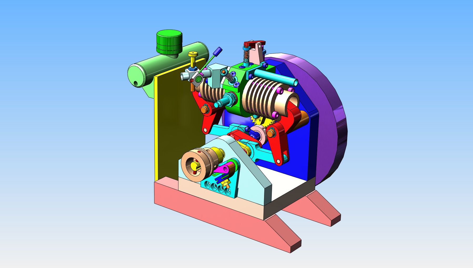
I am thinking of making some modifications to this engine. I would like it to idle down as slowly and run as consistently as the Webster does. I think part of the problem (possibly a large part) is the small diameter mega thick flywheel. The current flywheel is 3.875" diameter x 1.625 thick. This adds up to a weight of 5.42 pounds. I am considering adding a 3/4" thick x 6" diameter ring to the outer diameter of the original 5/8" thick flywheel, which will give a total weight of about 5.5 pounds, without the two 1/2" thick pieces that were added when I was trying to get the engine to run. This weight will be positioned much closer to the crankshaft bearing and the good part is that the weight will be spread over a larger diameter, which will make the inertial effect of the flywheel much greater than it currently is. Of course this means that I will have to move the gas tank, cut the extension off the back side of the baseplate, and add a couple of "risers" under the baseplate so the flywheel will clear the table.


Last edited:
- Joined
- Dec 31, 2010
- Messages
- 777
- Reaction score
- 195
Hi Brian:
I've forgotten what's on the flywheel side of the vertical plate but just to give it a try first, why not place the engine along side the edge of the table and put a temporary large diameter flywheel on it hanging below the table top and see what difference it makes.
Adding only and extra .1 pounds or 2% (your calculations) doesn't sound like it would make much difference. I'd hate for you to cut and hack it only to find it make little difference.
Once you know how much weight you need maybe you can hollow out some of the one you have and pour some lead into it.
Sage
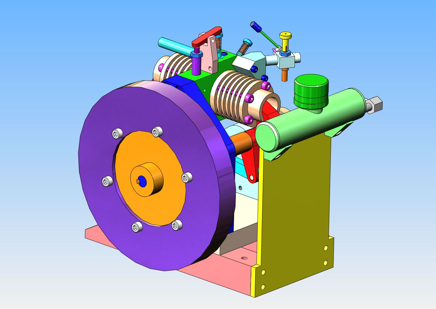
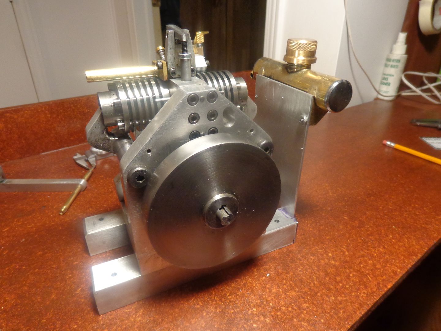
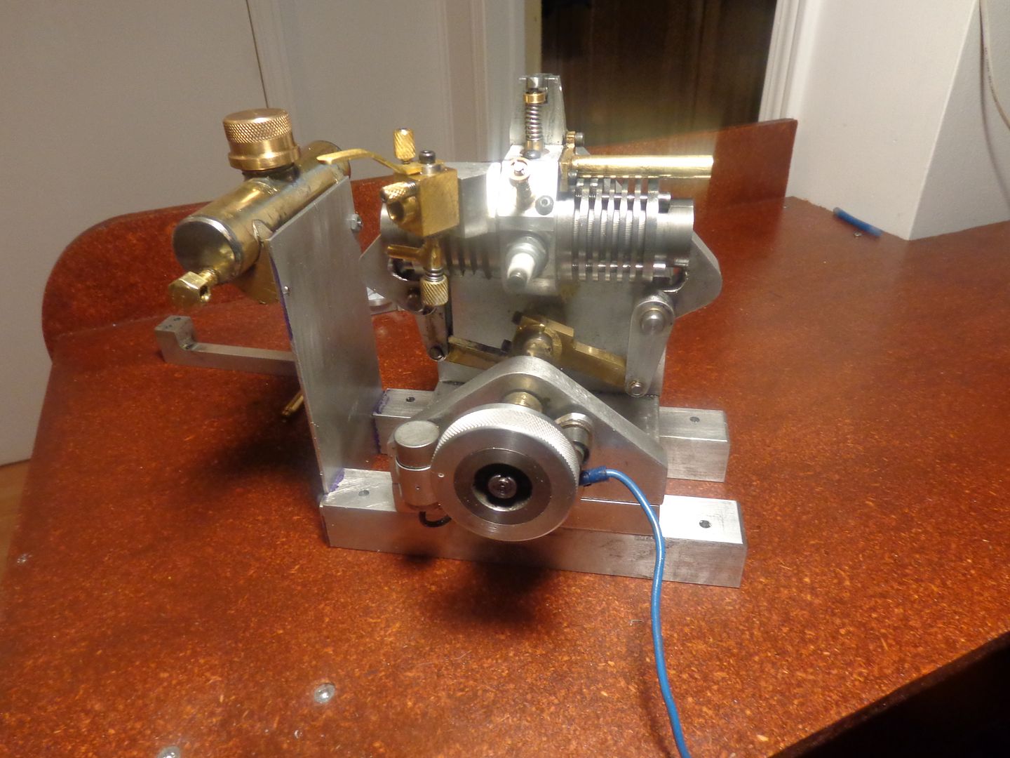
Dsage--The largest flywheel I could use was 3 7/8" diameter, because the baseplate extended out beyond the main backplate. Today I have removed the flywheel and trimmed the extended baseplate flush with the back side of the main backplate. Now I can put a larger flywheel on it, but the flywheel will extend down lower than the baseplate. That is why the pinkish color skids are bolted to the bottom of the baseplate---To get the flywheel up high enough to not hit the table. I think increasing the flywheel diameter from 3 7/8" to 6" is going to make a big difference, even though the overall weight will be the same. Later this week I will know.
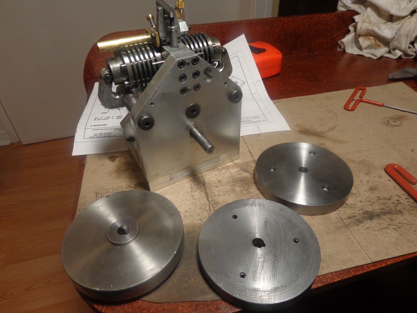
Poor little guy---Kinda looks like a bulldog pup with its tail docked!! I removed all the flywheels and trimmed the baseplate off with my bandsaw, then set the whole engine up on an angle plate in the mill and milled the remaining bit of plate off flush with the main backplate. The two plain flywheels will be discarded. The flywheel with the center boss on it will receive a ring of mild steel 6" diameter x 3/4" thick added to its outer diameter. I managed to trade a bit of mechanical design for a laser cut ring of 1018 mild steel, but I won't have it until Wednesday. Tomorrow I will make up the two new pieces which fit under the baseplate.


Last edited:
Now I have room for a REAL flywheel!!! (That's the original flywheel shown on there). At the very last minute I decided not to but a taper on the end of the "bunks" under the baseplate. It might have looked a bit nicer, but I wouldn't have been able to use a C-clamp on it to hold it in place on my reference desk, and now that I have cleaned the desk up and put a new top on it, I didn't want to drill any holes in it.


- Joined
- May 27, 2010
- Messages
- 2,999
- Reaction score
- 1,171
Please post video. With a bigger flywheel slow speed iding would possible??
Pulling out the last few lazy bones.
Pulling out the last few lazy bones.
Gus, the effectiveness of a flywheel is very much tied in to the diameter. According to what I have read 90% of the flywheels effectiveness is concentrated in the outer rim of the flywheel. The larger that rim is in diameter, the more effective the flywheel will be. All single cylinder four stroke engines have an inherent "flaw" in their design. Namely, once the cylinder has fired and the piston has reached the bottom of the stroke, there is absolutely no outside forces to bring the piston back up to top on the exhaust stroke, down again on the intake stroke and up again on the compression stroke. For that a flywheel is necessary. If the flywheel is too light or too small in diameter to carry out this work, then the engine will stall before it can go through all of the necessary moves to let it fire again.--And this ties in directly to how low a speed the engine can run at. A small diameter but very thick flywheel like I originally had on this engine is nowhere near as effective as a flywheel of the same weight, but thinner with a larger diameter.--Brian
Similar threads
- Replies
- 25
- Views
- 3K


