A different opposed piston engine---

Home Model Engine Machinist Forum

Help Support Home Model Engine Machinist Forum:

This site may earn a commission from merchant affiliate links, including eBay, Amazon, and others.
What a privilege to be able to follow this engine build from the concept stage to the final, running stage....and, in less than two months. What an incredible effort it took, not to mention the dedication, all the machining, thinking, photographing, posting explanations, suffering frustrations, the joyous triumphs, the tweaking, the expense of materials..... etc.

Thank you for a wonderful tutorial. I'm sure I, and others have learned much from following this build. I commend you for allowing us to see all the failures, and then let us see how the multitude of unforeseen problems were solved.

Truly, a machining, and educational, tour de force.

Congratulations on your success.


Frank
 
Brian,

You must be in 7th heaven! When all the hard work brings metal to life. For me watching this build is inspirational and educational. Well done Sir!
 
Brian:

It must be a real rush to have and engine you've only ever seen on paper actually turn into an animate object. And a really good running one at that! The fact that it runs at all is testament to your design abilities.

Good job!!

I hope you'll continue a bit on this thread so we can see what you work out with the carb.

What we all need is a good carb design that can be assured to work. There is no shortage of carb drawings out there. Certainly Strictly IC magazine had one in every other issue. But how many good ones is another story.

Thanks for sharing with us. It's a lot work and we appreciate it. :)


Sage
 
The engine runs, and I am indeed happy with that fact. However, running and running well are two totally different animals. I want it to be able to run very smoothly, ticking over slowly like a finely tuned motorcycle engine, yet able to be revved up by a tweak of the throttle. I will post my attempts to get to that point from where it currently is. Currently the engine is running too fast, and it is fighting to get through two complete revolutions of the crankshaft and fire again before it stalls out and quits. Posts may be slow in coming, because it is miserably cold here, and my "test bench" is out in the main unheated garage. I have an electric furnace in the main garage, but it uses a fearsome amount of electricity to keep it heated. However, slow though the ride may be, I will post about my progress and hopefully reach the point where the engine runs the way I want it to.----Brian
 
Brian,
I look forward to your sorting out the problems because I know it will be a learning experience, and I will be patiently waiting. I know how cold an unheated shop/garage is up north. I ONCE tried to run my Upshur vertical at 19 F never again will I screw up my carb settings that much.
Art
 
I just got my feeler gauges out and checked, and found that my valve lash had slipped/changed to a whopping 0.023"!!! I am changing it to .005" to see what effects that has on when the valve opens and closes without changing anything else.
 
Okay--That clinches it--There is something wrong with the machining of my cam, but not with the design of it. I set the lash at .005", and readjusted the timing so that the valve lifter just began to contact the valve at 50 degrees before bottom dead center, (which corresponds with the 1/8" of final piston travel before bottom dead center. I then rotated the crankshaft by hand until the piston began its travel up the cylinder on the exhaust stroke. The exhaust valve opened fully as it was supposed to--and then stayed open through most of what should have been the intake stroke as the piston travelled back down the cylinder. I have messed up the machining of the cam. I'm surprised that the engine ran at all. So--this weekend I will machine a new cam. I knew there was a reason I designed this engine to have a bolt on cam!!!
 
Jeez--What a nasty little piggy to take the cam off of. I almost had to dismantle the entire engine!!! I can't really see anything wrong with the cam on visual inspection, but at this level there isn't really too much that would be visible to the naked eye anyway. Maybe if I had a visual comparator it would show up.--Oh well, it gives me a chance to clean up the engine.

[/URL
 
Somehow, a Demon got into my lathe!! I just checked the outer diameter that the brass gear has for the cam to fit on against the inner diameter of the gear. There was a discrepancy of .008 total runout where there shouldn't have been any. That along with the angles on the side of the cam being out of spec, probably has a lot to do with the weirdness I am seeing in my valve opening/closing. Since I have everything apart anyways, I am setting the gear up on a mandrel and turning a bit off the o.d. off the shoulder to bring it back to concentricity. Then I will bore the new cam "to suit".
 
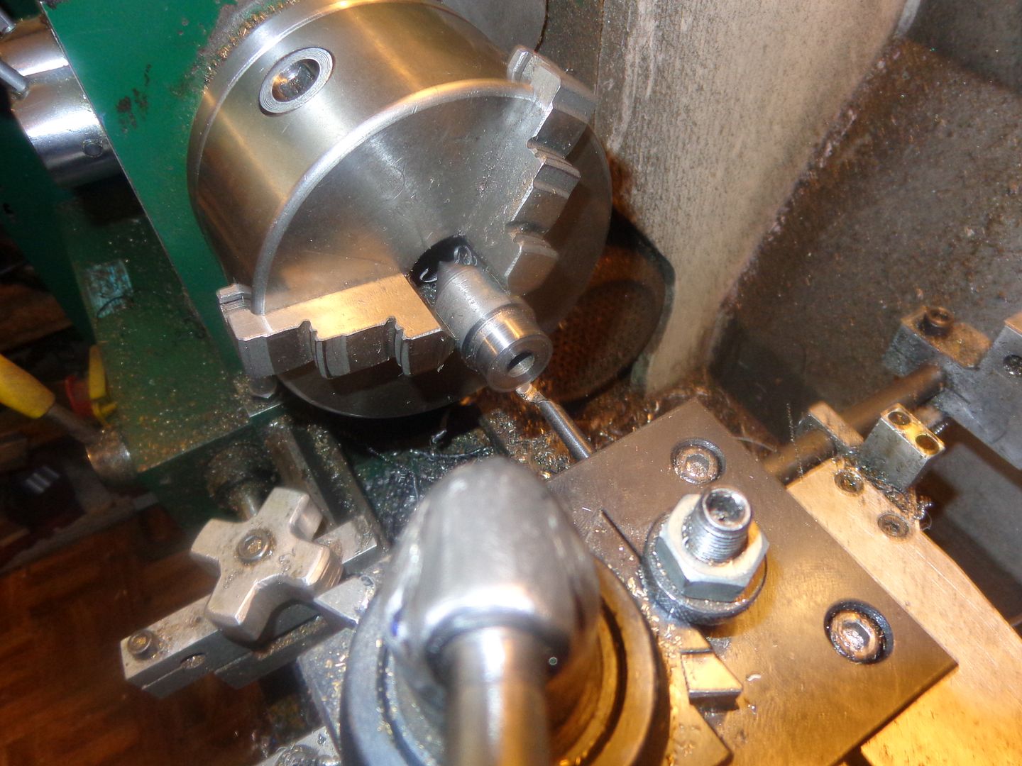
First step to get out of this mish-mash is to true up the "spigot" on the face of the gear to be concentric. Accomplished this by using 638 Loctite to attach gear to a 1/4" cold rolled shaft, letting it set up for two hours, then doing a skim pass on the spigot. Bore on the gear is 1/4" and its a reamed hole. Now outer diameter of spigot is perfectly concentric to bore of gear, at least within the limits of my 3 jaw chuck, which has about .003" total runout--that's about .0015 out of center, which is pretty well standard for a 3 jaw chuck. I used my 3/32" cut off blade to do the truing cut, because I didn't want to leave any radius in the corner.
 
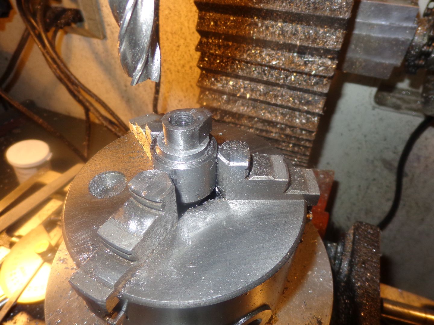
Next step is to find a piece of 1" cold rolled steel, turn the outer diameter down to .875" which will be the major diameter of the cam, and then bore a center hole. I had to drill and then bore the center hole to match the "spigot" on the gear, because now it is a non-standard size and I don't have a reamer that was the right size. I stepped back 5/16" from the face and used my cut off tool to make a fairly wide register about .080 deep so that when I set up in the mill I will have a good guideline on how deep to mill the flanks of the gear.
 
I might suggest that you could chuck a piece of stock and turn a spigot to fit the bore of the gear. This would eliminate chuck runout, for the cost of a small piece of stock. I did just this to rework some parts last week because I had no way to hold other than a shallow bore deep in the back of the part.
 
Hi Brian:

Fixing the cam timing issue is going to make your carb work better too. As it is (was) with the exhaust open for most of the intake stroke you probably had very little vacuum to a) open the valve and b) suck fuel through the carb.

Intake valve spring may need some tweaking now too.

This should be interesting. Watching with great interest.

Thanks

Sage
 
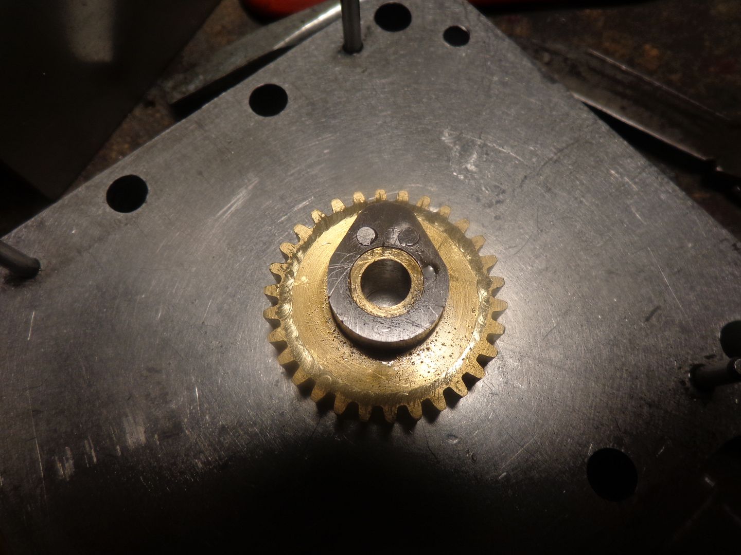
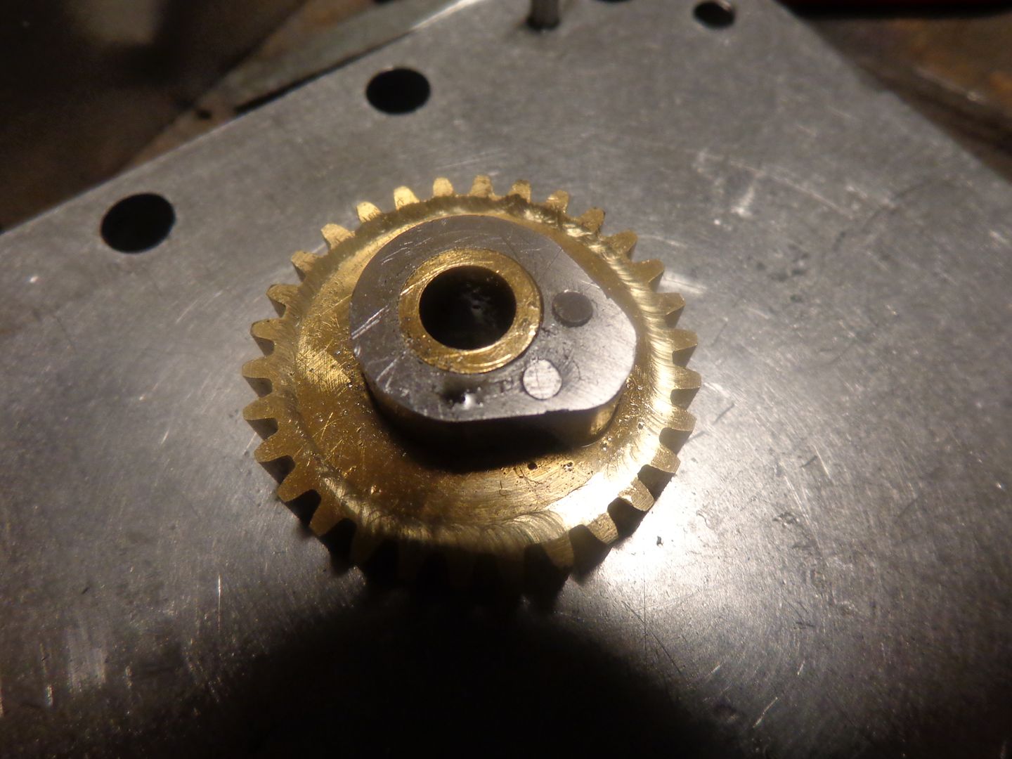
This is as good as it gets around my house!! The angle is correct, and I'm pretty sure the holes are in the right place for my #4-40 screws. I know it fits the "spigot" on the brass gear because I've had it on there. Lord, Lord, I wish I had read-outs for this kind of work. It is SO easy to lose track of where you are and keep having to go back to "center" things under the quill!!! Barring unforeseen disasters and broken taps, I will have the cam and gear back together tomorrow morning.--Thanks for looking.---Brian
 
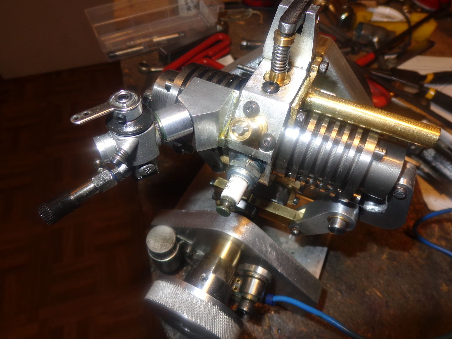
Very pleased to announce that everything is back together, and this time the exhaust valve really is operating exactly as it is supposed to. Begins to open at 50 degrees before end of power stroke (which is almost exactly 1/8" before piston reaches bottom dead center). Opens fully and stays open during exhaust stroke, and closes fully about 20 degrees into the intake stroke. Even with all of the mating surfaces on the plate framework located with dowel pins the engine has stiffened up a lot after complete disassembly and re-assembly, but I expected that to a degree. It is nowhere near as stiff as it was after first assembly. Before I try to run it again I am going to make a new adapter to go between the carburetor and the intake manifold. Right now there are two adapters in there, which I will replace with one much shorter adapter. I also want to do something about the routing of my gas-line so I don't have to resort to tying it up out of the way with a string, as seen in the last video. One really good sign is now that when I turn it over slowly with the electric drill or by hand, the intake valve makes a noise. Its a strange sound, kind of a combination of a gooses honk and a pigs fart!!! That indicates that the exhaust valve is sealing well and the rings are sealing well, and that atmosphere is being sucked in through the intake valve and manifold.
 
Last edited:
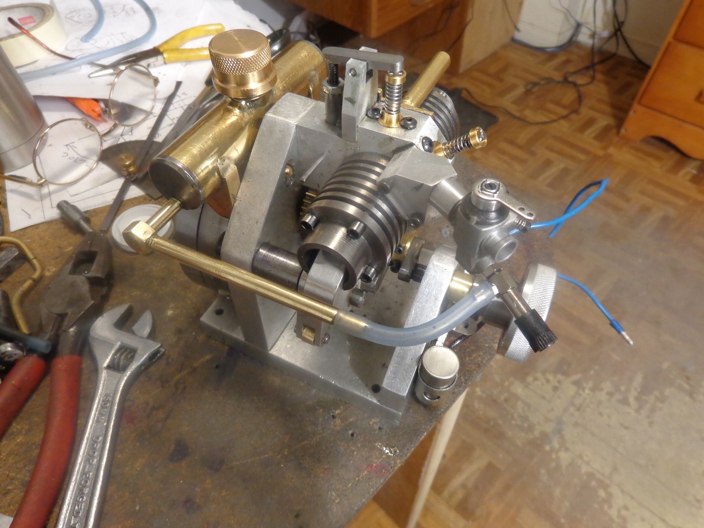
The best laid plans of mice and men--I really couldn't find a good way to run the gas line from where it came through the backplate to the carburetor. I was terribly afraid that the flexible gas line would get caught up in all of the flailing pivot links and connecting rods and shower me with blazing gasoline. I plugged the original exit from the tank, and drilled and tapped one of the endplates 1/4"-20. That allowed for a new rigid gas line. I had a go at bending some brass tubing, but after the third kink I gave up in disgust and used some solid brass that I had to make 1/4" diameter "lines" with a .080 hole drilled full length. It isn't really apparent in the picture but it clears the pivoting link by about 1/4". I think I will put a support on the brass tube which connects to the flexible gas line and tie it back to the base with s 3/16 rod just to prevent any vibration before I start the engine again.
 

Latest posts

Back
Top