


This post briefly describes a simple system for cooling and lubricating the cutter and work piece being machined on my lathe. The need for some cooling became apparant during the rough machining of the steel chunk destined to becaome the Body of a Quick Change Toolpost (see thread "Another Quick Change Toolpost").
For convienience of references, I have named this Cooling and Lubricating system, "Coolube".
My basic requirements for Coolube were:
Requirement 1. Keep it simple and reliable.
Requirement 2. Be able to apply the fluid flow at the point of contact between the tool and the work piece in two main usage scenarios:
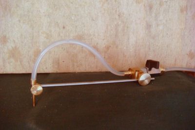
a} the work piece is turning (chuck, faceplate, ...) and the tool or cutter is visible and moves with the carriage; in this case the point at which fluid is required moves with the carriage.
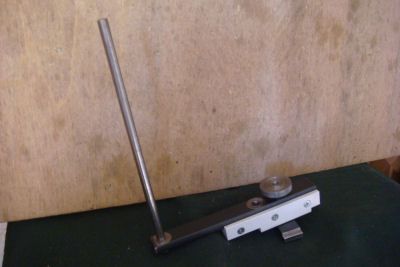
b} the work piece is fixed to, and moves with, the carriage and the cutter is visible and is turning, typically held in a chuck or in a fly cutter; in this case the point at which fluid is required is fixed at the business end of the cutter.
There are of course scenarios in which the point of contact between tool and work piece is not visible as when drilling or boring.
Coolube has the following components:
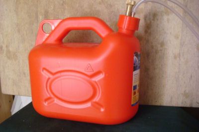
Component 1. Fluid Tank. Holds the fluid ready for use. It is positioned on a shelf about 80cm above the lathe so that the flow is powered by gravity. The tank is a 5 litre plastic can of the type suitable for transport of petrol. Its sealing cap has a funnel with a screw-on lid for refilling, a tube which comes from the bottom of the tank for syphoning the fluid down to the lathe, and a tube from above the fluid into which I puff to start the syphoning action.
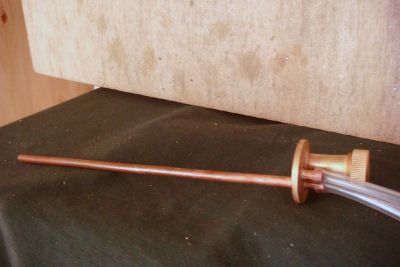
Component 2) Dribbler. Contains an orientable nozzle on the end of a steel arm, a tap for regulating the flow, and a block for fixing the Dribbler to an 8mm vertical bar. The fluid inlet is connected to the syphon tube of the Tank.
Component 3) Fixed Support. Allows an 8mm vertical bar to be mounted quickly at any free point of the lathe bed. Fabricated from steel, brass and PVC.
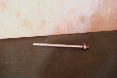
Component 4) Moving Support. An 8mm vertical bar with a lock nut which can be quickly mounted of the compound slide of the carriage using existing threaded holes. Steel
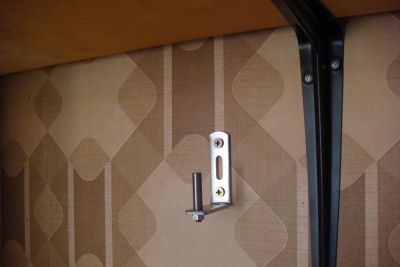
Component 5) Wall Support. Used to mount the Dribbler out of the way when not in use.
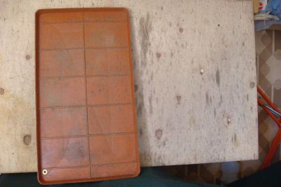
Component 6) Tray. A plastic tray, cut from a retangular base for garden vases, to collect the fluid and the metal droppings. At the front, left corner of the bottom there is outlet which protrudes about 10mm below the bottom of the Tray. The tray can be quickly removed from its position for cleaning.
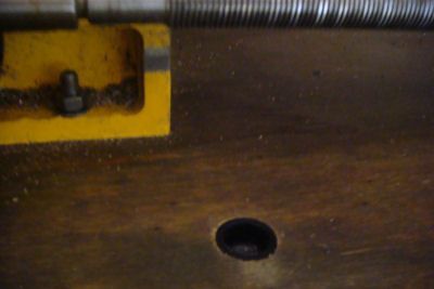
Component 7) Drain. A amsll plastic cup sunk into the table on which the lathe is mounted. The outlet of the Tray fits loosely into this cup.
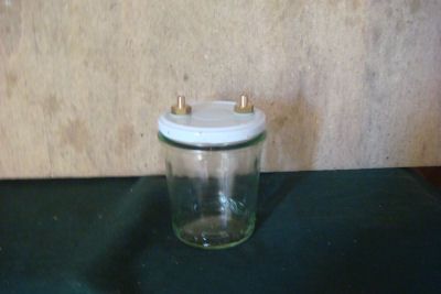
Component 8) Filter. A jam bottle with a screw tight lid fitted with inlet and outlet nipples. Mounted on the wall behind the lathe so that it is well below the Drain and well above the Bucket. The inlet is connected to the outlet of the Drain. The flow of fluid is sufficiently slow to give the metal droppings time to sink to the bottom.
Component 9) Bucket. A second 5 litre plastic can to collect the fluid arriving from the Filter. Sits on the floor behind the lathe.
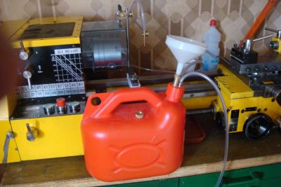
The image below shows illustrates the operation of filling the Tank with fresh fluid or with recycled fluid from the Bucket. The tap of the filling spout can be seen on the Tank.
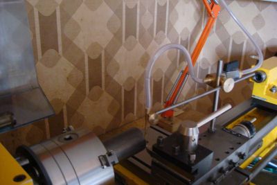
The following two images show the operational configuratione of Coolube corresponding to the Scenarios described at Requirement 2 above.
Moving Point of Application
Fixed Point of Application
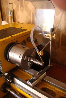
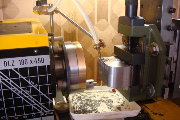
The final image shows Coolube in use while flycutting a meaty chunk of steel. The configuration used is the Fixed Point of Application.
I hope this brief desciption is clear and of interest. I will be grateful for any comments and suggestions.
Ian
For convienience of references, I have named this Cooling and Lubricating system, "Coolube".
My basic requirements for Coolube were:
Requirement 1. Keep it simple and reliable.
Requirement 2. Be able to apply the fluid flow at the point of contact between the tool and the work piece in two main usage scenarios:
a} the work piece is turning (chuck, faceplate, ...) and the tool or cutter is visible and moves with the carriage; in this case the point at which fluid is required moves with the carriage.
b} the work piece is fixed to, and moves with, the carriage and the cutter is visible and is turning, typically held in a chuck or in a fly cutter; in this case the point at which fluid is required is fixed at the business end of the cutter.
There are of course scenarios in which the point of contact between tool and work piece is not visible as when drilling or boring.
Coolube has the following components:
Component 1. Fluid Tank. Holds the fluid ready for use. It is positioned on a shelf about 80cm above the lathe so that the flow is powered by gravity. The tank is a 5 litre plastic can of the type suitable for transport of petrol. Its sealing cap has a funnel with a screw-on lid for refilling, a tube which comes from the bottom of the tank for syphoning the fluid down to the lathe, and a tube from above the fluid into which I puff to start the syphoning action.
Component 2) Dribbler. Contains an orientable nozzle on the end of a steel arm, a tap for regulating the flow, and a block for fixing the Dribbler to an 8mm vertical bar. The fluid inlet is connected to the syphon tube of the Tank.
Component 3) Fixed Support. Allows an 8mm vertical bar to be mounted quickly at any free point of the lathe bed. Fabricated from steel, brass and PVC.
Component 4) Moving Support. An 8mm vertical bar with a lock nut which can be quickly mounted of the compound slide of the carriage using existing threaded holes. Steel
Component 5) Wall Support. Used to mount the Dribbler out of the way when not in use.
Component 6) Tray. A plastic tray, cut from a retangular base for garden vases, to collect the fluid and the metal droppings. At the front, left corner of the bottom there is outlet which protrudes about 10mm below the bottom of the Tray. The tray can be quickly removed from its position for cleaning.
Component 7) Drain. A amsll plastic cup sunk into the table on which the lathe is mounted. The outlet of the Tray fits loosely into this cup.
Component 8) Filter. A jam bottle with a screw tight lid fitted with inlet and outlet nipples. Mounted on the wall behind the lathe so that it is well below the Drain and well above the Bucket. The inlet is connected to the outlet of the Drain. The flow of fluid is sufficiently slow to give the metal droppings time to sink to the bottom.
Component 9) Bucket. A second 5 litre plastic can to collect the fluid arriving from the Filter. Sits on the floor behind the lathe.
The image below shows illustrates the operation of filling the Tank with fresh fluid or with recycled fluid from the Bucket. The tap of the filling spout can be seen on the Tank.
The following two images show the operational configuratione of Coolube corresponding to the Scenarios described at Requirement 2 above.
Moving Point of Application
Fixed Point of Application
The final image shows Coolube in use while flycutting a meaty chunk of steel. The configuration used is the Fixed Point of Application.
I hope this brief desciption is clear and of interest. I will be grateful for any comments and suggestions.
Ian