Got the toolpost made a few days ago, and it works well. Yes, it's a American toolpost with a rocker. I only made the body, and used the crescent and other pieces of the existing toolpost.
Anyway, now for the pictures.
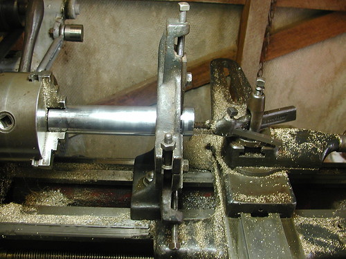
I decided to make my toolpost from the piston rod of a hydraulic cylinder. I found a few of these in the scrap bin of a local buisness that deals with just about anything to do with hydraulics and pneumatics. First, the rod is chucked and set up in the steady rest.
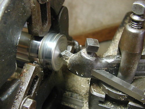
Facing the end of the rod. This rod is tougher than normal mild steel, but still machinable with HSS or cobalt tool steel, which is what I'm using here. I think it could be 4140 or something similar. It was also bent a fair bit, which is probably why it was scrapped in the first place, though there was plenty of room to machine that bend out of it.
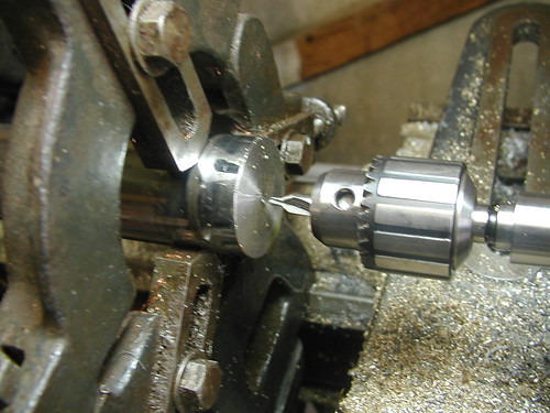
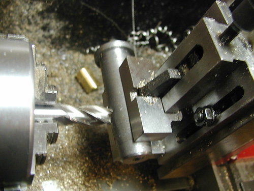
Centre drilling to take a dead centre. I'm using a dead centre because it will wobble less than my live centre mounted in a morse taper sleeve would.
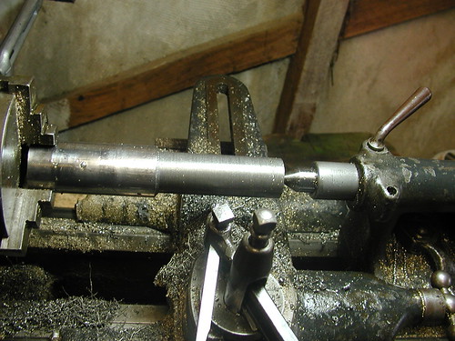
The steady rest is now removed and the tailstock is set up and wound out to support the workpiece.
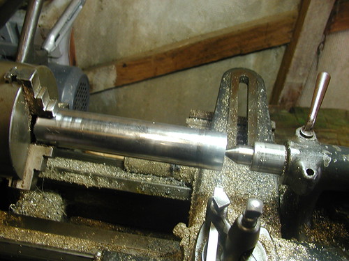
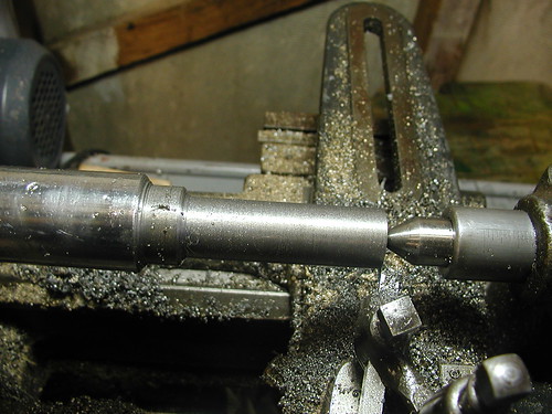
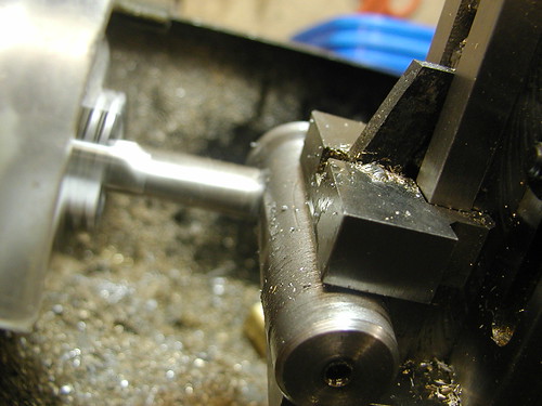
Turning the OD down to 1 3/32" which is the largest diameter. To cut this tough steel, my technique was simply to use the lightest feed and lowest belt speed except for back gear, with lots of lubrication all the way.
The result of the first turning operation. This stuff tends to cut a bit rough, but that doesn't matter in this case, since any burrs can be removed with a file.
Next, the carriage stop is attached to the bed and set to stop 5/32" before the shoulder left from the previous operation. This will make the next operation considerably easier.
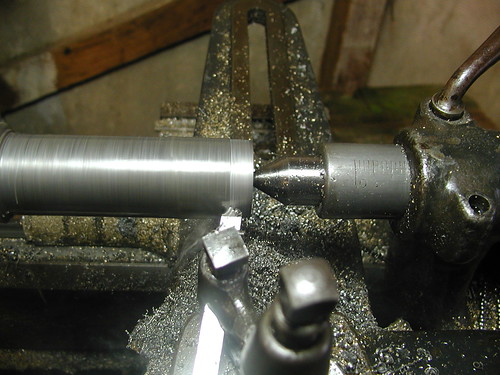
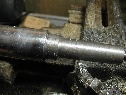
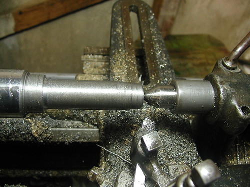
Turning the rest of the length down to 55/64" which is the diameter of the section containing the slot. The carriage stop will prevent the tool going where it's not wanted, i.e. leaving a 1 3/32" OD shoulder 5/32" thick.
Second turning operation completed. The shoulder goes back further than the 5/32" required to provide a generous cutoff allowance.
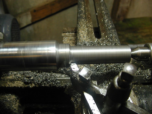
The tool is then turned around a bit to face the shoulder. I started from the outside and moved in because there is no room here for a conventional facing setup.
The result is a straight shoulder with no taper which is what I want.
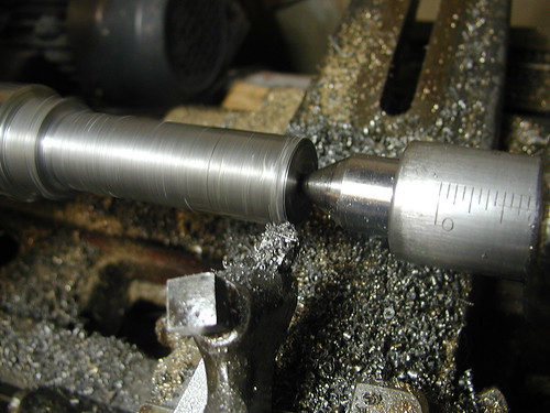
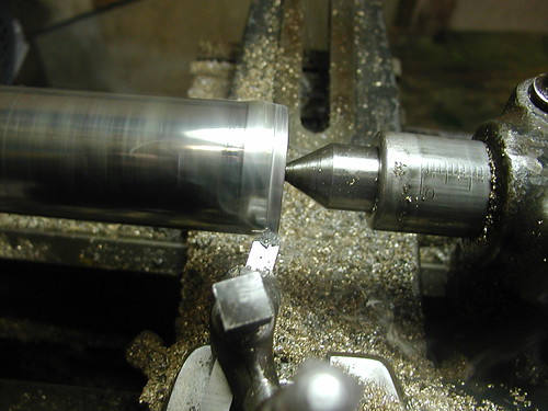
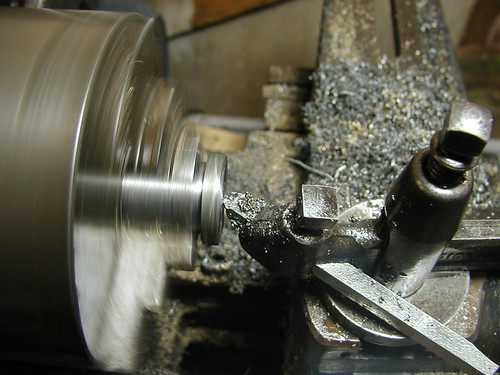
The compound slide is now set to 3 degrees to cut the taper at the end, shown in progress here. When using the compound slide in this way, there should be no need to move the carriage, only the cross slide to set cut depth and the compound slide to provide the feed.
The toolpost with the taper cut ready to be cut off the parent stock.
Facing the bottom after cutting off.
The existing toolpost is now removed to check how well the new one fits. Looking good so far.
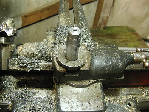
The toolpost is now clamped in the vertical slide on the Sieg to mill out the slot. A 12mm end mill is being used here to cut the full width in each pass.
Milling out the slot. It was slow going, and took two days working on and off to complete, but I got there eventually.
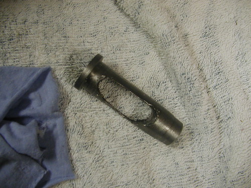
Here's the result. The slot is way off, but it does the job. This picture was taken before the top was drilled and tapped for the clamping bolt.


