80 mm copper vertical multitube boiler

Home Model Engine Machinist Forum

Help Support Home Model Engine Machinist Forum:

This site may earn a commission from merchant affiliate links, including eBay, Amazon, and others.

Henk

Well-Known Member
Joined
Mar 10, 2010
Messages
92
Reaction score
57
Hi all,

This is a limited pictorial of building a 80 mm multitube boiler. I am already quite far in the process, so when I do the writeup now, it means that I still remember the start, and the end is in sight...

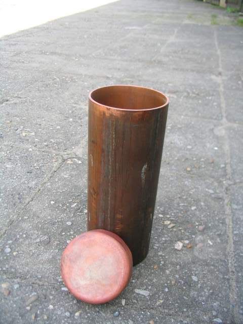
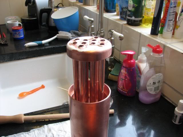
The boiler size was defined by the biggest (seamless) pipe I could locate at the scrap dealer. Wall thickness is 2 mm. Front caps are 3 mm. Volume is just under 0.5 liter.

I followed the instructions / regulations for a 6 bar, but put a 3 bar limit on the safety to steer clear of any formal testing.

There's few reasons for building:
First : I built a steam engine. Although using compressed air is very efficient, it just feels a bit like cheating.
Second: I am in the (slow) process of building a 3.5 inch locomotive. This one will definitely have a real boiler. As these are intimidatingly complicated (to me), I thought it was a good idea to have some practice.

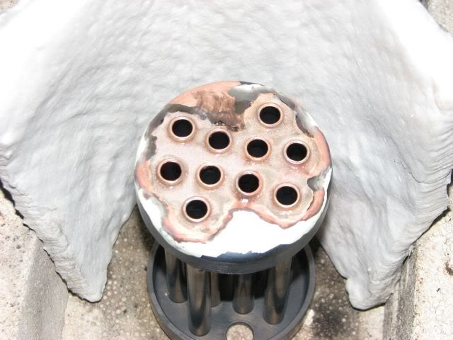
I could have chosen for 2 mm end caps, I wanted to have a feel of the consequences of 3 mm (which is what is needed for the boiler loco). The other reason is that I could find 3 mm, and not 2 mm.

Step one:
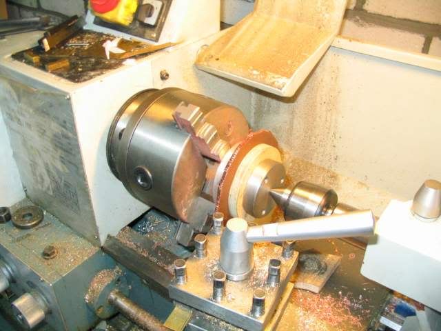
Turn tube to length. Sorry no pictures. I used a long M10 thread (with a center on the tailstock end), nuts and bolts and two MDF disks to support the barrel.

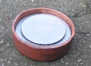
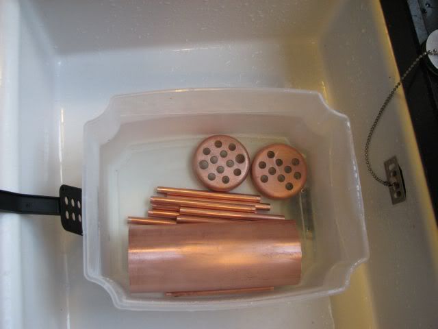
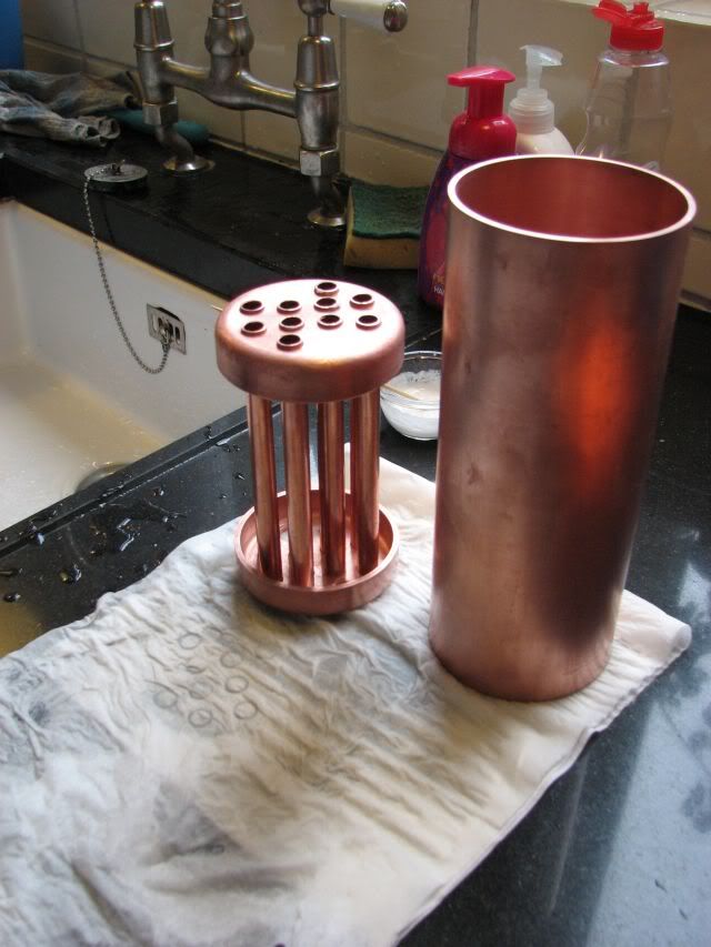
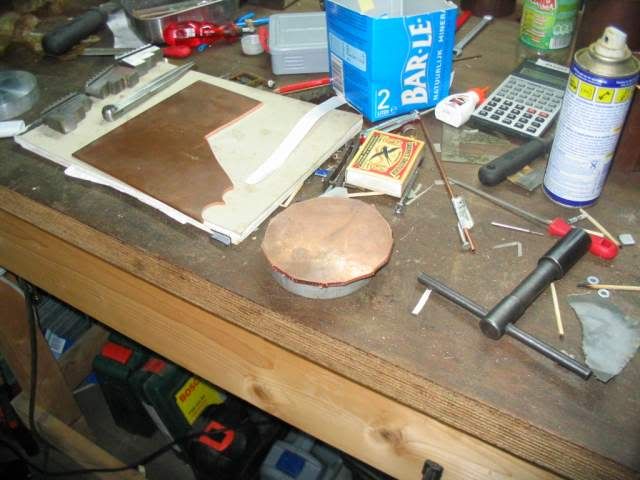
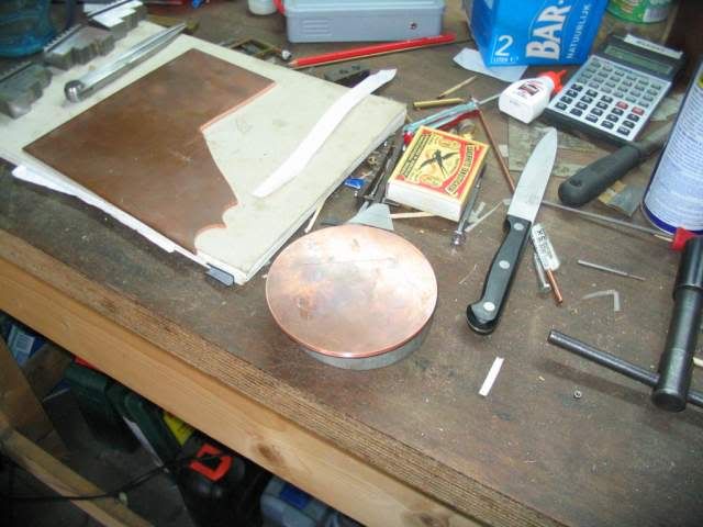
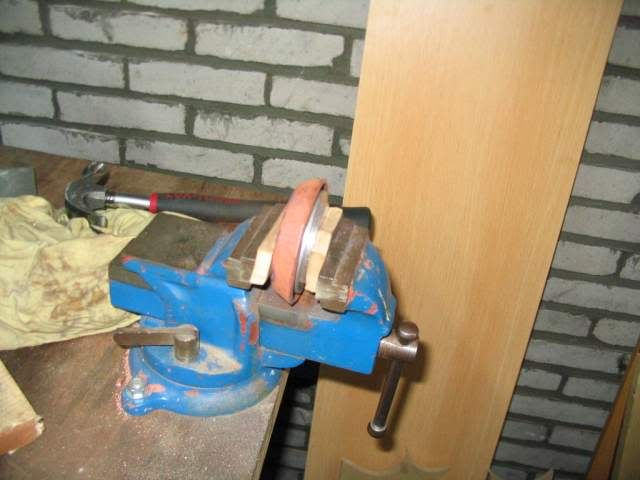
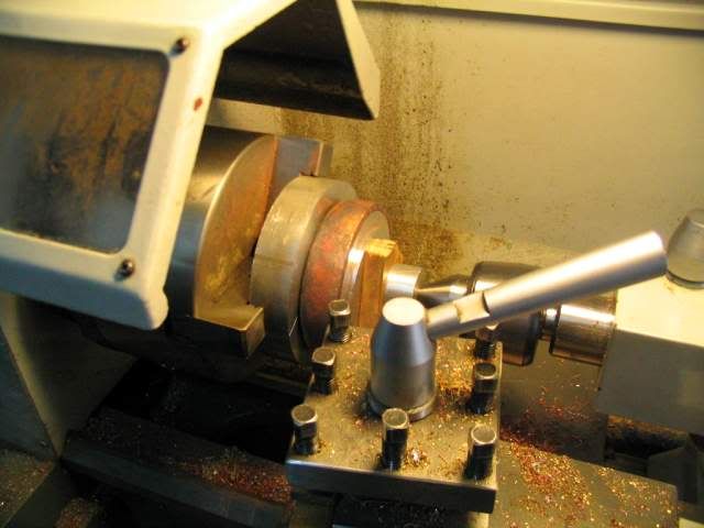
Step two: Make end caps.
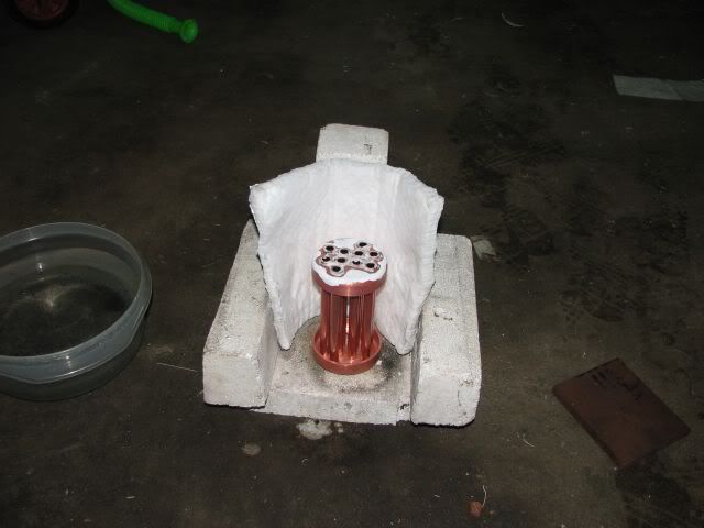
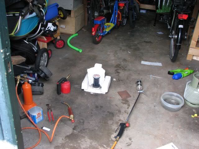
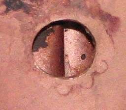
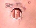
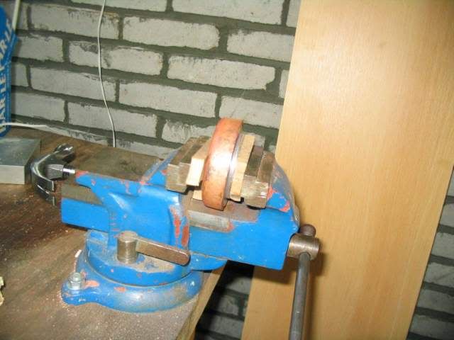
TN_ketel__015.jpg

TN_ketel__016.jpg

TN_ketel__017.jpg

Annealing
TN_ketel__018.jpg

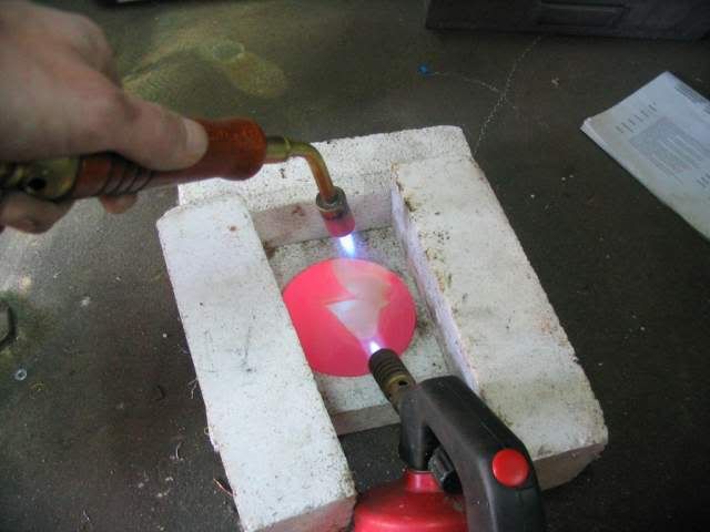
It really took a few minutes every time to get it to this temperature. Lesson: Get a bigger burner


Thanks for the thread, Henk. Don't want to get ahead of you, but what is the number and diameter of the firetubes your using? Also, how are you going to fire it?

Thx...
Chuck
 
Chuck,

BTW: I chose firetubes as opposed to watertubes as the firetubes is more like what's on a loco.

10 firetubes, 10 mm outside diameter, 1 mm wall thickness.
Arrangement :
4 on a 21 mm diameter circle,
8 on a 48 mm circle , but to allow for the safety valve and the steam exit, 2 positions are taken by threaded inserts.

I did not maximize the number of tubes. The max I could fit was 16. The 3 mm minimum distance between the tubes looked a bit small when I tried to visualize me correctly positioning a solder wire in the space between the tubes.

This arrangement (4/8) allowed me to place the inner tubes such that the distance between the tubes in the inner ring is equal to that of the inner tubes to the outside tubes. This maximized the minimum intertube distance to 5 mm. This was a distance that I was more comfortable with.

Another reason for not maximizing the firetubes is sheer risk in numbers. Everyone of the joints needs to be good...

As to your question on fuel: I am not sure yet. I do not anticipate many fire-up occasions - nor prolonged sessions. Therefor I will probably start with some simple ethanol burner (like on food hot plates). The evaporation burners seem scary to me - though I may change my mind. Once built, gas seems easy and safe. But more effort in actually building. As the main reason for doing this boiler is as a practice run, I would like to keep the fuel system easy.

Henk

 
Beating end caps to shape. This step cost a lot more time than I anticipated. Every anneal/beat step took ~ 10 minutes.

Details: template from aluminum. I used a piece of wood to placed on the copper to take the direct hit from the hammer. I assumed it is a no-no to directly hit the soft copper. If someone has info to the contrary, I am interested.

TN_ketel__019.jpg

7 beatings later
TN_ketel__026.jpg

another 8 times:
TN_ketel__034.jpg

Turning down length:
TN_ketel__036.jpg

BTW, from left to right: Chuck, aluminum plate, double sided tape, end cap, aluminum template, mdf pressure plate, aluminum pressure plate.

Now in retrospect, I think I overdid the length of the end cap. The code I used gave an optimum overlap length relative to the thickness of the plate. Now I could have used 2 mm. So also in the strength of the joint you can refer to the 2 mm I think.

Anyway, result is that I now know I can beat 3 mm Copper into the proper shape. It just takes a real effort.
 
Henk said:
Beating end caps to shape. This step cost a lot more time than I anticipated. Every anneal/beat step took ~ 10 minutes.

Details: template from aluminum. I used a piece of wood to placed on the copper to take the direct hit from the hammer. I assumed it is a no-no to directly hit the soft copper. If someone has info to the contrary, I am interested.

TN_ketel__019.jpg

7 beatings later
TN_ketel__026.jpg

another 8 times:
TN_ketel__034.jpg

Turning down length:
TN_ketel__036.jpg

BTW, from left to right: Chuck, aluminum plate, double sided tape, end cap, aluminum template, mdf pressure plate, aluminum pressure plate.

Now in retrospect, I think I overdid the length of the end cap. The code I used gave an optimum overlap length relative to the thickness of the plate. Now I could have used 2 mm. So also in the strength of the joint you can refer to the 2 mm I think.

Anyway, result is that I now know I can beat 3 mm Copper into the proper shape. It just takes a real effort.
I have used dead blow hammers, lead mallets and ball peen hammers directly on the copper with no problems.
Regards,
Gerald.
 
Gerald,

Thanks for the info. I had to look up "peen hammer" though. As I own none of the mentioned hammers, I will have to expand my tool set.

BTW, I forgot to show the first end cap. It was definitely too oversized. As a result I had to drill/tap a threaded hole to be able to remove the mandrill.
TN_ketel__013.jpg
TN_ketel__012.jpg


All boiler parts being pickled.
ketel_001s.jpg

This was the first time I used citric acid. Before this I used phosphoric acid from drain deblocker (for lack of a better word). It also worked, but reading about the less aggressive nature, I thought I'd try out citric acid for a change. It may be a bit slower, but that is not necessarily bad. Though I did not solder the main tube yet, I threw it in to get it nicely clean. You may seen that I reduced the size of the pipes with 0.2 mm to ease the building process prior to soldering.

Trial assembled internals. It starts to look like a boiler now.
ketel_002s.jpg


Assembly prior to soldering, flux applied. First I wanted to solder one end cap with tubes. The main boiler barrel is now only in use as a fixture. This is also the first time I used correction fluid to limit the soldering area. One of the reasons for doing small steps is that I wanted to have a good chance of seam inspection.
ketel_003s.jpg


Now at the soldering setup, with rings of solder around each tube:
ketel_004s.jpg


ketel_009s.jpg

Soldering went pretty easy. I was very glad with the huge burner I got. I think it is rated at 51 kW. Lots. Scary. But usefull. My guess is that it is even more fuel efficient than a smaller burner, as it doesn't take so long to heat up the whole boiler. I can also recommend the heat shield (local DYI store, 10EUR). The stones hardly got hot.

After soldering. Looked good to me.
ketel_007s.jpg


So I was wrong. It looked good. But it wasn't. Only 4 of the tubes were really well attached. 5 were not done at all. One was partially done - the one on the right on this picture.
ketel_010s.jpg


What happened is that I countersunk each of the holes. However, still a tiny ridge was present on the outside of each hole. And the diameter of the solder (1.5 mm) was such that the solder rested just outside of this ridge. So the end result was that there was a nice liquid pool of solder flooding the top surface, but it could not get over these ridges. On an unrelated note: I think the correction fluid did its job.

So I paid more attention to deburring in the next run, of which the result can be seen below. Also closer inspectin shoed that all joints are now well connected.
ketel_011s.jpg

 
Now onto the top cap. Assembly was easier than I had expected.
I did not use the solder rings due to the bad results I had the first time - although the better deburring should have helped. Now I just put the soldering wire to each tube when hot. I did worry that I would plain forget one of the twelve positions.
ketel_013s.jpg


Luckily no problem. Close inspection also showed each joint showing solder on both sides.
Inner boiler and main barrel in which I put the holes for the water level / pressure/ water inlet. BTW: this boiler was also the first time I use a step drill. I found it to be very convenient not having to change drills - I liked it a lot. Now the total looks like this:
ketel_016a.jpg
 
Henk,

That boiler is coming along very well indeed.

As a helpful hint, just a slight change to your flame position would have given you good results first time.

With the rings around the tubes on top, if you had heated the flanged plate from underneath, it would have ensured that the materials to be joined were up to temperature before the solder began to flow, and as you most probably well know, the solder flows towards the heat source.

When doing the flanges to the main tube, you really need two burners if at all possible, one playing around the outside of the boiler tube to get it up to temperature, and a secondary one playing on the inside of the boiler tube onto the outer edges of the flange. Get the tube up to temp first, then when you see the solder moving, bring in the secondary to control the solder flow, still keeping the larger burner playing on the outside of the tube.

If you only have one heat source, get the tube up to temp first, then transfer the heat to the inside to get the flow going, and hope that the tube doesn't lose too much heat.

I am not trying to tell you how to do the job, that is up to you. I am just giving you general pointers on how I got very good results when making my own boilers, and I have made a fair few of these firetube boilers over the years.


John
 
I have been a pipe fitter for 42 years and have always brushed the pipe joints with silver solder paste then heated the areas to be soldered using wire or sticks of silver solder. This ensures that the flux draws in the silver solder paste first then the silver solder wire second.
It also makes less of a mess to clean off the tubes.
Kind regards,
Giovanni
 
John,

Thanks for the help that I implicitly needed. I will most probably (hopefully) not be able to use it on this boiler though. I did the flanges to the main tube yesterday before I read your post. More on that later. But I will give it a go next time. I was on my own when I did this, so admittedly the thought of trying to use two burners at the same time seems a bit challenging -specifically when both of them are connected with a hose.

Dale,
Yes the correction fluid is supposed stop the flow. I undoubtedly read about that here in HMEM. It is all I know about it, and it sounded logical. And I indeed had the impression it worked. So my best advice is to simply try it.

Giovanni,
I am not sure I understand you correctly. It seems you are suggesting that the solder can be used to heat the part? And you are mentioning flux, silver solder paste and silver solder? Could this be a mxup between low temp silver solder (melting temp say 220 deg C) and high temp silver solder (melting temp say 640 degC)?
 
So as said, I did the flanges to the main barrel next. All fluxed up and with small pieces of solder distributed evenly.
main_tube_002s.jpg


I also fluxed the top part. My plans was to first do the bottom part, and while hot have a look whether the top side (which is located on the bottom during the first part of this run) still looked fluxed up. If so, I would continue with the top part. If not, I'd acid clean and retry.

During soldering of the top part noticed sudden movement of the inner part relative to the outside. I did not use any pins to keep things aligned. And I should have. I reckoned there was enough tension to keep things in place. And of course what happend is that the main tube expanded when it got hot, before the center part did. And the inner part stood out. The main barrel dropped a few mm. The result was that the flanged top plate now partially blocks the hole for the pressure gauge/ water gauge.

At the end of doing the bottom part I turned the boiler. Top part looked good enough to try some solder, which I applied after reheating. This is how it looked afterward. The good news is that this error allowed me to clearly see the joint from the inside. It looked good.
main_tube_003s.jpg

 
It does seem that I take two steps forward and one backwards. But a least so far it still feels I am getting somewhere. At this point I had a choice between reheating and trying to move the inner part upwards relative to the main tube, or remove the offensive part from the holes. I choose to do the latter as I did not like the risks involved.

1) Just depending on gravity did not sound OK. What could happen is that only one of the end caps would move and come loose from the firetubes.
2) I also didn't know whether the full end cap could come loose, and then maybe the solder would not want to blend together anymore (I did have this on low temp solder with not very clean surfaces).
3) General observation: at least half of the times I want to do action A, also an unwanted side effect B happens.

On the other hand removing a part of the flange also reduced the strength a bit. However both the thickness is larger than needed, and the overlap is. Required overlap is 3-4 times cap thickness. I used 4 times, cap thickness is 3 mm. Therefor there is at least a 3 mm margin. And this is also the amount I need to remove.
 
Henk,

Don't worry about it, just redrill out the hole, or better still, file it out. Then get as much of the swarf as you can out of the boiler while you still have large holes to work thru.

I wouldn't worry too much about removing some of the flange. I have some plans by ET Westbury, and they show end plates silver soldered into the end of the tube with no flanges on at all, just good fillets. What we do nowadays is all geared towards over engineering, which isn't a bad thing when it comes to something like boilers and rechargeable gas tanks.


John
 
John,

thanks for the confirmation. I almost did what you proposed (again your advice and my execution were happening on the same day). So one of the things I learned is maybe to put a day between writeup and the next step.

I made at least one mistake. I used an endmill (10 mm). My reasoning was that for filing I would only have a very small stroke due to the fire tubes. And for drilling, there would only be a very small part of the drill being located in the original hole, and a large force trying to push the drill sideways. And smaller mistake: The setup I used was not sufficiently good I think in hindsight. In particular, the movement in y (or rather rocking back and forth of the tube) was noticeable.
main_tube_004s.jpg

And though I tried to locate the original hole OK-ish (I used a 10 mm shaft in the spindle and moved the table until it could enter without noticeably touching the hole), the end result was a very eggshaped hole. The horizontal size is close to 11 mm.
main_tube_005s.jpg
main_tube_005zoom.jpg

So as a repair, I now reverted to boring. Second time I bored on the mill, first time was to make the 12 mm holes for the top cap steam and safety bushings. This worked OK, although the picture the difference does not really show a big difference.
main_tube_006zoom.jpg


For the second hole, I put a bit more effort in locating the hole (with DTI) and bored from the start. In order to make a nice round hole, I did have to increase the diameter by 0.25 mm. This meant I had to redo two of the bushings I already made, but that was no big deal.

I just also soldered these onto the boiler (pictures tomorrow). Nothing untoward seems to have happened. The boiler is now in the pickle.
 
Henk,
I use hi-temp silver solder paste,flux and silver solder wire or stick.
The silver solder is purchased in a syringe and is sold through jewelry supplies.
It also makes cleanup much easier if you can use it without the silver solder wire.
Regards,
Giovanni

untitled-5.png


http://www.ishor.com/Solders.php
 
Henk said:
3) General observation: at least half of the times I want to do action A, also an unwanted side effect B happens.

This is going well Henk and I've got to agree with your observation. I've been chasing leaks in my boiler on and off and now only have 3 minor leaks. I need to pluck up courage, go to it again, and deal with them but in the back of my mind is your point 3.

Going back to soldering the tubes, one of the experts books advises putting small V nicks with a file in the tube holes. The solder flows freely through nick to the other side. I did one end of mine and forgot the other. The difference in how it soldered was very noticeable

Pete
 
Back
Top