302 Ford V8 in 1/3 scale

Home Model Engine Machinist Forum

Help Support Home Model Engine Machinist Forum:

This site may earn a commission from merchant affiliate links, including eBay, Amazon, and others.

gbritnell

Project of the Month Winner!!!
Project of the Month Winner
Joined
Jul 16, 2007
Messages
2,979
Reaction score
1,046
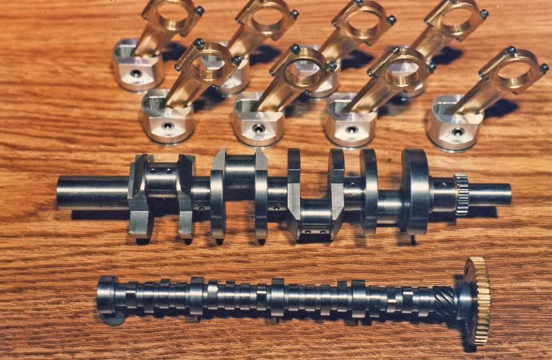
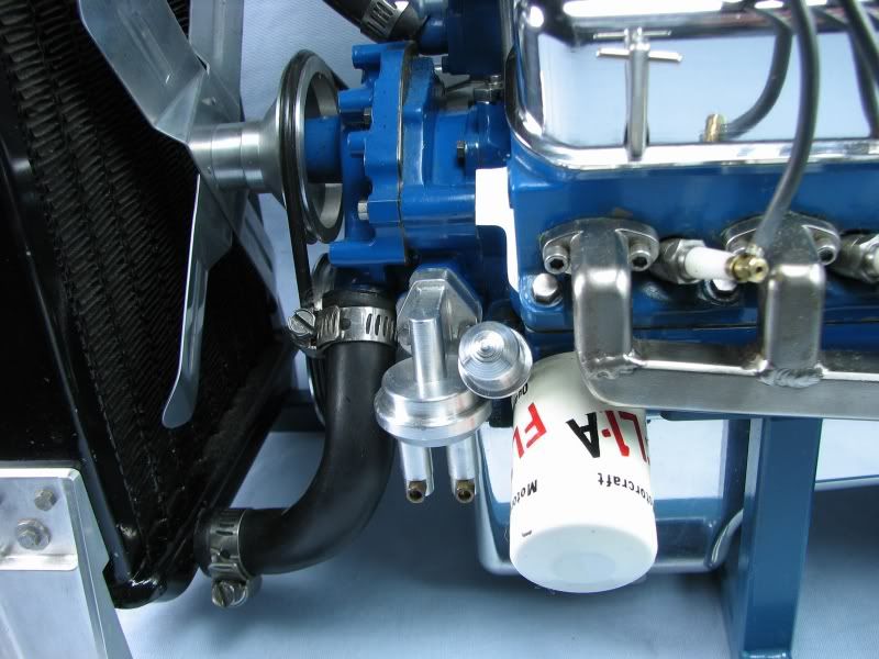
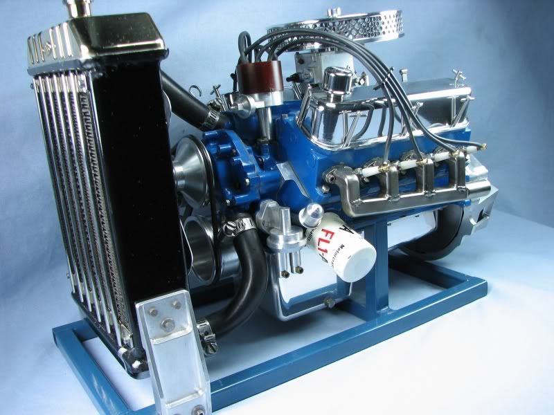
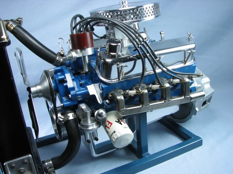
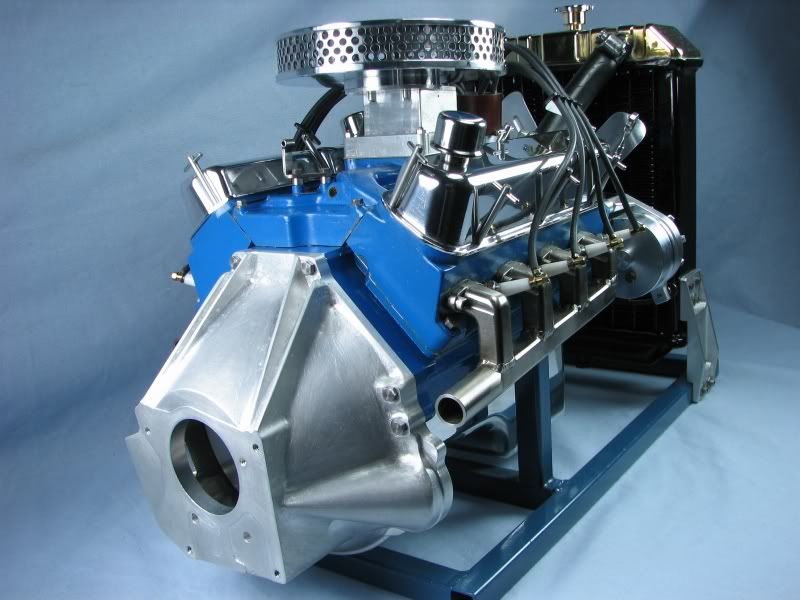
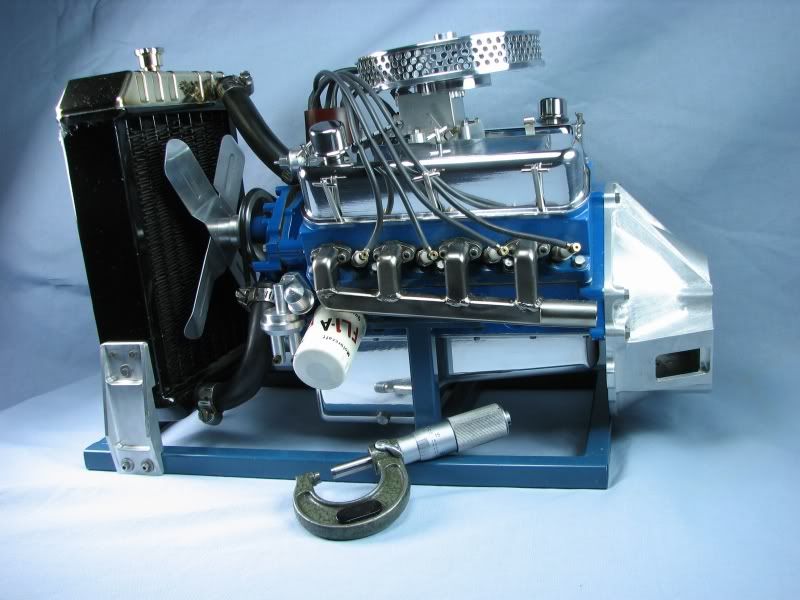
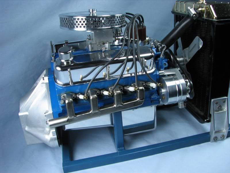
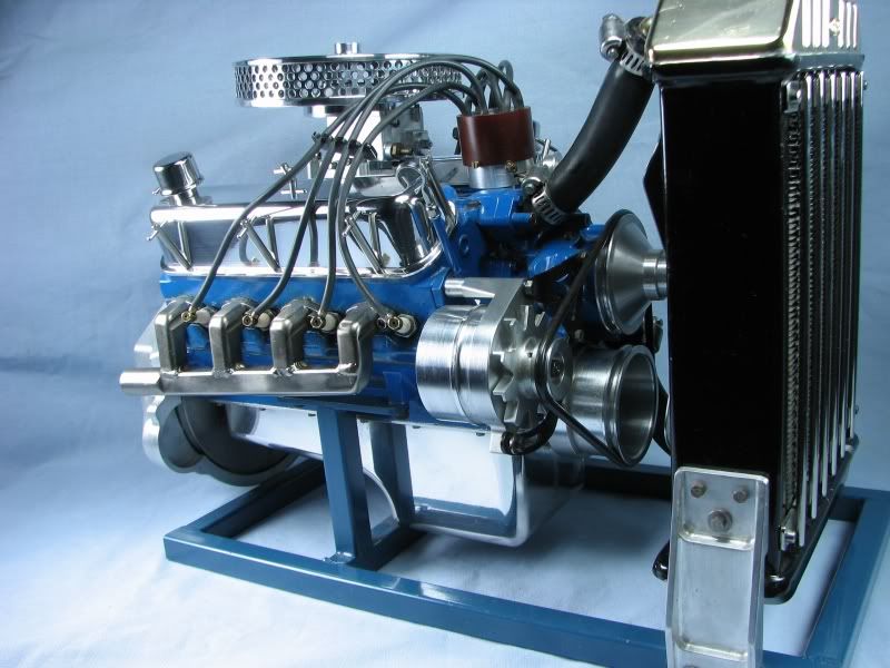
I was going back through all the old threads I started since joining this forum and realized that I hadn't posted my 302 Ford engine other than to answer someone's question about plans for a V8. The first series of photos are of the block, heads, cam and crank and disassembled on my workbench. First I will give you some background on this build. I first got into gas engines by building hit and miss engines from castings. After seeing some of the multi cylinder engines being built I designed and built my 4 cylinder OHV engine. At the time (mid 80's) I was working for the Ford Motor Company as a metal patternmaker. At the foundry where I worked we made iron castings for the 302 V8 engine. These were the block, heads, intake manifold, exhaust manifolds and water pump. Working in the pattern shop gave me access to the engineering drawings and when word surfaced that the 302 would be phased out I decided to build one. I decided on a scale (3:1) and started making sketches and drawings to create it. This would be a scratch built engine as the process for making castings is quite an undertaking in itself and with the plan to only build one I really didn't need all the extra work. Starting with the block it is made from 6061 aluminum. It has iron sleeves and has a complete water jacket machined into it. This was accomplished by machining out the jacket area and making a head plate to seal everything up. I had good luck doing this on my 4 cylinder so this was the direction I took with the V8. I don't have the amount of time involved in each component but the entire build took over 3 years and approximately 2500 hours. Most of this was because of the extensive hand machining to make all the parts look like the castings.
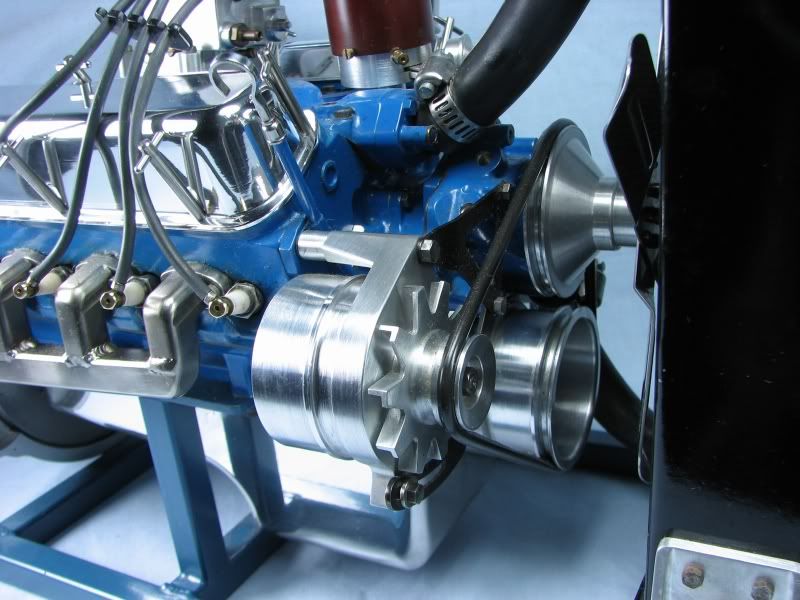
The only pictures I have of the individual components were taken with a film camera as digital wasn't around at that time, at least not for home use. The front picture of the block shows a boss to the left and above the crank bore. This is for an idler gear to drive the cam. The cam design would be the same as the full sized engine because it was driven by a cam chain so with the intermediate gear both the crank and cam would turn in the same direction.

302FORDBLK2.jpg


302FORDBLK1.jpg


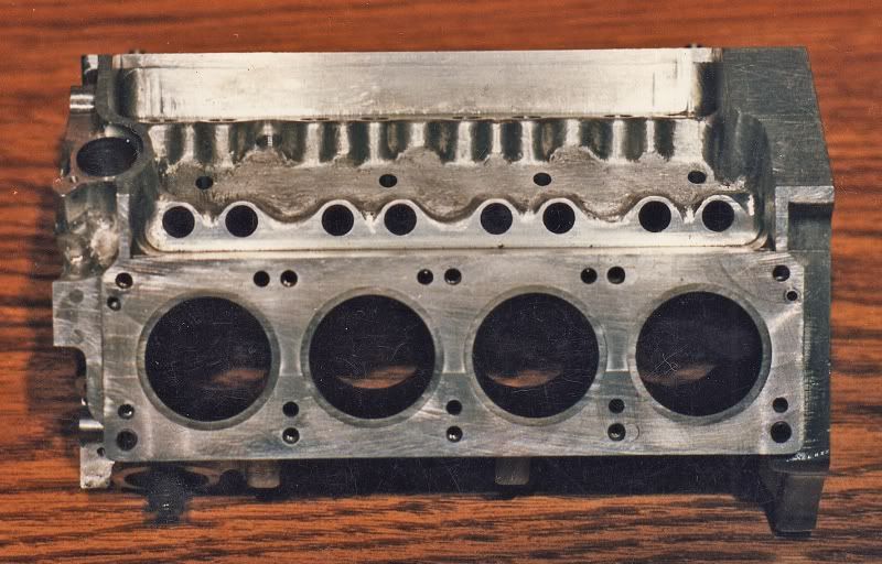
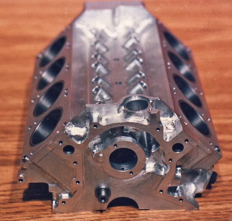
The block has full oil passages drilled into it and is pressurized by a gear pump as on the full sized engine.
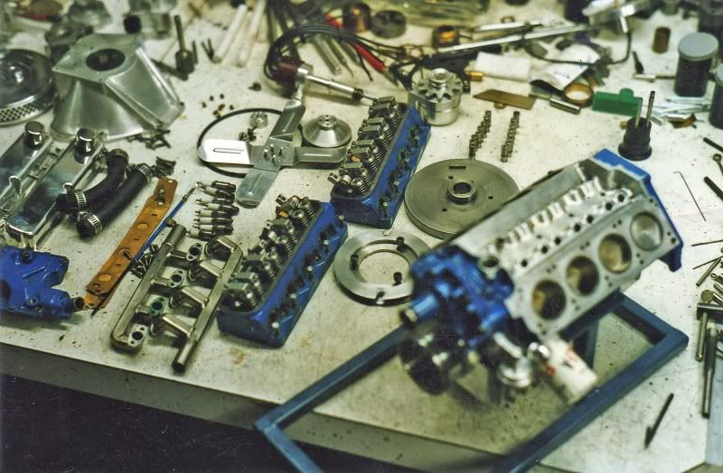
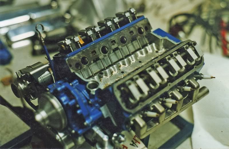
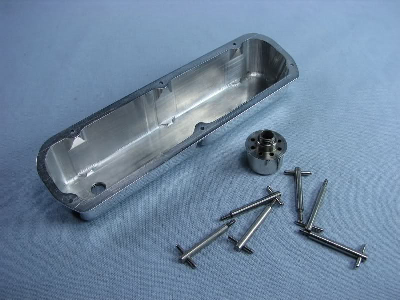
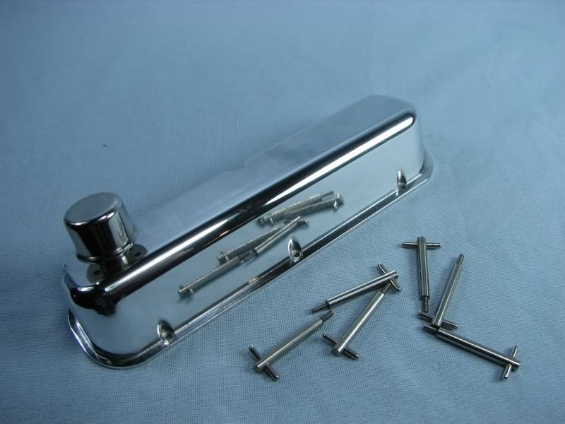
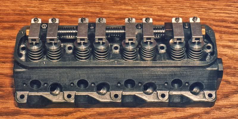
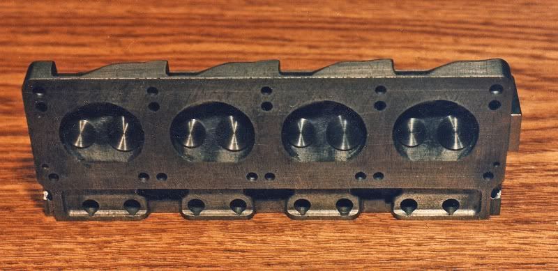
Next comes the heads. They were machined from Durabar or schedule 40 continuous cast iron. This material machines great and when drilling will sometimes give a curl as when machining steel. The main reason for using iron is it eliminates having to put some other material in the head for valve seats. To produce the water passages in the head I layed out an end view of the head with all the porting, head bolts and pushrod holes. The remaining spaces were used to drill passages lenthwise through the head. The steam holes from the block were then drilled up into these passages. The pushrod holes provided a challenge as the full sized heads have a boss cast into the port to provide a wall around the hole. With my ports being round instead of rectangular this became more of a problem. To accomplish what I needed to do I first drilled my ports in and then reamed the pushrod holes oversize to use sleeves in them. The 2 pictures show the rocker side with the exhaust ports and spark plug holes and the combustion chamber side with the holes for the pushrods, head bolts and steam openings.

302FORDHEAD2.jpg


302FORDHEAD1.jpg


That's about it for this posting. I don't want to have a problem and lose everything that I've done till now.
gbritnell

 
Next comes the crank and camshaft. The crank is iron also. It was machined close to size and then the journals were ground with a toolpost grinder on my lathe. The crank is drilled from the mains to the throws for oil distribution. The cam is made from drill rod (silver steel) unhardened. I used the method for producing the lobes like I do for all of my engines. Without getting to wordy about it I make a stepoff chart and machine them in my rotary table. The facets are then filed up by hand and everything is polished. I've had good luck with this method so this is what I use. The only design problem I had with the cam was how to drive the distributor/oil pump similar to full sized practice. I purchased 2 helical gears for this job. The one on the cam is put in place by drilling and reaming the end of the cam, making a stub shaft with the front journal on it, pressing it into the gear and then pressing it into the end of the cam and pinning it in place. Having grown up in the Hot Rod era (late 50's-early 60's) I worked on many engines and never once paid attention to the fact that the gear on the cam and the gear on the distributor are different diameters, but they turn at the same speed. This is accomplished by using different helix angles on each gear but still having the same number of teeth. I couldn't get gears like that so I used 2 of the same helix angle. To make them work I changed the centerline of my distributor just enough to fit the available gears. To drive the oil pump from the distributor I threaded the end of the shaft and then took 2 socket head set screws and mounted them one on top of the other. The outermost screw was ground down until the hex socket broke through and then I kept fitting and grinding until it lined up with the bottom screw. This method provided me with a way to drive the oil pump with a hex shaft made from an Allen wrench. I can remove the distributor if needed and then replace it by turning it until the hex engages and then mesh the gear to set the timing. The rods and pistons that you see in the picture were changed after completing the engine because the single ring pistons didn't seal well enough so I made another set with 3 rings, 2 compression and 1 oil ring. The rods are made from bearing bronze. The crank bearings are split shells made from the same material. Being as the engine is pressure oiled I didn't forsee any lubrication or excess wear problems.

302FORDCAMCRNK.jpg


The next picture is with the engine torn down on my workbench after a blown head
gasket. I have tried many materials for head gaskets, annealed copper sheet, high temp fiber paper, teflon and a few other things that I had laying around. The .005 annealed copper sheet with a thin layer of high temp silicon sealer seems to work the best.

302FORDAPART.jpg


302FORDAPART1.jpg


Ok, I'll end this one now to be safe.
More to come.
gbritnell
 
Thanks for the photos gbritnell. I don't remember seeing this engine when I stopped by to say hi in Toledo, but I could have easily missed it. Such was the abundance of eye candy at the show.

Cheers,
Phil
 
Here we go with the next chapter, the intake manifold. I'm sorry I don't have any construction pictures of the remaining components but like I said at the time the only thing I had available was film and it was too much work to take pictures and get them developed to see what I had before moving on. I will describe the construction of some of the other parts and then post pictures of the complete engine. The intake manifold was made from 2 pieces of brass sheet. I cut them to size and layed out the intake runners and water crossovers in them and cut them with a ball mill. The 2 pieces are split at 45 degrees near the port face to provide a solid surface at the ports. When I had the inside machined I cut a piece of sheet silver solder to match the profile of the port runners and water passages at the ends of the manifold. Everything was fluxed and clamped together and heated up with a torch until the solder visibly flowed out of the joint line. People have asked me what part was the hardest to make on the engine and I tell them the intake manifold. After soldering the ports were capped off and pressure tested to make sure they didn't leak before moving on. As luck would have it everything was good. Now the outside got layed out and the hand machining started to whittle away everything to make it look like a casting. The manifold moved from milling vise to rotary table any number of times to complete the runner shapes on the outside. This picture gives a pretty good shot of the shapes in the manifold.

302c.jpg


The exhaust manifolds were fabricated from stainless steel. I machined all of the bend pieces out of one piece of stock. The exit tubes were left as long as the longest piece. A runner was made out of a piece of round stock, drilled and the outside squared up to match the dimension on the elbow pieces. The individual elbow pieces were then screwed to a fixture plate and the angle of the runner tube was milled onto the end of them. That is why the were all left to the full length to begin with. After milling and deburring the runner was clamped in place and the whole thing was TIG welded together. If anyone has welded stainless steel it loves to warp and the manifolds were no different. They seemed ok. on the fixture but when I started to take the bolts out the end ones were very tight. After removing them I found that it had warped in somewhat of an arc. The port face was almost flat but it had a bow from end to end. I don't remember how much but I had to elongate the end holes and grind a little in the ports to match the head port. After all the work I wasn't about to try another method. At times during the construction I would get burned out and just leave everything, sometimes for several weeks. I really began to wonder if I would ever get through this project. You have to understand that I only had a 9" Southbend lathe, a 6" Atlas/Craftsman lathe and an Enco mill drill to work with. I'm not complaining as many others don't even have these I just want you to know that you don't need sophisticated tools to do something like this. The only outside tools I used was a knee mill to line bore the crank and cam holes. Here's a closeup of the exhaust manifolds.

302f.jpg


gbritnell

 
The water pump body is made from aluminum. It has a stainless impeller and shaft in it. The back of the shaft is supported by a bronze bushing and the front or drive side has a stainless ball bearing in it. Again this was painstakingly cut by hand to resemble it's cast big brother. The water is pumped through the block, up into the heads, into the intake manifold through the crossover runners and out of the thermostat housing. I tried several different methods to make the radiator but didn't have much luck. It needed to be much bigger than the 4 cylinder engine and I didn't think the method I used for that one would work on the V8. I ended up taking the finished engine to the local radiator shop and being as they were 'car guys', the owner told me that they could get core material in many different sizes and to just tell him what I needed and they would come as close as possible. A week later I got my copper radiator with end plates. I needed to trim them down and make the tanks. I made up a die and tried to form the tanks. They did form but with quite a few wrinkles in them. I took the best one and used it for the bottom and ended up machining the top one from a solid piece of brass, why not, the rest of the engine is from billet. Here's a distant shot of the radiator.

302h.jpg


The distributor has a small set of points in it. I tried to make the distributor close to scale but found out afterward that in trying to keep it small I couldn't quite get enough lift on the cam to open the points effectively. It's one of those things that I'll get to one of these days.

302u.jpg


The rocker covers, air cleaner cover and oil pan are also cut from solid stock. To make the peripheral components that I didn't have drawing for I measured everything from a full sized engine and made my own sketches and drawings.

302a.jpg


302b.jpg


gbritnell


That is really beautiful!

Got any sights and sounds?
 
The bell housing was taken from a later model engine. The earlier ones were iron and didn't look like this one. This one has the stiffening ribs and makes it look more mechanical.

302p.jpg


The alternator is non-functioning other than the fact it tightens the belt to run the water pump. It has 2 ball bearings in it so no lubrication is necessary.
The spark plugs are made like the drawing that I posted in another thread. They have Teflon insulators and work fairly well. At the time the engine was built there were no aftermarket plugs available and when I made mine I tapped the holes 1/4-28. Now that Rimfire makes very nice plugs I can't use them because they're 1/4-32.
I really don't want to make another set of heads just to suit the spark plugs.

302l.jpg


gbritnell


In conclusion here's a few more pictures and the status of the engine at present. The engine will start and run slow quite well. It doesn't like to rev up with the carb that's on it. Some fellows use 2 stroke pumper carbs on their engines with great success. After I start the engine I can coax the rpm up by fiddling with the carb at which point it runs out of spark or better yet runs out of point action as I had described earlier. It needs to have a larger distributor made and possibly a Hall effect pickup on it. That should fix the ignition side of it. I definitely would like to have it running better but somewhere along the line I got a little burned out and moved onto other projects like my Holt engine. I keep promising myself that I'll get back to it, maybe this fall when I get back into the shop more. I do have several videos taken of it running but these were done with an early 90's movie camera with the little cassettes in them. I need to have them converted to a digital format.

302e.jpg


302m.jpg


302k.jpg


gbritnell

 
gbritnell,

1/3 scale didn't mean a lot until I spotted the drill chuck key in one of the photos - WOW. :bow: :bow: :bow:

Best Regards
Bob
 
Masterful work, Gbritnell. I can only imagine the patience it took to create such a wonderful piece of art. My hat's off to a master of these black arts.

Steve
 
Ohh thats luverly. We've got to hear it running. Please do a video,pleeease.

Mo :bow:
 
I think Cedge says it best...."Masterful" Thanks for such and inspiring post...great pictures too!!

Bill
 
Wow, this just totally blew my mind. That is unbelievable. Being a Ford guy I am especially blown away by it. Thank you for sharing it.
 
The oil filter, how in the world did you manage it?

Beautiful job. I think I'll mothball my shop and go play tiddlely winks. :big: :big: :big:

Ron
 
The oil filter is made from brass. It is 2 pieces, the outer shell and the top piece which has the threads and oil ports. These were silver soldered together. Naturally with having to use heat to solder it there is no filtering material inside but the oil doesn't get that dirty. The graphics were done with rub-on letters. They are available at art and hobby stores. After painting and lettering the whole thing was clear coated. The oil from the pump does flow through the filter and then into the main oil galley. The filter has an 'O' ring for a seal up against the block.
gbritnell
 
gbritnell,
Holy S.....! You are amazing, that is absolutely beeee uuuuu ti ful. I had dreams of grander on building a 1/6 scale 427. The worst thing I did was to buy a die cast pre built model for $20. I keep on the shelf next to my other engines. And I dream and dream and.....
My hats off to ya :bow: :bow: :bow:
Tony
 

Latest posts

Back
Top