3" multitube - my first

Home Model Engine Machinist Forum

Help Support Home Model Engine Machinist Forum:

This site may earn a commission from merchant affiliate links, including eBay, Amazon, and others.

DavidP

Member
Joined
May 31, 2010
Messages
20
Reaction score
0
Let me introduce myself. I have been lurking here for about a month reviewing the boiler builds and like a few things about the people. Not least is the large Australian population familiar with the AMBSC codes.
I now have two stationary engines under my belt and have no formal training so have a lot of skills to gain yet (I, like many here am ex-service - Royal Australian Infantry. Regular for my first career and still an active reservist) Which leads to my problem. I have visited two clubs and had a pretty warm welcome - I was really well treated in Melbourne at Easter with a full tour around the facilities with my younger son (if you want a warm welcome, just bring an interested young kid) My only time for the hobby is irregular nights and I feel I would have little time at the moment to contribute to a club - priority is getting the kids through high school.

I have decided to try my first boiler by opening up to comment. Plans are drawn from the Harris book with mods to get the fittings in.

??? how do I get a picture in here ???

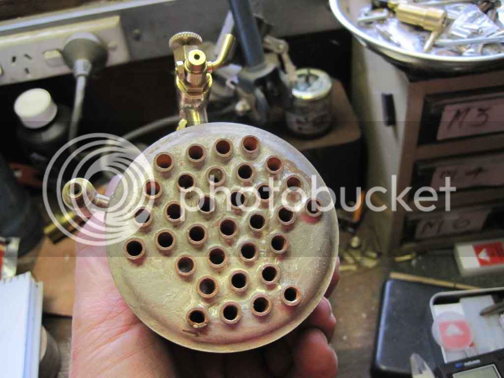
reconciling the Harris drawing with the AMBSC code, i need to drop four of the tubes to get bushes into the top tube plate for the safety valve and steam pipe. The reason is that the code specifies 9mm for the bush and 3mm for the web in the tube plate. I therefore have to drop two edge tubes and move the centre out a bi to get the necessary web. is this normal?

I can fit the other bushes into the side wall utilising the extra space provided by the flat side of the hex tube layout.

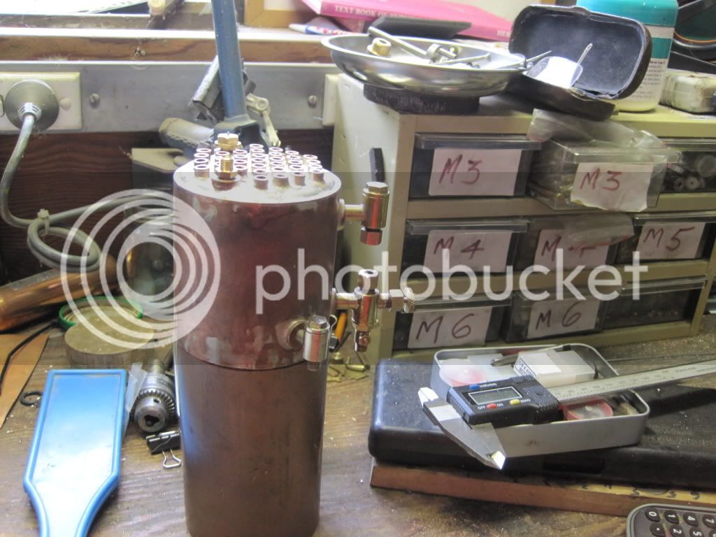
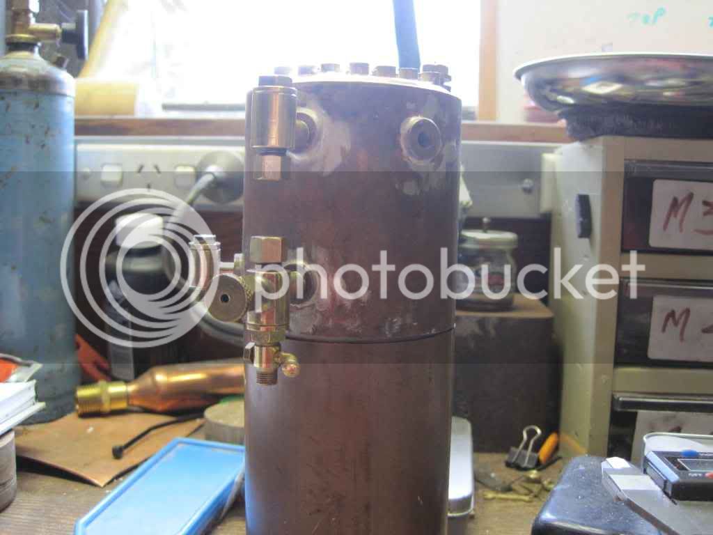
I plan on separating the two top bushes by 120 deg and creating 'buttresses' in the smokebox shape to improve the flat area on top for the fittings.

All sizes as per code, just waiting for stuff to turn up from Melbourne.

If the copper doesn't turn up this week, i will start on the fittings. Not done these before, so have been culling this site for approaches. is any one able to point me at a set of drawings for fittings suitable for this size boiler? (valves, pump, and watertube).

look forward to any feed back you can provide - first how to get a picture up so I can post the plans.

Dave

View attachment Multitube plan 1.pdf
 
first of all welcome.
As far as club involvement I would suggest communicate and ask question to the club members and express your concerns . Try to feel out the club culture. I will say I am far from being an expert I know of no HSM clubs close enough to me to be involved in. I have been involved in one club that shuns you if you do not attend monthly meetings and they have mandatory attendance to at least one work day a year or pay a fine. The president has been president forever and is a virtual dictator. Needless to say did not stay long.
I would hope that the HSM folks would understand you have a life and kids to raise and welcome you as you can make it.
as far as posting photos the best way is open an account with a hosting site such as photo bucket or one of the others. upload the photos to your account at tat site then post a img link to the thread.
for example if I copy this image location from littlemachineshop.com it looks like this
http://littlemachineshop.com/Products/Images/480/480.3135.jpg
but if I highlight the link and click on the imig icon third from the left it looks like this.

480.3135.jpg

Hope this helps
Tin
 
Dave,

Welcome to our forum. wEc1

To load your own pictures you need to join a free hosting service such as Photobucket. When you copy your images to your folder on such a site each image has a code...............e.g.

http://i389.photobucket.com/albums/oo340/Maryak/tombstone-1.jpg Then like Tin said place this code inside the image icon after highlighting the icon with one click.

tombstone-1.jpg


Hope that helps

I'm guessing your in Melbourne Vic, it helps us all if you place a general location in your profile.

Best Regards
Bob
 
Dave

I'm also a new member to a local club which has a whole bunch of great guys as members. They've just celebrated their 50th anniversary and the collective experience of the group is unbelievable. However we only get together once a month and HMES convene 24x7.

And that's the point; you have a problem to solve and overnight, if not quicker, you get an answer. As you'll see from the topics my first boiler started in March, after reading through Firebirds thread. I'm now on my second. The support of this group will keep you going, and there is no such thing as a dumb question.

enjoy the journey

Pete
 
All,

Loggin in on my son's account (thats the one on the home PC) so thanks for the prompt replys.

Actually, I'm in Canberra. Have visited running days both here and in Melb - good welcome within the limits of a busy day - and when I finish my current posting hope to get engaged. I am very close to a Vietnam vets workshop where my 84 yr old mentor hangs out. My preference is to return some community service and get involved with that - its just that they dont seem to know about boilers.

Starting the tube plates tomorrow - ready or not!
 
After some pause (lots of Reserve time, trip to a band festival in Dubbo etc) Ive done a bit.

First something to bash with:
Mallet.jpg

Then the usual forming:
FormingTubePlates.jpg

Drilling the plate:
DrillingTubeplate.jpg

A test fit (Tube is not cut to length yet):
Tubeplatetestfit.jpg

Finished tubeplates out of the pickle tonight:
DrilledTubeplates.jpg


I have made the bushes for the top - steam at 1/4 *40tpi and safety at 5/16 *32tpi to match a bought safety valve.

That leaves inlet, water tube, pressure gauge. I understand that the pressure gauge can be 1/4, but not sure about the rest - so far haven't found plans for fittings I can do at this scale. I rather like the fittings on the Shand fire engine in Model Engineer, except I'm not really confident in those tapered plug valves. I do like the water tube fittings on the Cochran thread here - nice compact design but understand that at least the bottom one should have a drain. (have an idea for that by replacing the bottom plug with a small spigot and valve.

So the plan is to do the fittings first, see what size bush they need, and then procede with the boiler.

have fun
Dave
 
Gday dave, its an interesting journey isnt it? Ive been down it myself recently, learning the ropes in the Aussie system. Which codes are you using? The 75 mm thing can go either way, I'm going small and using the sub mini codes at 75mm but less than 1 litre capacity.

Looking forward to your progress.

Which company are you with? I was 1/19 Ares (city of Sydneys own) for many years. That was back in the SLR days (still like that rifle). Based at Holsworthy, many memorys, and all good.

Rob
 
My sources are the KN Harris book for the general design ideas and both of the copper codes. The miniature code is pretty explicit in saying that it should not be used as the sole source, but is very helpful for providing definitve positions on things like plate thickness and tube spacing. The general code has tables of information on bush sizes etc. I found that I had to read both through about 3 times to get all of the trade-offs into my head - eg the 3mm min web in the tube plate (miniate code) combined with the bush size for a 5/16 fitting (Copper code) meant that I had to drop 2 tubes for each fitting in the top.

I started the water tube fittings last night (alergic to the pixels being absorbed by the rest of the family) but didn't get far.

I spent 21 years as a regular (trained on M60 and SLR and liked both). Infantry corps, with regt postings to 2/4RAR in Townsville. Most of my reserve service has been with Sydney University Regt, but after this posting I'm going to be relegated to the Olds and Bolds to tell lies at dinners. :-[
 
DavidP said:
I'm going to be relegated to the Olds and Bolds to tell lies at dinners. :-[

Don't we all. ??? ::)

Best Regards
Bob
 
Hmm...

I'm sure you all saw the engineer joke in Model Engineer about wives and mistresses.
I have had little appreaciable shed time since starting this post in August, and no pictures this time.

But..

Over the last month I have managed to solder up the boiler, complete most of the fittings (no pressure guage mount and water pump not quite there). and paintt of the house.

Last night I pressure tested to 100PSI for the requisite 20 minutes. I know the standard is 2* working pressure and I'm only going for 40PSI, but I used the high pressure bike pump filled with water. Because the guage did not meet testing standards I wanted to make sure.

Actually, there were 3 leaks at tube insertion points, but these were swiftly fixed.

Really happy with this as an achievement based on book learning - reading here, and practice with the tools.

Next; having obtained a pressure vessel I need to finish the fittings, start the firebox and smoke box, and see if it all really works.

So far, it might have been easier to start with the Sandt C design - but I would not have been forced to do all the research.
 
Dave

I had wondered where this thread had got to. You know we are going to insist on pictures?

How did the soldering go? I know from my two efforts that nicely made copper components, sparkly fresh from the pickle, can turn into a frustrating nightmare if the soldering doesn't go right.

Pete
 
Sounds like some real progress Dave. Based on the earlier photos I am betting it looks even nicer now...but to reitterate what Pete said....

th_wwp

Regards,
Bill
 
well, here goes with the update,

lots of reasons for not being in the shed, including really good weather and a chance to walk with the kids - these are the twins (15) and the older brother at the first camp. the trip was 3 days out of Namadgi park. this old infantryman can just about keep up with his daughter, but it doesn't get better than this.
058.jpg


Also, the shed was getting crowded.

116.jpg

016.jpg


The soldering "worked". few problems in that the idea of doing those little rings of silver solder just made a mess, and I havent been able to do this without a lot of excess solder yet. The flux cleaned off later but you get the idea.
096.jpg


Actually, on test there were three leaks that were easily fixed, as I said earlier.

And finally, two views sitting on what will be the fire box:
094.jpg

097.jpg


I was pretty pleased with both the clack valve and the water tube - both basically my design from ideas out of the 'free plans' pages of Model Engineer - what a great resource, but it just goes to show how much they were able to reuse a few simple ideas.

Ive built a pump that sort of works - no pictures of the build or pump yet.

advice welcome of course
 
Well, here goes:
QB weekend, the girls off on an Irish dancing expedition to Melbourne, waiting for paint to dry in the house.

The boiler has been progressing very slowly as I thought about things and did bits and pieces, but this weekend it got its first firing.

Boilerfirstfire3.jpg


Here it is.

its basically in two halves, the ring joining the boiler and firebox is just a piece of boiler tube that i expanded.
The top has enough room for a superheater coil if I ever get enthusiasitc, It is also a push fit with the position fixed by a soldered ring of tube inside. Took me twoo goes to make with the amount of material to shrink onto the form in order to get the space I wanted. Not completely happy, but mostly aesthetic.

Never cut glass before, took 2 goes, but that seems to be the story with this boiler - and why I started with a 'small' one.

Boilerfirstfire1.jpg


I plan to put in a fuel tank, but thought I would try this burner style (plaigerised from you chaps) before committing to the extra material and work.
You can also see the air vents and size of door. Hieght between burner and bottom of the tubes is 1.5" as per Harris.

Boilerfirstfire2.jpg


Here you can see that only 1 wick is alight. This was troublesome for several minutes (needed several re-lights) until the body warmed up a little. Then it goes like the proverbial.

That's the last pic. You will guess from the first pic that it leaks like a sieve. I progressively worked on that with teflon and a new O ring on the sight glass shutoff. Most of the leaks stopped but havent got to pressure yet, but got a nice plume of steam from the takeoff (next coat of paint due). Still need to sort a fuel tank and connect the water pump (sight glass works well)

I'm happy - this is going to work and will look OK for a first effort.

Any help on the burner would be appreciated.
 
David: Very nice work. A fine job over all. It's possible the burner trouble may be from not enough draft up the chimney. As I recall from Harris there is a ratio of grate area to area of the flues. If the area up the flues is too small compared to air coming into the firebox, it is possible to retard the fire.

Bend a length of very small diameter metal tubing into a "J" shape and drop it down the chimney. Connect the tube to an air compressor. Light the burner and "trickle" a small amount of air in the "J" tube and up the chimney. If that improves the burner, then you should add a blower valve and tube up the chimney.

Blowers create a very small vacuum in the smokebox that helps pull the flames thru the flues. Blowers also draw additional air that makes the fuel burn completely. The help balance airflow, even in the smallest boilers.

I built a vertical like yours years ago and had the same problem. The addition of a blower solved it immediately. The orifice of the blower is very small, #70 drill is plenty
 
David

Nice job. I'd go for the gas burner like the one in the Sandy C plans. I've never been convinced the meths spirit burners would be able to heat that amount of copper unless you have a bit of time to wait. Although Firebird has been pretty successful with meths burners and you never know with a blower it may turn it into a blow torch.

I made a quick blower for my loco out of a computer fan, plastic funnel and a pie of copper tube. I didn't expect it to last long but its still going strong months later, even with hot steam going through it. It may be an easy way to test the blower concept before your start making valves and pipework.

DSCF5423.jpg


Pete
 
your pressure guage arrange like this, I think is difficult to drain the water in the link pipe.
 
HI,
I agree, didn't even think of that during the initial design - just copied picture from somewhere.
Easy to do I think, but am focussed on finishing the plumbing to attach an engine.

Thanks for the feedback

Dave
 
Back
Top