3 cylinder radial

Home Model Engine Machinist Forum

Help Support Home Model Engine Machinist Forum:

This site may earn a commission from merchant affiliate links, including eBay, Amazon, and others.

TuxMan

Well-Known Member
Joined
Jul 10, 2010
Messages
66
Reaction score
3
Location
Tuxedo NY
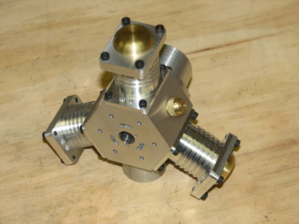
It is the time for the next project. This time I have selected the Potty three cylinder air engine. Plans can be found on this site.

I will be making some relatively minor changes to the original design including not using metric screws. I have modeled all of the parts and produced new drawings with inch dimensions. I find it less error prone if I do not need to do the translation from mm to inches on the fly.

I ordered the material I needed and started making chips just over a week ago. I will now try to get this build log up to date.

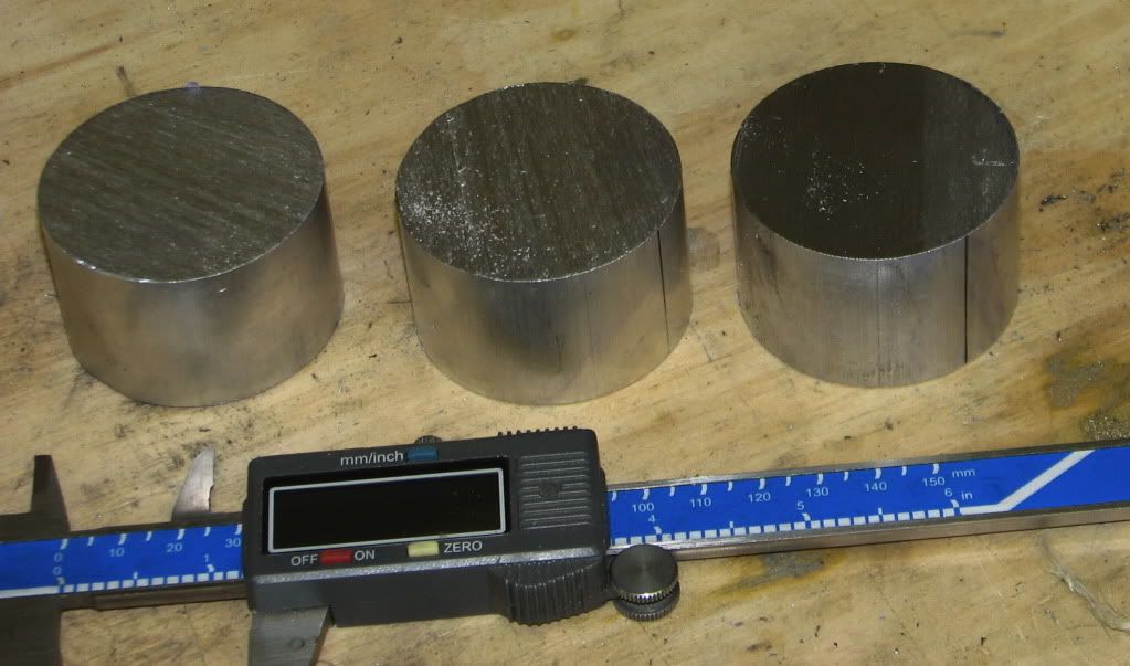
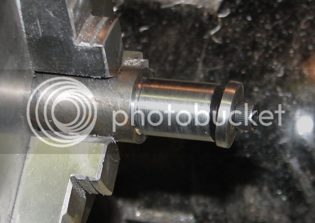
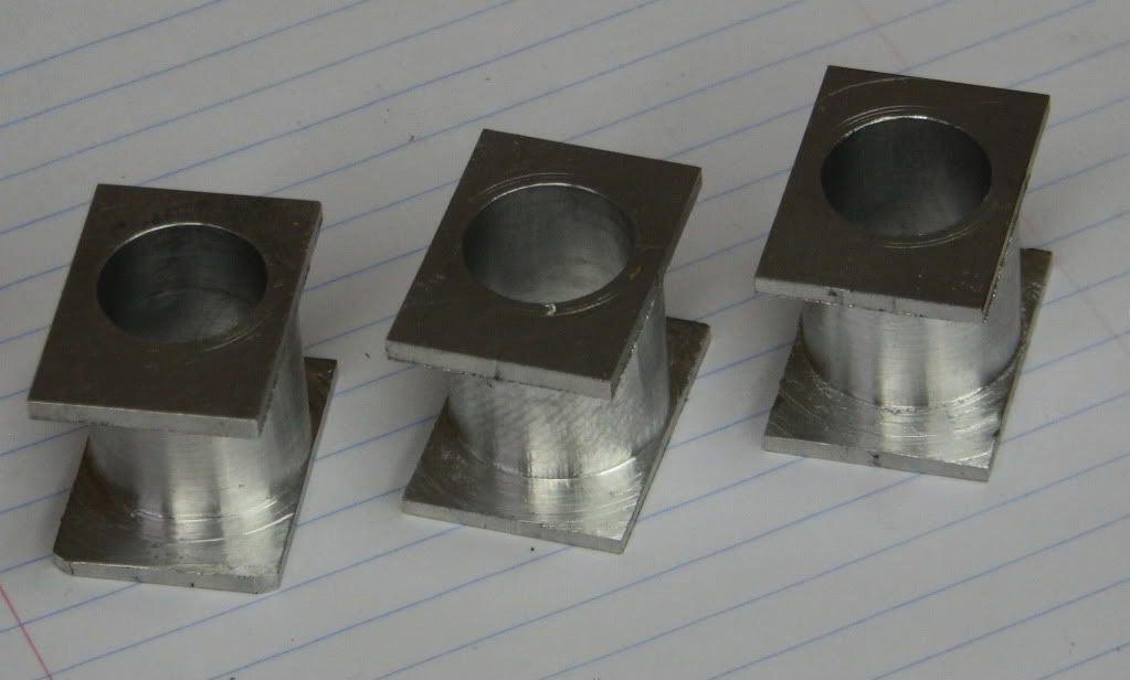
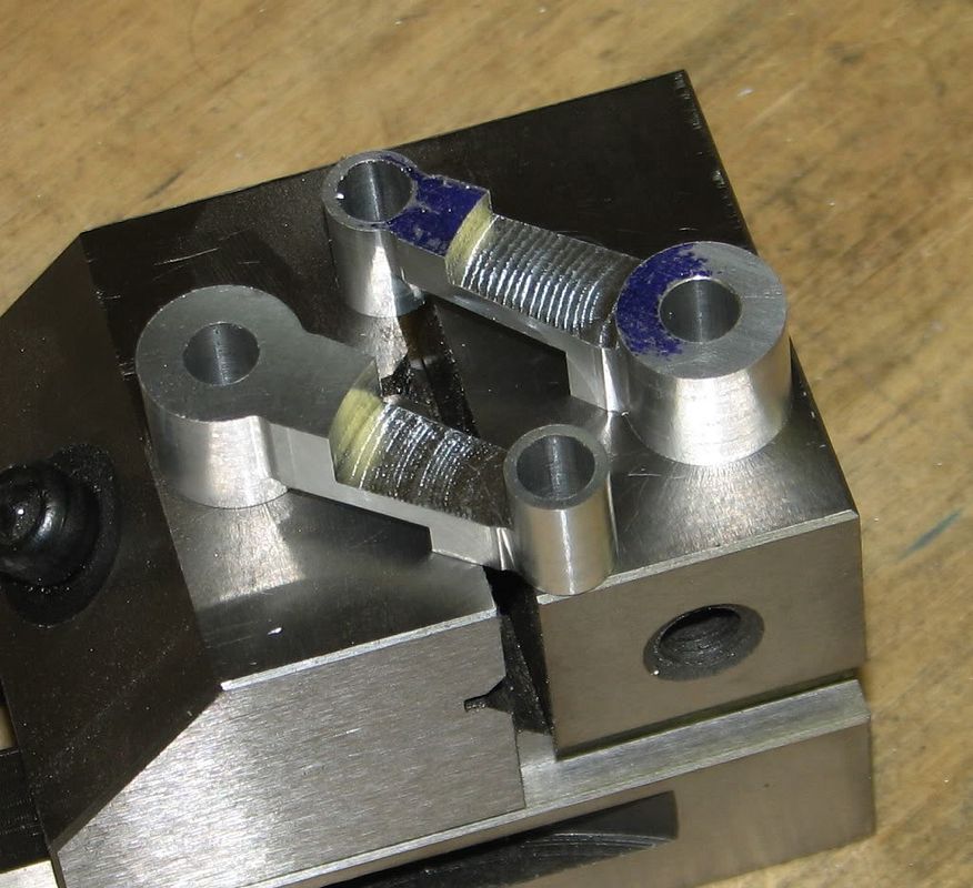
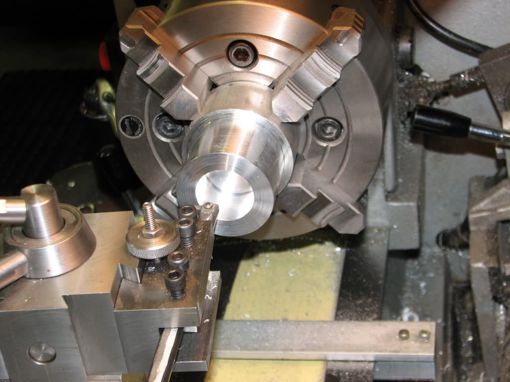
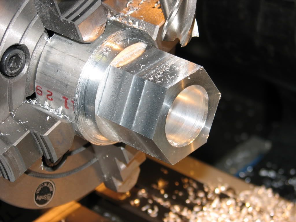
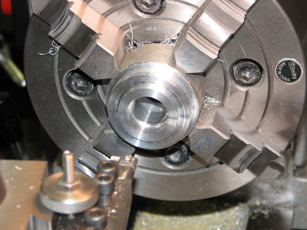
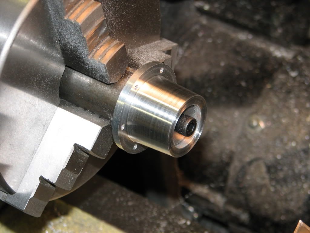
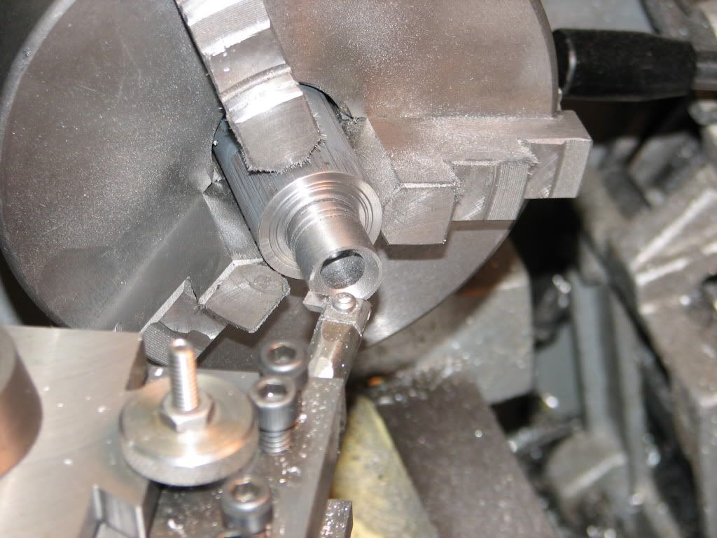
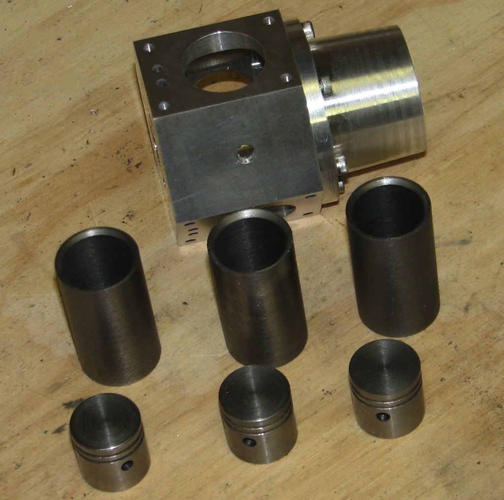
I started with the largest piece in this engine, the crank case. Starting with a 2.5 inch diameter piece of aluminum I turned a section down to 2.1 inches to reduce the amount of milling. I also bored out the central cavity. I used my 4-jaw since my 3 jaw is on the small size and would not grip as well as the 4-jaw.

Crankcase1.jpg


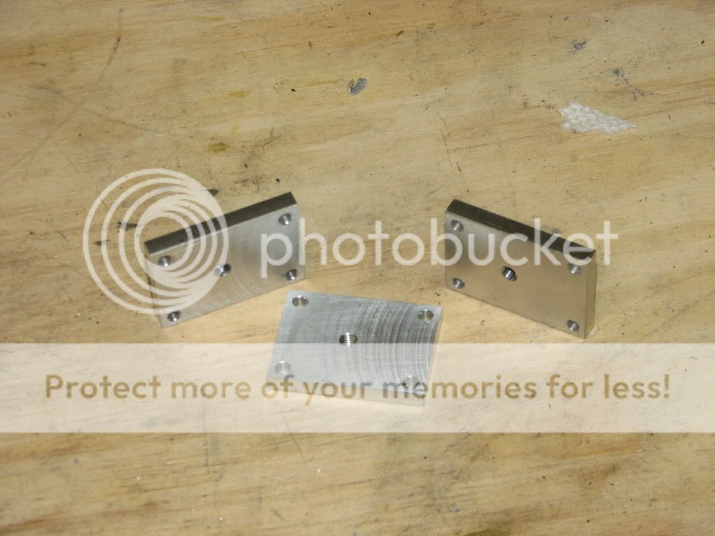
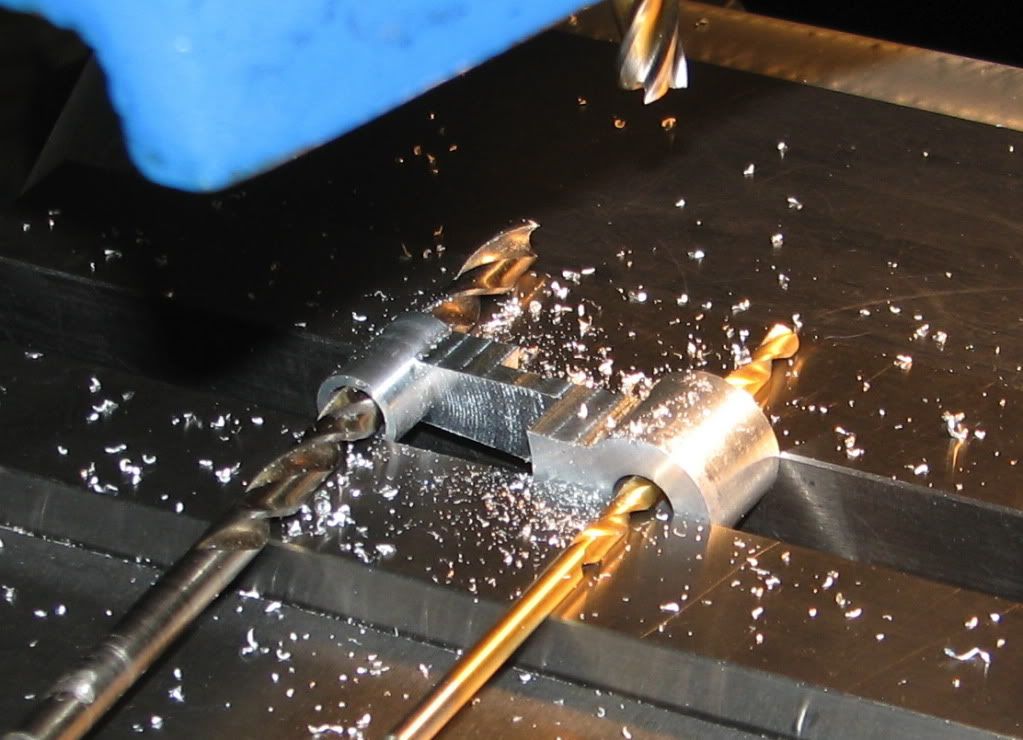
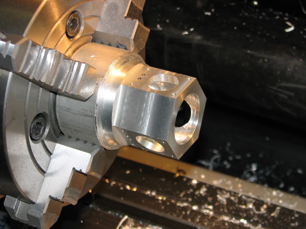
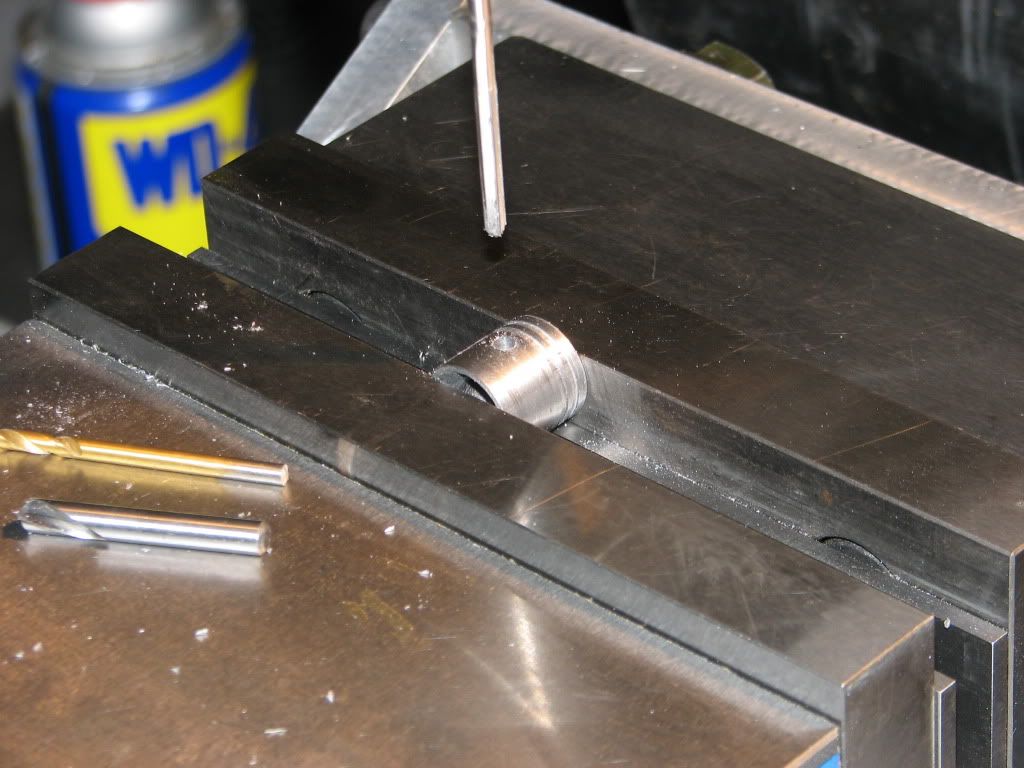
Next I move the chuck with the part to the h/v rotary table on the mill. After milling the hex shape I drilled and tapped all of the holes on the hex faces.

Crankcase2.jpg


Crankcase3.jpg


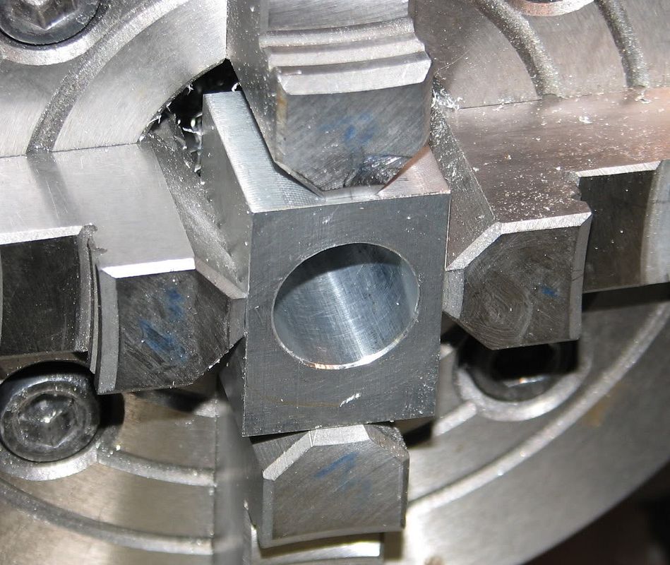
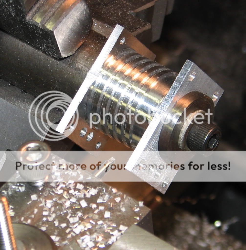
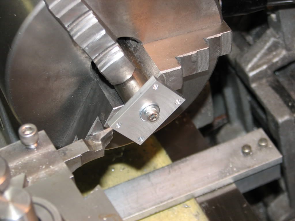
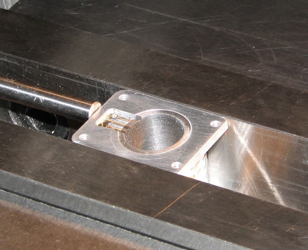
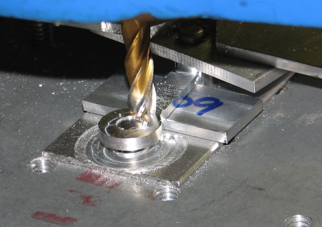
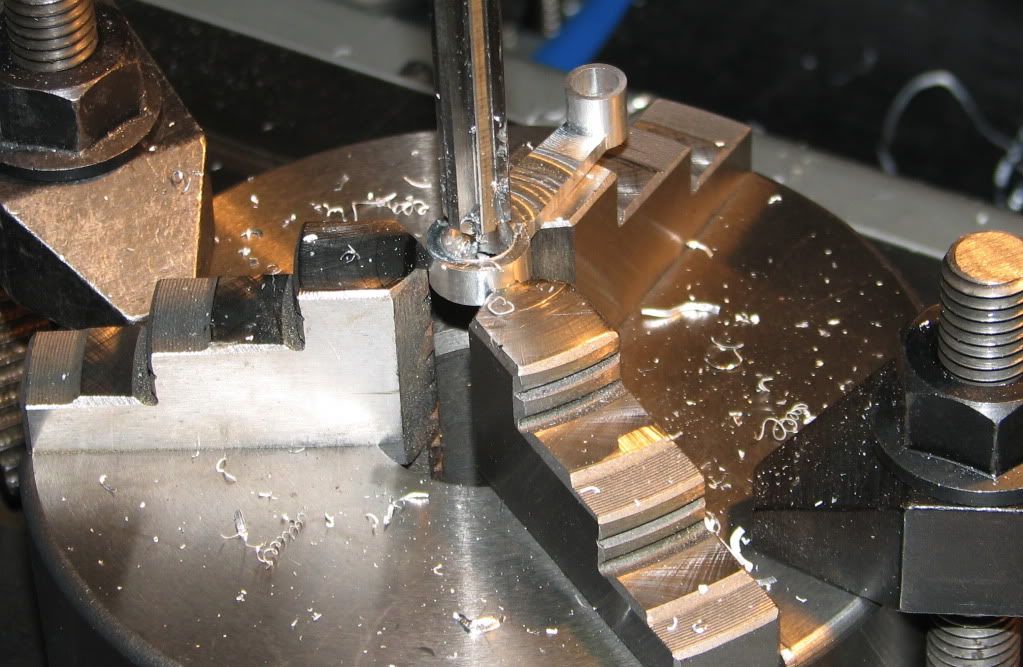
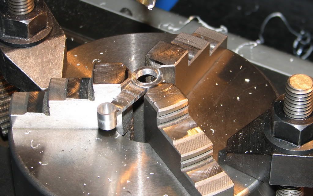
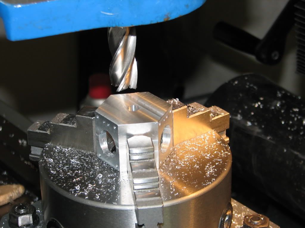
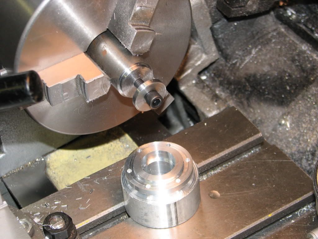
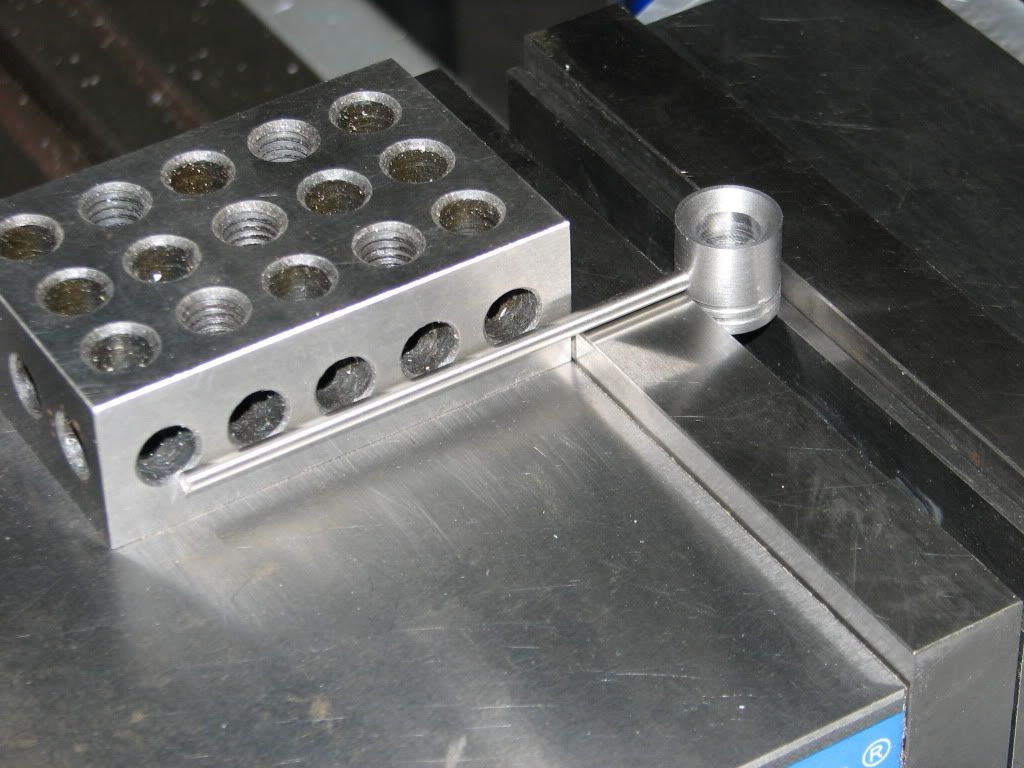
Then it was back to the lathe where I parted the crank case from its handle. Back on the rotary table, this time in the horizontal position with the 3-jaw I milled the part to length and did all of the features on the valve face.

Crankcase4.jpg


Crankcase5.jpg


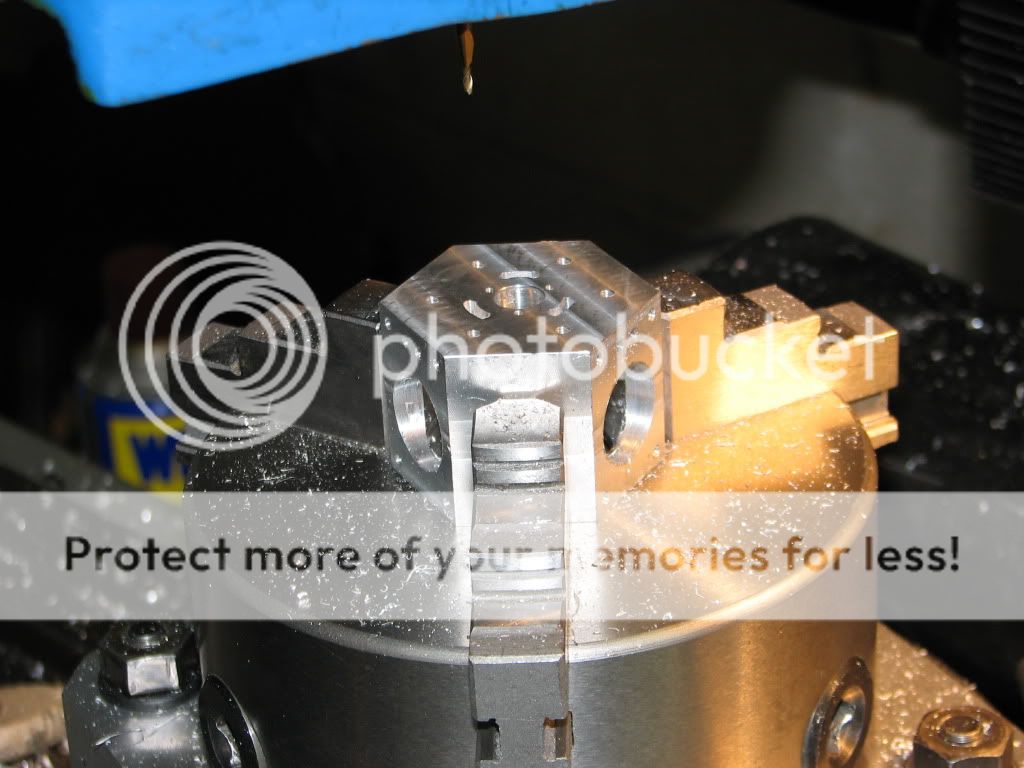
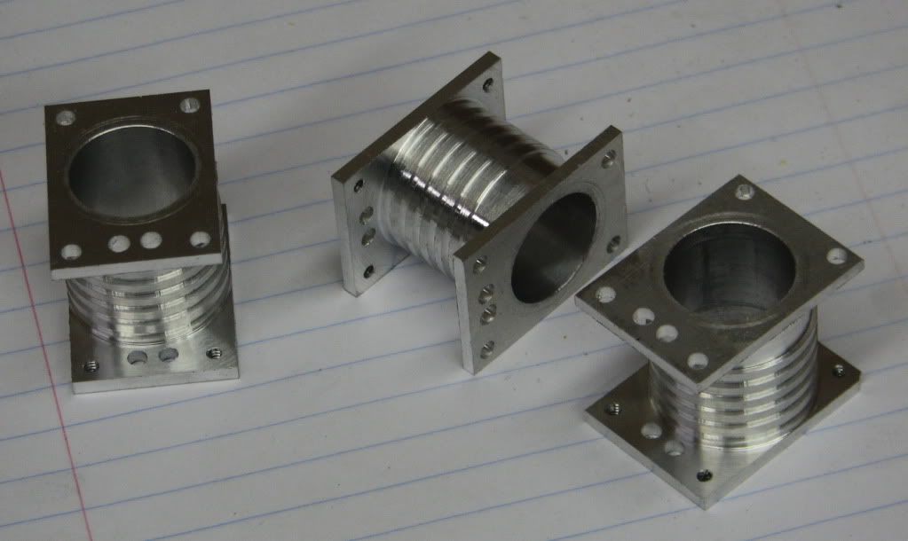
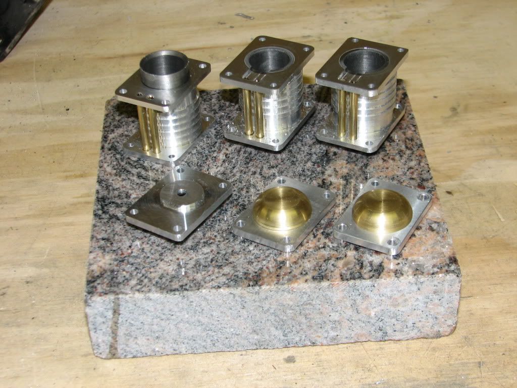
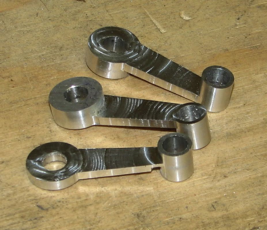
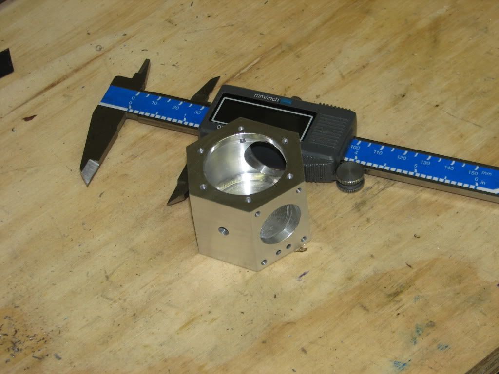
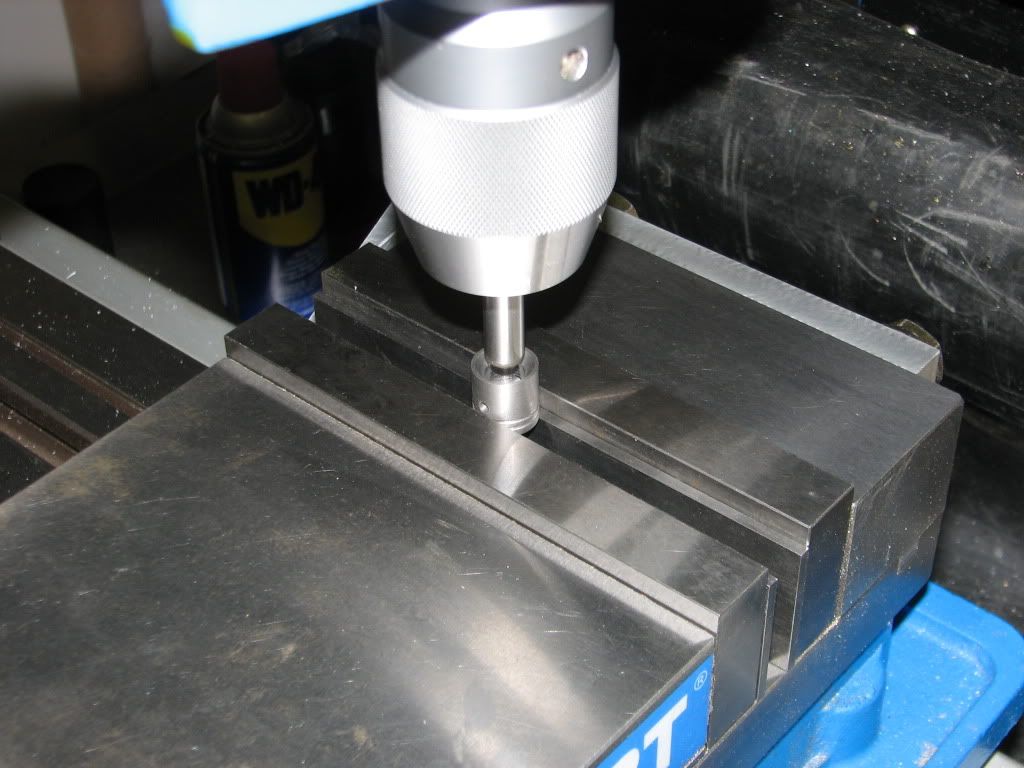
After drilling and tapping the holes on the bearing housing face and a little cleanup I had my firs finished part.

Crankcase6.jpg


To be continued

Eric
 
Next the bearing housing. This time I started with a 2 inch diameter piece and turned the mounting flange and the boss the fits inside the crank case. I also drilled and bored the bearing recesses.

Bearinghousing1.jpg


After drilling the screw clearance holes I made a simple arbor by turning a 1 inch steel rod for a slip fit in the .875" bearing recesses. Drilled a deep tap drill hole with a shallow clearance hole for a 1/4-20 bolt and parted off a thick washer. After tapping the part still in the chuck I could mount the bearing housing and face to length and turn the taper..

Bearinghousing2.jpg


Bearinghousing3.jpg


Next I worked on the cast iron pistons. This was my first time machining cast iron and it went smoother than I anticipated. First I turned the outer diameter and the groves. Next I used a .375 end mill to "drill" the flat bottomed hole in the bottom of the piston. I finished by flaring the bottom of the piston. I cut the piston from the stock and face it to length. Repeat 3 more times as I wanted an "insurance" piece.

Piston1.jpg


On the mill I drilled and reamed the .125 wrist pin hole in each piston.

Piston2.jpg


To cut the cut the square pocked in the piston I used a .125" rod and a 1-2-3 block to get the wrist pin hole parallel with the mills Y axis. I then used a .375" pin to locate the center of the piston. A few passes around the .375 diameter hole mad it a .375 square with round corners. When I was done I had 4 usable pistons.

Piston3.jpg


Piston4.jpg


I also made the cast iron cylinder liners, No pictures, just simple turning and boring.

I could not resist attaching the bearing housing to the crank case to see how they looked. Here is a photo of the progress to date.

Group1.jpg


I am now up to date,

Thanks for checking in

Eric
 
Great start Eric!
Keep the pics and comments coming, i will enjoy this thread for sure.

Norberto
 
Eric

You have made a great start on this engine. I will be watching as you progress with it as will be many others I'm sure. Keep up the fine work. :bow: :bow:

Cheers :)

Don
 
Very nicly done and shown Eric

Look forward to the next instalment.

Stew
 
Norberto, Don and Stew

Thanks for checking in and for your kind words.

Stew, also thanks for the plans that are the basis of this build.

I got a bit more done on the engine this week. I started on the cylinders. The smallest stock I had that could be used for the cylinders was 2 inch round rod. A bit large but it will work. I started by cutting 3 pieces about 1.25 inches long and then mad lots of chips. I milled the 1 and 1-3/8 dimensions about .025" over sized. This way if I am a little off on the bore it will be OK.

cylinder1.jpg


cylinder2.jpg


After drilling the center of the bore with the DRO on the mill I went to the lathe and drilled .625" diameter and bored to .750 inches.

cylinder3.jpg


Next I modified the arbor that I made for the bearing housing. I turned it to a close fit on the cylinder bores with a length of approximately 1 inch. I made a slight undercut so that the inside radius does not cause any problem. The thick washer was unchanged.

cylinder4.jpg


After a detour to make a better parting tool holder I turned down the 1 inch diameter. I will not be making the simulated fins since I do not ave a suitable tool.

cylinder5.jpg


This is it for another week.

Thanks for checking in

Eric
 
Looking good Eric,
;D


I made the tool to cut the fins from a small bit of HSS they only need to be a scratch deep, Another good source for thin grooving tools are broken hacksaw blades with a suitable holder.

Stew
 
This weeks update on the build progress.

I had limited shop time this week but did get to nearly finish the cylinders. Based on Stews comments, Thanks Stew, I made up a tool to cut the fines. I used a .125" diameter center drill that the tips had been broken off to grind a .060" wide tool. I made a simple holder from a 1/2" square piece of steel to told the tool and used it to cut the fins as shown below.The other end of the center drill was ground to use to face the inside of the flanges.

cylinder6.jpg


I still need to round the corners of the flanges but that will wait until I have the cylinder heads finished so that they can be done together. Here are the nearly finished cylinders.

cylinder7.jpg


Thanks for checking in

Eric
 
If you blacken the fins with a sharpy and gently clean the tops off with fine emery the grooves will remain black making them look deeper.

Fine work Eric

Stew
 
Stew, Eric: Thanks for the encouragement and thanks for checking in.

No for this weeks progress. I worked on the cylinder heads and cylinder boss plus the breather. The heads were stared by milling the stock to the overall size and then drilling the clearance holes and drilling and tapping an 8-32 hole for mounting on an arbor and for attaching the boss.

head1.jpg


I then faced, drilled and tapped a piece of steel so that I could turn the head to fit into the cylinder.

head2.jpg


The cylinder bosses were made from 1/2" brass. I simply faced the stock and drilled and tapped a shallow 8-23 hole before parting off a disk slightly thicker than the finished part. The disk was then mounted on the same arbor that I used to turn the cylinder heads using a short set (grub) screw. Each disk was faced, turned to diameter and then rounded with a form tool that I ground for this piece. Sorry, I did not get any photos of these operations. I also turned the breather from the same brass rod, This time using a smaller radius from tool that I had.

It this point I had to see how the completed parts looked together. Here is the group photo.

assy1.jpg


This week I plan to finish the cylinders and get at least a start on the piston rods,.

Thanks for checking in

Eric
 
Looking real good, its alway nice when you get enough parts arround you to see how things are starting to look, give you a bit of a boost. ;D

Stew
 
You're doing a real nice job on this engine, Eric. Nice proportions and nice finish.

Chuck
 
Stew, Chuck thanks for the kind words.

Now for this weeks update. As I planned I did get the cylinders finished and started on the connecting rods.

First the cylinders. First I cut the six 1/8" brass air tubes just a few thou less than the height of the cylinders. I did not want them proud of the cylinder ends when assembled. I held the tubes in place using Loctite 609 retaining compound. After a 24 hour cure I installed the cylinder liners using the same retaining compound. Again I waited 24 hours for the compound to cure. The final operation on the cylinders was to mill the air passage at the top of the cylinders between the air tubes and the bore as shown below.

cylinder8.jpg


Here are the finished cylinders

grpup2.jpg


While I was waiting for the retaining compound to cure I started on the connecting rods. I squared up some 1/2" scraps of aluminum. I also made two spacers that I will need later as well as a clamp for my tooling plate from some aluminum angle. I also drilled and reamed a .251" a hole in each rod-to-be at the location of the big end bearing. This hole will later be enlarged to .375 for a bronze bushing.

rods1.jpg


The tooling plate with .250" dowel was centered on the rotary table and the mill quill centered on the dowel and the DRO zeroed.

I made sure that the rotary table t-slots were aligned with the mill x axis and lock the rotation. With a rod to be clamped on the table and a .250 dowel through the rod and tooling plate I moved to the small end and locked the mill x and y. I drilled through the clamp, the rod to be and the tooling plate. The hole was then reamed to .251" nearly through the tooling plate. The other two rods were similarly clamped, drilled and reamed but only through the part. I could then repeatably mount the rods on the table using two dowel pins and the clamp.

Next I drilled holes at the points where the round ends meet the straight sides of the rods. I drilled the holes slightly smaller than the 1/8" diameter of the end mill I will use. The holes will serve as a guide for the shaping of the rods.

rods2.jpg


Using a 3/16" end mill I cut the round ends about .020" oversize.

rods3.jpg


After all ends were rounded I milled the three pieces to thickness while I still had straight sides to grip. This was followed by milling the sides to close to the final profile. I used a .250 dowel and a drill to set the side angle. Here are the rods after the sides were trimmed.

rods4.jpg


That is all for now.

Eric
 
Hi Eric,

The look is great !

Very cool your project...

Cheers,

Alexandre
 
Alexandre

Thanks for the comments.

I have been continuing on the piston rods. I should have more progress to report over the coming weekend.

Eric
 
I am back with another installment of the saga of making the connecting rods.

Where I left off I had the three rods roughed out. I next went back and milled both round ends to finished size. At the same time I thinned one side of each end of the central part to the final thickness. This also cut the radius at the transition from round to straight sides. Here are the two offset rods.

rods5.jpg


Next I used two drills to set the proper angle to mill the sides to their final profile. I did this while both ends were at full thickness so I could hold the rods securely for milling.

rods6.jpg


Next I finished milling the center sections of the rods. The spacers that I made earlier were used to support the part for the final cuts.

rods7.jpg


Here are the three rods to this point. If you look closely you will see that I cranked the rotary table too far on one of the parts. I do not plan to remake this part since it should not impact functionality and once the engine is assembled you will not see it (But I will know :mad:)

rods8.jpg


At this point I used the 3-jaw on the mill to hold the rods for drilling and reaming the big ends to .375" For the offset rods I could rest the rod on one of the jaws. For the center rod I had to space the rod off of the chuck face using parallels.

rods9.jpg

rods10.jpg


All that was left was to turn, drill and ream bronze bushings for both ends of the rods. I was able to achieve a good press fit for all of the bushings. No loctite was needed. A little sanding to remove most of the tooling marks and the rods were finished.

rods11.jpg


I need to decide what part to attack next. Progress will likely be slow for a while since I twisted a knee and need to limit the amount of time I spend standing in front of the machines.

That's all for now

Eric
 
Looking good Thm:

Stew
 
Back
Top