3.5" gauge live steam locomotive (first build!)

Home Model Engine Machinist Forum

Help Support Home Model Engine Machinist Forum:

This site may earn a commission from merchant affiliate links, including eBay, Amazon, and others.

syrtismajor

Junior Member
Joined
Feb 15, 2010
Messages
50
Reaction score
21
Ok, first post here for me. Been a long time browser and lurker but thought I'd finally take the plunge and post something!
This is my first proper model engineering build and is being a steep learning curve. I have never had any training in engineering (other than a 'A' in design technology at school) and my further education and work line is all laboratory based.
This all started four years ago when I was into model steam (Mamod, Wilesco, Jensen etc) and I was tinkering with them. I managed (successfully) to make a double acting slide valve cylinder for a Mamod traction engine using nothing but a drill, files and pure determination.
I was then sold an ageing Emco-Unimat SL1000 (the motor promptly blew and was replaced with a sewing machine motor!) and I started making proper chips.
At that point, someone offered me a project. A LSBC designed 3.5 inch gauge (3/4 scale) American Virginia steam locomotive. All that he had was some part turned driving wheels, part machined cylinders and some rather uniquely dimensioned (read 'slightly not to drawing') frames.
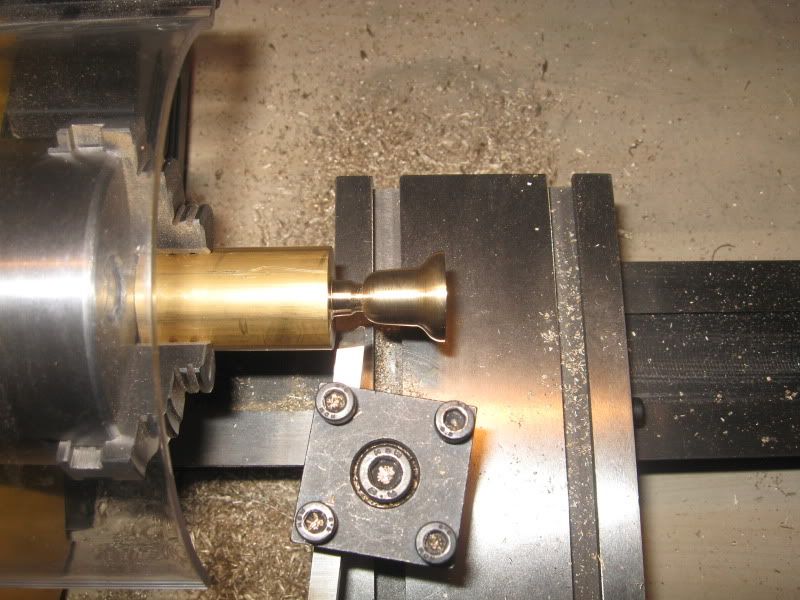
To cut a long story short (and it is a long story!), this is where I am now using my trusty Unimat and a friend with a lathe who bored the cylinders and tread-ed the wheels:

IMG_1044.jpg


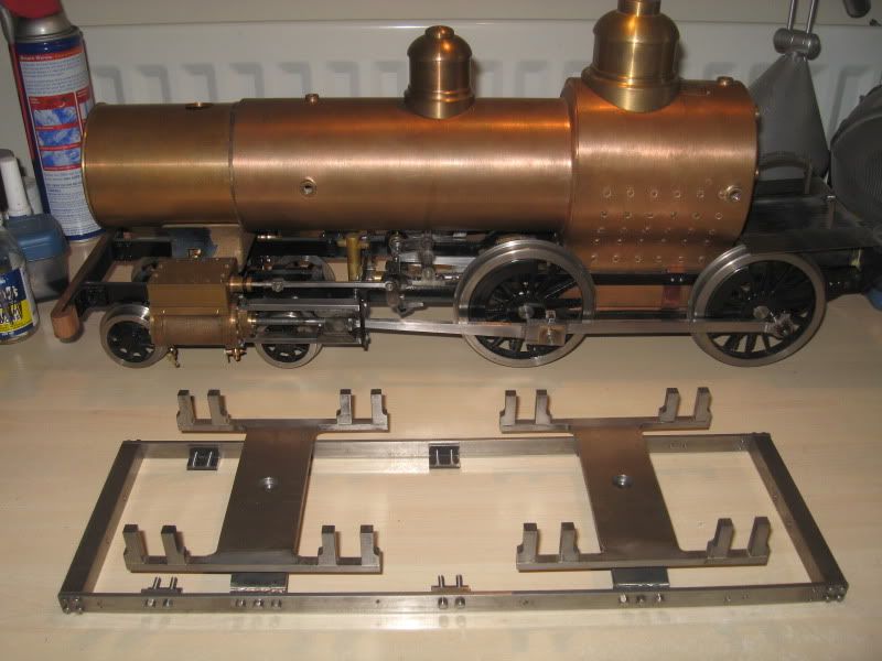
(forgive the clutter)

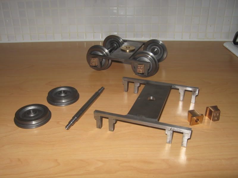
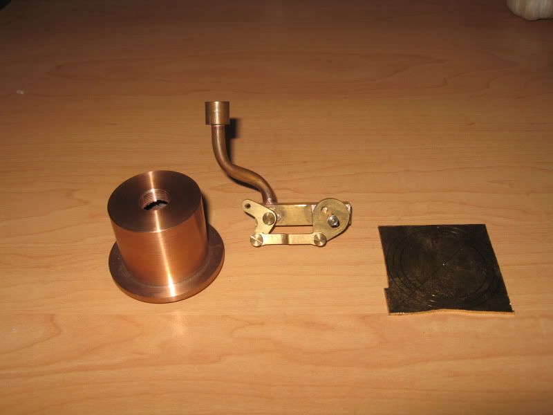
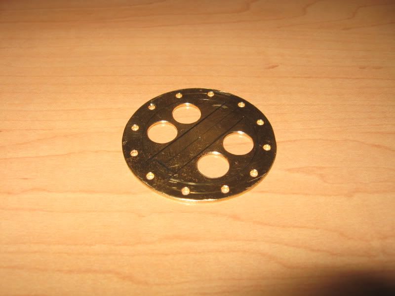
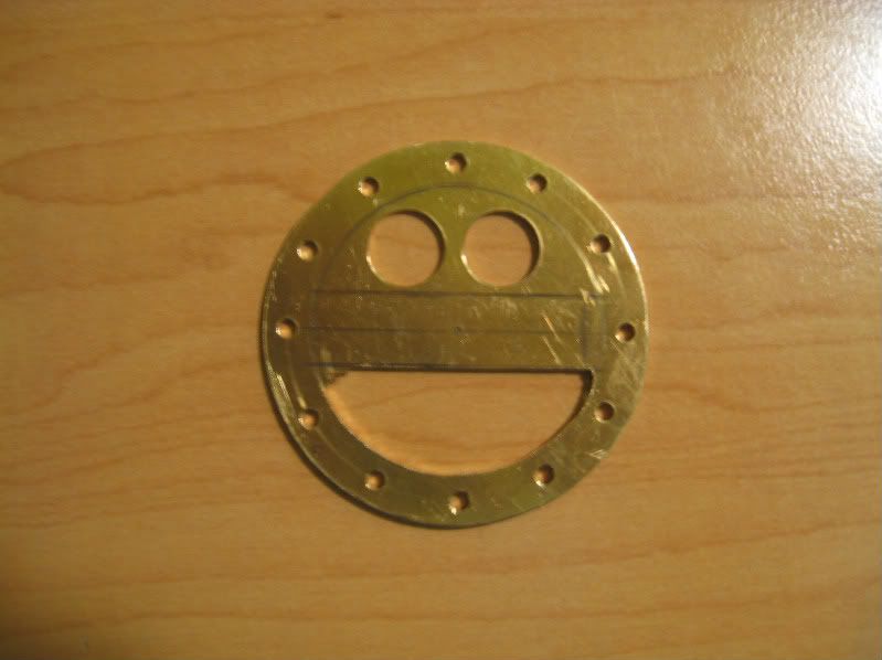
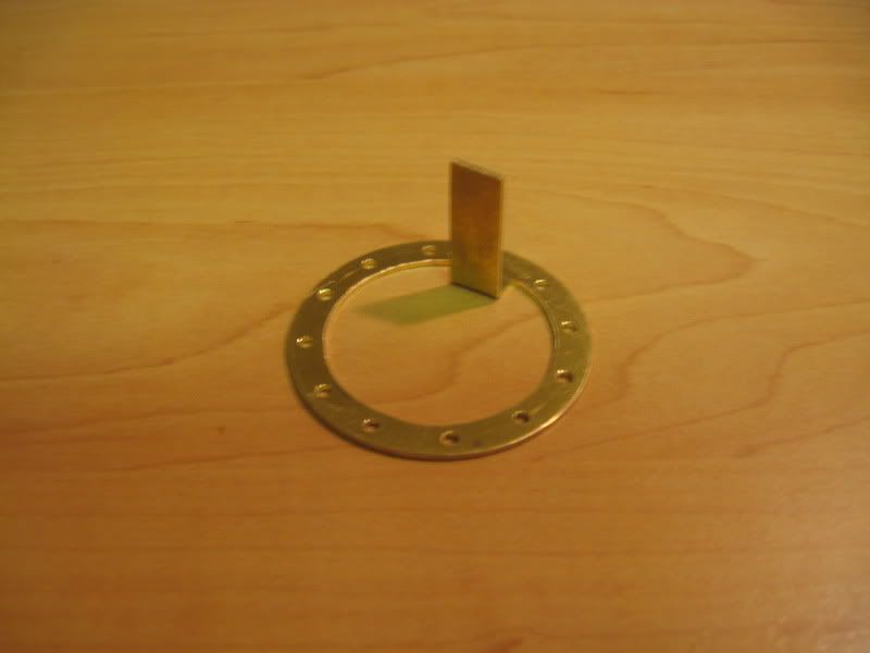
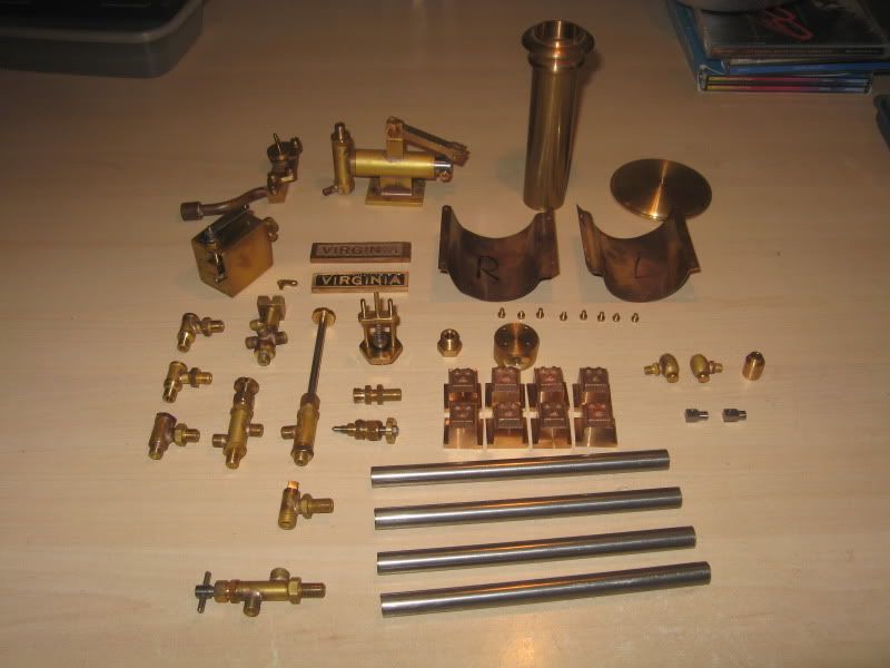
And here are some components in various stages of manufacture:

IMG_1042.jpg


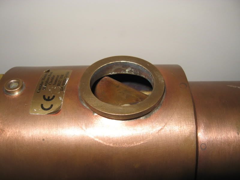
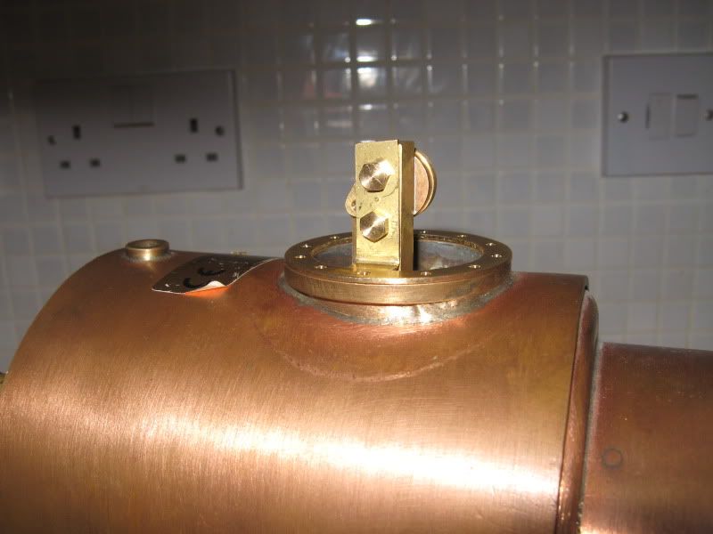
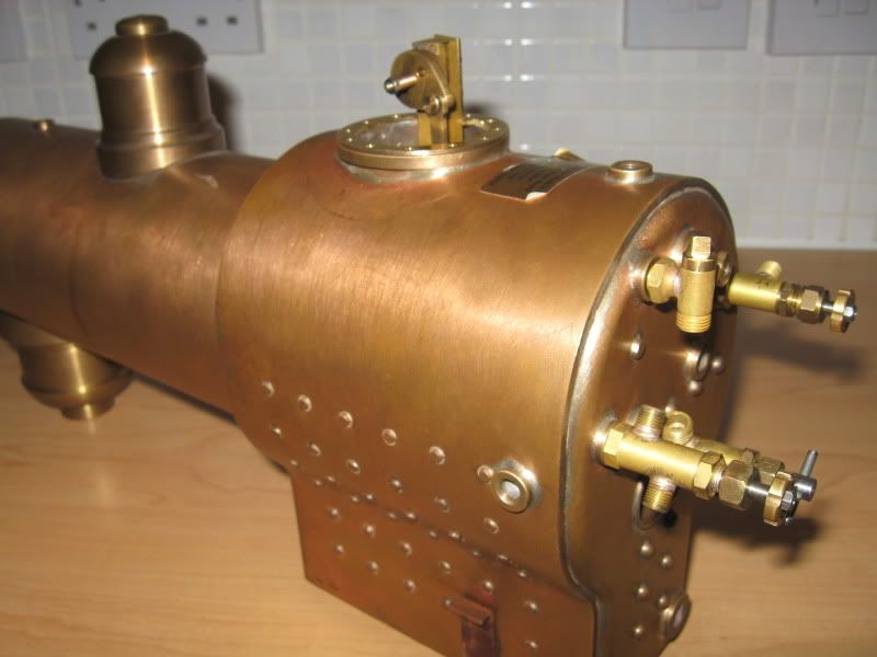
The boiler is commercially made (Cheddar models UK) which I bought second hand but unused with certification for 1/4 the cost it should have been. Other than that I have made everything you see there other than the two domes (I got with the boiler), the treads on the wheels and the cylinder bores. The frames were the ones cut by the previous owner but I have reshaped them and they do have a few erroneous holes (but they're well hidden).

And the best bit about all this so far? The chassis runs on air! (well, from a bicycle pump. One pump give about 2/3 turn of the wheels.

My next goal is to find an engineering club and get the boiler properly tested and fired up! And maybe finish the tender...
 
Wow. I am still at the basic steam engine stage (built one so far) but im looking forward to following this build. Good luck and heaps of photos please
 
very nice looking build,i haven't got there yet! i'll be watching this one
keep on posting pics and progress reports.
 
That's looking really nice, and you are making all your own fittings rather than go out any buy them.

What is the purpose of the jig?

I'm looking forward to seeing more

Pete
 
syrtismajor,
First let me commend you on a nicely turned out, crisp and workmanlike first attempt. Well done so far. I also note with great interest that Cheddar used the same dodge I have used on a couple of occasions to avoid the bother and expense of making the middle boiler course of a traditional truncated cone. That dodge being to dispense with the tapered course and run the barrel tube straight into the smokebox. Far easier (and less expensive) to do and although this can't help but reduce steam and water capacity a bit, if all else is well done the overall effect will be negligible and an argument could be made that a boiler so made will be stronger.
 
Herbiev said:
Wow. I am still at the basic steam engine stage (built one so far) but I'm looking forward to following this build. Good luck and heaps of photos please

shoprat said:
very nice looking build,i haven't got there yet! I'll be watching this one
keep on posting pics and progress reports.

Many thanks!
I will try to post plenty of pics! I haven't taken many so far and have a habit of not stopping when I'm going so I normally forget the camera until after I finished the part I was making ::)

doubletop said:
That's looking really nice, and you are making all your own fittings rather than go out any buy them.

What is the purpose of the jig?

I'm looking forward to seeing more

Pete

I chose to make my own fittings as practice due to my lack of experience with a lathe. It also helps me understand how they all work. The own thing I will buy however is the injector just so I know it works when needed!
The jig? I assume that you mean the large metal frame in front of the engine in the first photo? If so, that isn't a jig but the tender frames and two bogie (truck) frames. The whole thing is upside down in the picture. I've recently moved on with one of the bogie's and looks like this (with some in progress parts):

64270411.jpg


LBSC says to make the tender frame by bending two lengths of steel into long 'c' shapes and riveting them together. That didn't sound strong enough to me so I just used two lengths of steel bolted onto two 0.5" drag bars (all made into the same dimensions).
He also says that the bogie frames should be brazed together from eleven parts in one go! My small butane blowtorch was not up to that so the top frame was cut from a 6x7 inch 3/16" steel plate rather than fabricated and the horns silver soldered on one by one by eye without the use of a heat sucking jig.
I've also gone against convention by part maching the wheels, fixing them to the axles then finishing the tread.

GWRdriver said:
syrtismajor,
First let me commend you on a nicely turned out, crisp and workmanlike first attempt. Well done so far. I also note with great interest that Cheddar used the same dodge I have used on a couple of occasions to avoid the bother and expense of making the middle boiler course of a traditional truncated cone. That dodge being to dispense with the tapered course and run the barrel tube straight into the smokebox. Far easier (and less expensive) to do and although this can't help but reduce steam and water capacity a bit, if all else is well done the overall effect will be negligible and an argument could be made that a boiler so made will be stronger.

Many thanks for your kind words!
The boiler has been made to LBSC's specifications (other than the use of bushes for the fittings rather than threaded holes in the copper and copious amounts of plumbers mait!).
It is odd however that Cheddar have not taken into account the errors in the drawings. When made to drawing, the boiler will not fit in the frames if equalised springing for the driving wheels is used (that was a good few hours wasted machining the cast springs etc). Secondly, there is hardly any room for the blow down valve. The bushing is practically the same plane as the rear axle and only gives about 3/4" clearance :-\. That is a problem (challenge) for later on though! I'll be sure to consult these forums for advice when I decide to tackle it.

I should really say now that my old Unimat has finally killed its motor and has been sold on to a local tool merchant to be repaired and re-sold. Its replacement is a Clarke CL250M http://chronos.ltd.uk/acatalog/Clarke-CL250M-Variable-Speed-Metal-Lathe.html since I do not have space in my shared and rented flat for anything bigger! So far it seems to be up to the job and making progress much easier.
 
Thanks for the update, it obvious now you explain its the tender frames. It looks like you are doing a great job there with what sounds like constrained condition's to work in.

Next question, how did you do the Virginia name plates? A friend recently did mine on his CNC'd X3 mill and that turned out to be bit of a journey itself. (They only are 30mm long)

DSCF5862.jpg


Pete
 
doubletop said:
how did you do the Virginia name plates?

The name plates are just simple castings. I got them with the boiler, no idea what supplier they are from. I only machined one to see what it would look like and isn't of the best quality. The Virginia name won't be used anyway since I'm going to name it one of the following:
'Jack 'O' Lantern' or 'Jack Skellington'
These American loco's always seem autumnal to me for some reason (maybe because some burned wood?) and wanted the name to follow.
 
OK thanks. There aren't many DIY ways of doing these as far as I know, CNC if you've got access to the equipment or etching PCB style, although I've seen some of those and they aren't up to much either, and I suppose there is casting but then making the mould must be another equal challenge. Otherwise its commercial.

Pete
 
A minor update
I haven't been able to do much recently as the loss of the Unimat has handicapped my progress as I am now lacking even a basic milling machine. Funds are also not present to buy the milling attachment for my new Clarke lathe.
Anyway, I have managed to make the number plate! It is a little rough but I think it will add character to the engine. it was made from 1" brass rod parted off 1/8" thick and 1/16" plate for the numbers. These were drilled, filed and sanded to shape over three hours. They were then silver soldered on, flooded with red paint and the front faced off. The red paint will most likely be replaced nearer to the completion of the loco to a darker shade.
Here it is mounted onto the smoke box door:
Numberplate.jpg


Since I completed the number plate, I though I would move on to a part of the loco's voice (no matter how quiet it will be!) and started work on the bell:
Bellinprogress.jpg


(ignore the swarf ::))
Well that's all there is for now, I'll be sure to post more when something more exciting appears!
 
Been a while since I've posted here so to make up for it here is a quick photo diary of me solving a simple problem:
Here is the dome bush on the boiler: (note that there are no holes drilled, I have no idea how this boiler was hydraulically tested but I do have the certificate from Cheddar Steam to prove that it was!)
IMG_1877.jpg


I had already made the regulator about a year ago to LBSC's design out of brass and phosphor bronze. It is suppose to sit upright in the dome, held in place by a 3/32" strip of brass screwed directly into the outer firebox wrapper of the boiler.
After obtaining the boiler and having no way of providing enough heat to sweat silver solder over the screws (not to mention the following testing to ensure it is all pressure proof) and lacking the confidence to drill into such a well made (and expensive to replace) component, I decided to mount it a different way.
I toyed with the idea of fixing it to the dome but that raised even more questions. I could only mount it when the dome would be fixed in place! My skills have not yet expanded to training mice to crawl in and do it for me so I decided that a bracket sandwiched between the dome and bush was the best way to go (hopefully)
Here are the main components: (Bronze dome, regulator and proto-bracket)
IMG_1876.jpg


The bracket was made from some spare 18g brass I had left over from the folding up of the lubricator body. I marked it out with pencil using an old compass and a cheap plastic protractor and drilled through the twelve mounting holes. The holes will be used later as a template for the dome and boiler bush to ensure that they all line up. Before cutting, I also drilled out two large holes so I could easily remove the excess metal (it will make sense soon!)
IMG_1878.jpg


Judicious cutting with a junior hacksaw and filing gave me the outer shape before moving on with the internal spaces. During this I inadvertently made the happiest component in this build so far:
IMG_1881-1.jpg


Eventually I had what I wanted and bent it into the following shape:
IMG_1882.jpg


It was just then a simple matter of drilling a couple of holes in the bracket, with corresponding holes tapped 5BA (not too deep!) in the regulator. The whole assembly can now rest on the dome bush:
IMG_1883.jpg


IMG_1884.jpg


There is still a bit of cleaning up to do on it and a bit of the dome flange will have to be milled away to clear the arm of the bracket. After that is the daunting task of drilling the holes in the dome and bush.
That will have to wait however as the steel for the running boards arrived today! ::)
 
Here is the dome bush on the boiler: (note that there are no holes drilled, I have no idea how this boiler was hydraulically tested . . .
syrtismajor,
I'm building a boiler of similar size with a similar dome bush which will subsequently be finished and fitted out by the new owner, but it will be my responsibility to give it its initial pressure test. My solution for closing large openings such as this is to soft-solder a copper plate over the opening and after testing remove the plate and file away the solder residue. The new owner was happy to hear the solution because he must submit it for another test by his local club.
 
GWRdriver said:
My solution for closing large openings such as this is to soft-solder a copper plate over the opening and after testing remove the plate and file away the solder residue.

Ah, that makes sense. I suppose that is how combustion chambers are tested before fitting into a boiler? I've got the complete drawings for LBSC's 'Hielan Lassie' and that boiler looks like a nightmare to build and test!

I've since drilled the twelve 3/32" holes in the dome flange for the mounting screws. I assume that brass would be a suitable material for these fixing screws? If so I'll use commercial 7BA cheese heads (I always smile at the name of those ;D)
 
A boiler must be tested as a whole not in parts
No No to brass screws they must be bronze or stainless steel never never brass, In fact bras should not be used for boiler fittings as it suffers from having the sink leached out and then it turn to dust
I would recommend that you join a local club and talk to the boiler inspector before doing much more work on the boiler

In the UK

first test to twice WP all others to 1.5 WP


that boiler was tested in the time honoured method of soft soldering a patch over the regulator bush and melting off after note I said soft solder not silver solder

See my avatar its the boiler for a class 4 tank in 5 inch gauge about 60 pounds in weight and many more in quids , the loco is about 4 foot long and a two strong man lift
 
lordedmond said:
A boiler must be tested as a whole not in parts

That I am aware of. I had just read on other build logs that people have tested combustion chambers for leaks before they are fitted into the rest of the boiler and wasn't quite sure how they would do that

lordedmond said:
No No to brass screws they must be bronze or stainless steel never never brass

That is why I asked in my post, to make sure I was going to be using the correct material. I only assumed that brass screws could be usable as they wouldn't penetrate the boiler.

lordedmond said:
In fact brass should not be used for boiler fittings as it suffers from having the sink leached out and then it turn to dust

Having spent a fair time messing around with smaller model steam engines I am familiar with de-zincification and seen what it can do to brass. Before making my steam fittings I did confirm that all the commercially available ones were also made of brass hence why the backhead fittings and regulator body are made of the material

lordedmond said:
I would recommend that you join a local club and talk to the boiler inspector before doing much more work on the boiler

I am in the process of looking for a club to join. Unfortunately my local club doesn't seem very welcoming in that they have ignored my e-mails to them. I did tried to talk to them on two occasions, the first time the treasurer spent more time paying attention to my partners breasts than me, on the second time he just mumbled and walked away.
I am not actually doing any work on the boiler until such a time that I have on hand advice. This is one of the reasons why I am this forum so I can avoid any potential mistakes or serious errors. All items I am making are removable if they are unsuitable, and I have no intention of pressure testing the boiler or any of the fittings until I am part of a club and it has been thoroughly gone over by an inspector

I hope this alleviates any fears, and thanks for your advice

 
I am surprised that you cannot find a friendly club in the UK ( as shown in your profile ) please put up for all to see as the help for loco boilers is very country specific

as for boiler fittings that why I make them all from bronze


My current build is number 6 and is currently at the 5 year stage with about 3 more to go mainline true scale ( rivet counter ) takes a lot of time

 
It's only my local engineering club that don't seem that welcoming, or at least that is the impression I have gotten from the couple of members I have spoken to. There are others in the area but they are at least 20 + miles distant. This makes things awkward as I am one of the few people in their late twenties that does not drive a car (never had a lesson and strangely proud of it!)
I have a lot of respect for true scale model builders as I could never have the patience to do so. I would like to build other engines after this one, but as representations of the full size with concessions made for ease of construction etc.
As for my profile, I'll get on to updating my profile soon :)
 
Update!
I am still here after a rather exciting start to 2012 (mostly medical related unfortunately due to an unknown and unwanted growth in the brain that was succesfully removed in February... well on the mend now thankfully)
A few things have changed on Virginia recently including me trashing the main frames (not made my me). There were just too many mistakes in them for me to continue while retaining any shred of sanity. A quick email to an engineering firm meant that I quickly got hold of some laser cut frames. These are being drilled and finished now and everything should be back on them in a month or two.
I'll be sure to post some more updates over the coming weeks!
 
Being a steam loco guy with no car will be a challenge. :eek:

I know :-[ !

Thankfully I have an understanding partner who is more than happy to transport me about in her car. This should be helpful in the future!
 

Latest posts

Back
Top