
You are using an out of date browser. It may not display this or other websites correctly.
You should upgrade or use an alternative browser.
You should upgrade or use an alternative browser.
3” boiler project.
- Thread starter DJoksch
- Start date


Help Support Home Model Engine Machinist Forum:
This site may earn a commission from merchant affiliate
links, including eBay, Amazon, and others.
glue-itcom
Well-Known Member
- Joined
- Apr 10, 2013
- Messages
- 216
- Reaction score
- 298
Hi Doug, I forgot I had a piece of fish tank hose in the base of one of my steam engines, which was ok when running on compressed air. However, I then got excited when my first boiler was working and quickly connected the engine to the boiler. I connected it with proper fittings and copper pipes. However, it started to run and then the plastic pipe came apart. Luckily I was outside and so could remove the heat and stand well away.I was wondering if someone was going to comment on the fish tank hose. I will install an insulated hard line to the base with a solid mount to avoid any stress on the boiler Itself. I’m deciding on a means of connection. A flange mounted to the boiler base would be simple enough with the same off the engine displacement lubricator. I also found some neat little 1/8” quick connectors. The problem is finding flexible high pressure hose that will handle the heat. It would be nice to be able to simply plug in the device. Also need to see if the quick connector can handle the heat.
PS: The boiler you've made is excellent.
Best regards, Nigel
Hi Doug,
to repeat: I use 1/8" BSP connectors, with olives, for the copper tubing carrying steam to any device. Quick to connect and secure when connected. Lagged with cotton string wound around the pipes and painted with domestic white emulsion paint look just like "asbestos" lagged pipes in proper real engine houses... (DON'T use asbestos though! - Just too much risk of harm to you! Banned in the UK now.).
K2


glue-itcom
Well-Known Member
- Joined
- Apr 10, 2013
- Messages
- 216
- Reaction score
- 298
I made the engine attached to the lamppost
I did replace the fish tank tube with wrapped copper. This setup is actually in another post where I reworked this engine. It needs something to do and I like the generator and lamp post. I’ve collected parts to build another boiler and will start on it over the Christmas break. I’m planning to build a Yarrow type.
Richard Hed
Well-Known Member
- Joined
- Nov 23, 2018
- Messages
- 2,380
- Reaction score
- 615
Send that extra power to California , they needs it.And for fun,
I made a lamp-post! - for a boiler + engine + generator that has nowhere to send the electrickery!
K2
Hi Doug: Well done in selecting the Yarrow as a model boiler. I full size these were a very popular design for many reasons, not least their steaming capacity. But there is a lot of work in correct fit and assembly - and maybe fixing some leaks - before the boiler is "tight". Make sure your design gives good access to all tube joints. And for silver soldering: "Cleanliness is next to Godliness". But don't forget "correct fit".
If you want me to check calculations for your tube sizes, etc. before you spend money on expensive copper, just send the details directly to me.
Cheers!
K2
If you want me to check calculations for your tube sizes, etc. before you spend money on expensive copper, just send the details directly to me.
Cheers!
K2
Thanks Nigel: I'm sure I read about this - either in this website or in a magazine, or on your website. Great model - inspired my "not very ambitious" lamp-post! - which will be powered by one of Luke Cringle's generators! (OK that's cheating, but I made the lamp-post anyway) K2I made the engine attached to the lamppost
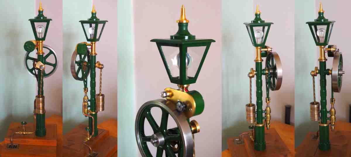
Hi Nigel, Just FYI... I did a bit of research into Lamp-post styles... It appears that the style you represent was a gas lamp, with open bottom for the lamp-lighter to insert his flame-on-a-stick when lighting the lamps.
The first real "standard" lamp for street electric lighting was a tall lamp-post, tubular section (cast iron with a more modern style of base than the Victorian "flowery" castings). The top was a simple 180degree curve, braced with some curley-cues. (Puzzled by this spelling!). - see photos.. the 2 x PB photos are my simple model...
Cheers!
K2
Attachments


glue-itcom
Well-Known Member
- Joined
- Apr 10, 2013
- Messages
- 216
- Reaction score
- 298
Hi K2, I like the model and far from simple. Cheers, NigelHi Nigel, Just FYI... I did a bit of research into Lamp-post styles... It appears that the style you represent was a gas lamp, with open bottom for the lamp-lighter to insert his flame-on-a-stick when lighting the lamps.
The first real "standard" lamp for street electric lighting was a tall lamp-post, tubular section (cast iron with a more modern style of base than the Victorian "flowery" castings). The top was a simple 180degree curve, braced with some curley-cues. (Puzzled by this spelling!). - see photos.. the 2 x PB photos are my simple model...
Cheers!
K2
Thanks Nigel, just not up to your standard of finish. But it works.
Doug, I have an inherited Yarrow. How are you getting along with yours? They do need a continuous water feed from an engine driven pump or something. Mine is only 95% completed as too many other projects have taken precedent.
K2
Doug, I have an inherited Yarrow. How are you getting along with yours? They do need a continuous water feed from an engine driven pump or something. Mine is only 95% completed as too many other projects have taken precedent.
K2
I have the materials. I’m staring at it while working on my latest side track engine project and studying Yarrow designs. I like the concept of domed end caps for the main and side tanks, but I want the look of copper rivets. I’m actually at a hold up while I determine how to swedge the tubes or if it is actually needed.
Hi Doug, I like the idea of hemispherical ends too. I have not considered the "design" aspects - how to calculate min material thickness, etc. and whether the "better" design inserts the dome end into the tube, or the tube into the dome end? - I guess the former looks better? - As to "simulating" rivet heads, all I can suggest is a series of rivets soldered in place... but semi-scale rivets on a boiler that will be well lagged - or at least inside the smoke-box casing? - Maybe no-one will ever see them? But you could rivet the casing!
Attached some pics of the boiler I inherited - and made a ceramic burner and casing for... - but haven't yet made the water gauge and feed-pump inlet. Of course it steams, but the burner is relatively HUGE for the ability to maintain water in it... You can see that the casing hides all the tubes, so however you join the hemispherical ends just has to be a good engineering job, and the casing has to be pretty! (My Black paint isn't, as the paint has charred!). The bottom tubes were made from some brass wave guide stock the guy had, and after doing some tests and measuring distortion of the large flat sides against boiler pressure, this cannot exceed 30psi = TEST pressure. Therefore the NWP is 15psi! A simple "kettle" horizontal cylinder is stronger and holds more water.. so I have been considering making a "water reservoir" - connected to top and bottom tanks and well lagged - so the water "volume" is increased to a workable amount, to avoid the top tank boiling dry at the tube joints. I could then even move the safety valve and ullage to be in the reservoir, making the top tank a permanently full tank.... But needs more thought as to the operation engineering of such a system? Getting the steam from the Yarrow top tank to the reservoir will be a bit of a concern, as these are such rapid steamers in the water tubes.... The Biggest problem with Yarrow designs is the arrangement so there are convection down fed water tubes (often un-heated?), and hot "steaming" risers.... so a reservoir tank may do that very well, or very badly! Then "Possibly?" a new casing to contain BOTH Yarrow boiler and reservoir, so the reservoir gets some extra heat from exhaust flue gases? It is a "pending" job now... for a boiler that doesn't have an engine or ship to take it.
On display, it doesn't attract much attention - except with the few in the know... - as it just looks like a black casing anyway.


So maybe you need to think a bit more about yours - before deciding on the final design? K.N.Harris - model Boilers and Boilermaking - has a design (12) with a 2" top tank and only 2 rows of water tubes either side... But if I were to make one for proper use, it would be 3" or 4" diameter top tank. But silver soldering 60-odd tubes (leak-free!) will be a real problem and proof of your copper-smithing!
Have fun!
K2
Attached some pics of the boiler I inherited - and made a ceramic burner and casing for... - but haven't yet made the water gauge and feed-pump inlet. Of course it steams, but the burner is relatively HUGE for the ability to maintain water in it... You can see that the casing hides all the tubes, so however you join the hemispherical ends just has to be a good engineering job, and the casing has to be pretty! (My Black paint isn't, as the paint has charred!). The bottom tubes were made from some brass wave guide stock the guy had, and after doing some tests and measuring distortion of the large flat sides against boiler pressure, this cannot exceed 30psi = TEST pressure. Therefore the NWP is 15psi! A simple "kettle" horizontal cylinder is stronger and holds more water.. so I have been considering making a "water reservoir" - connected to top and bottom tanks and well lagged - so the water "volume" is increased to a workable amount, to avoid the top tank boiling dry at the tube joints. I could then even move the safety valve and ullage to be in the reservoir, making the top tank a permanently full tank.... But needs more thought as to the operation engineering of such a system? Getting the steam from the Yarrow top tank to the reservoir will be a bit of a concern, as these are such rapid steamers in the water tubes.... The Biggest problem with Yarrow designs is the arrangement so there are convection down fed water tubes (often un-heated?), and hot "steaming" risers.... so a reservoir tank may do that very well, or very badly! Then "Possibly?" a new casing to contain BOTH Yarrow boiler and reservoir, so the reservoir gets some extra heat from exhaust flue gases? It is a "pending" job now... for a boiler that doesn't have an engine or ship to take it.
On display, it doesn't attract much attention - except with the few in the know... - as it just looks like a black casing anyway.
So maybe you need to think a bit more about yours - before deciding on the final design? K.N.Harris - model Boilers and Boilermaking - has a design (12) with a 2" top tank and only 2 rows of water tubes either side... But if I were to make one for proper use, it would be 3" or 4" diameter top tank. But silver soldering 60-odd tubes (leak-free!) will be a real problem and proof of your copper-smithing!
Have fun!
K2
Attachments


Your boiler has some interesting design elements I had not considered. I arbitrarily picked an 8” overall length. Here’s what I have.
2-1/2“ main shell at .075” wall thickness
1-1/8” secondary shell .055”
3/8” tubes at .03”
I also have a 1’ section of the 3” tube I used on the completed boiler. I’m thinking 50lbs as the target pressure. It has to push the new tandem engine project with 2” crank throw with two 1.2” inline cylinders. I was sketching out an 8” boiler with 20 straight tubes per side. I‘ve seen several designs with a larger return tube to the lower drums, but I’m not sure if this is actually needed. The plan is to build another ceramic burner to heat it. Have a few design elements to work out. I will check out the text.
Attachments

Hi Doug,
I have fiddled with my spreadsheet to check hoop stresses...
(But hope I haven't made any chumbos! - Xcel has the habit of changing a formula when I copy a column and re-enter basic size data... and I sometimes miss the obvious error! - fixed 2 errors, but did I find them all?).
Here's what I figured:
As noted for the "bottom" tubes you propose (results above), you could go to 60psi NWP, but NOT HIGHER. The safety would be set for full pressure relief at "NOT EXCEEDING" 63.5psi, but if you keep to 50psi NWP the safety shall be set "Not Exceeding" 53psi.
Test pressure for 60psi NWP = 138psi; but if 50psi NWP => test at 90psi.
NOW to steam consumption: or maybe tomorrow..
Too busy now.
Hope this was of some interest?
K2
I have fiddled with my spreadsheet to check hoop stresses...
(But hope I haven't made any chumbos! - Xcel has the habit of changing a formula when I copy a column and re-enter basic size data... and I sometimes miss the obvious error! - fixed 2 errors, but did I find them all?).
Here's what I figured:
- TOP TANK (allowing for stress concentration of wall penetrations - e.g. for Safety Valve, water tubes, etc.): 2-1/2“ main shell at .075” wall thickness: Looks like the hoop stress is 2621psi versus a limit (ASME) of 3950psi: so OK.
- Water tubes: 3/8” tubes at .03” : Looks like the hoop stress is 134psi versus a limit (ASME) of 3950psi: so OK.
- BOTTOM tubes (allowing for stress concentration of wall penetrations - e.g. for water tubes): 1-1/8” secondary shell .055” : Looks like the hoop stress is 2958psi versus a limit (ASME) of 3950psi: so OK. - The sensible ASME limit would be 60psi NWP for this size of tube: So you have an extra margin of safety.
As noted for the "bottom" tubes you propose (results above), you could go to 60psi NWP, but NOT HIGHER. The safety would be set for full pressure relief at "NOT EXCEEDING" 63.5psi, but if you keep to 50psi NWP the safety shall be set "Not Exceeding" 53psi.
Test pressure for 60psi NWP = 138psi; but if 50psi NWP => test at 90psi.
NOW to steam consumption: or maybe tomorrow..
Too busy now.
Hope this was of some interest?
K2
Ok Doug, you are most welcome to check anything of your designs with me, and I'll try and give sensible answers, or tell you when I can't.
Just a thought. How long are the water tubes? One row or 2 per bottom tube?
Cheers!
Ken
Just a thought. How long are the water tubes? One row or 2 per bottom tube?
Cheers!
Ken
Similar threads
- Replies
- 4
- Views
- 419