1886 Benz

Home Model Engine Machinist Forum

Help Support Home Model Engine Machinist Forum:

This site may earn a commission from merchant affiliate links, including eBay, Amazon, and others.

Tom T

Well-Known Member
Joined
Sep 22, 2007
Messages
121
Reaction score
20
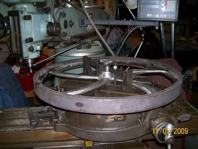
I've started my winter project. But I have held off posting anything because my projects sure do start off ugly. I am building a full scale 1886 Benz. I have the original patten and some really good pictures but no actual blue prints. What I basically know about this is it has a 3.5" bore, and a 6" stroke. It has a total engine weight of 220 pounds and creates 3/4 hp at 400 rpm. Here are a few pictures of the progress so far. If work stays slow this project should move along pretty fast. If I don't make to many mistakes along the way. The preview post does not work. So this could be a mess. Tom T
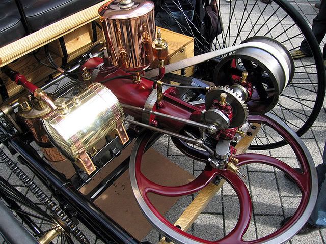
Here is a picture of a reproduction I got off the net.
800px-Benz_Patent_Motorwagen_Engine.jpg

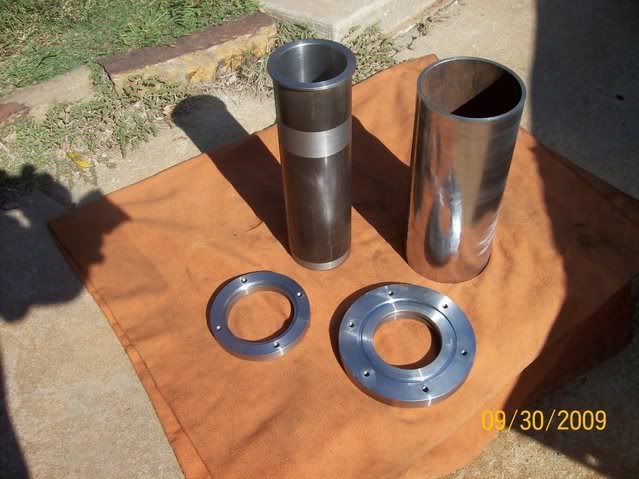
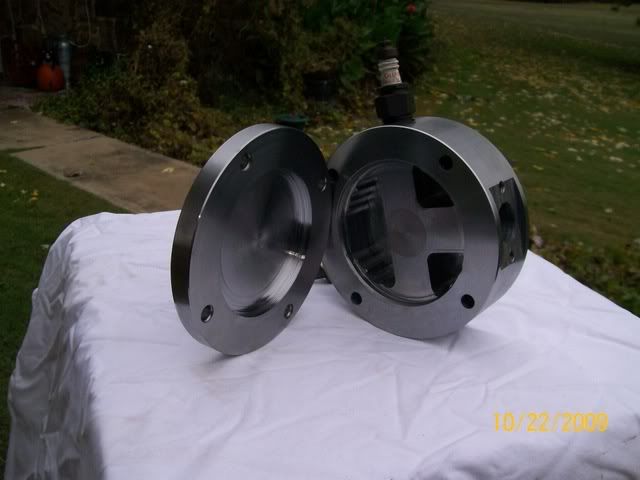
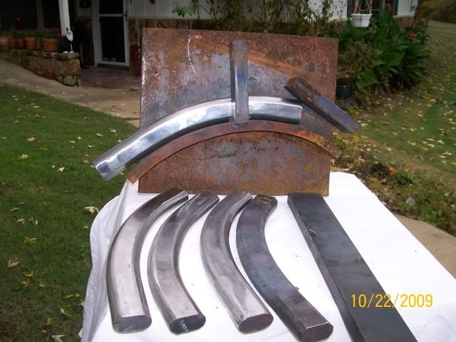
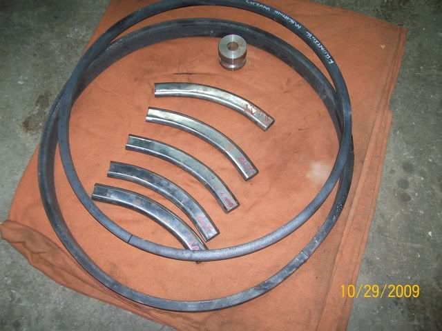
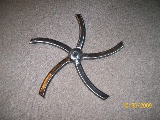
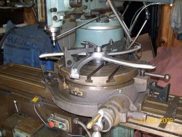
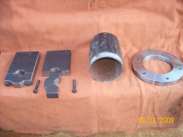
Here are some of the parts that make up the crank case.
100_2198.jpg

100_2202.jpg

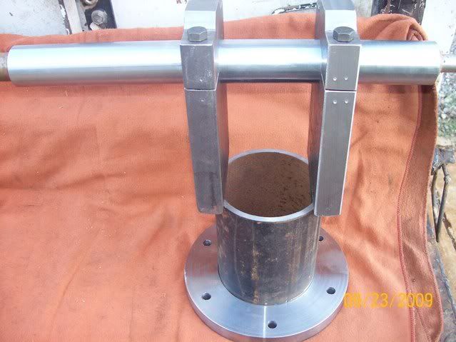
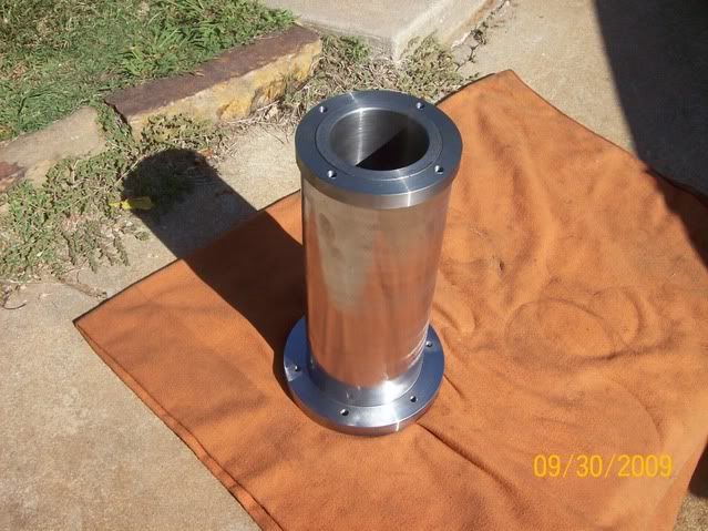
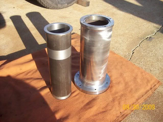
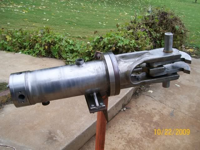
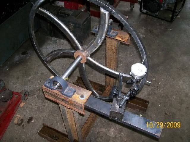
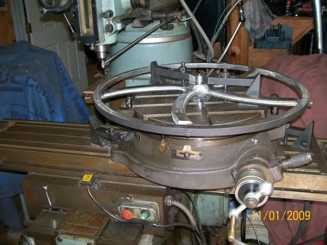
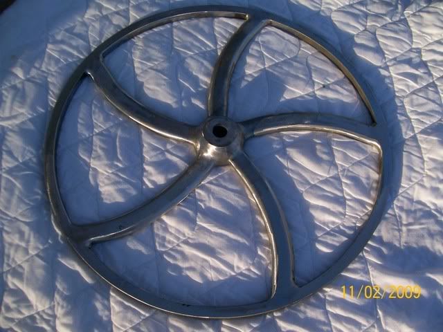
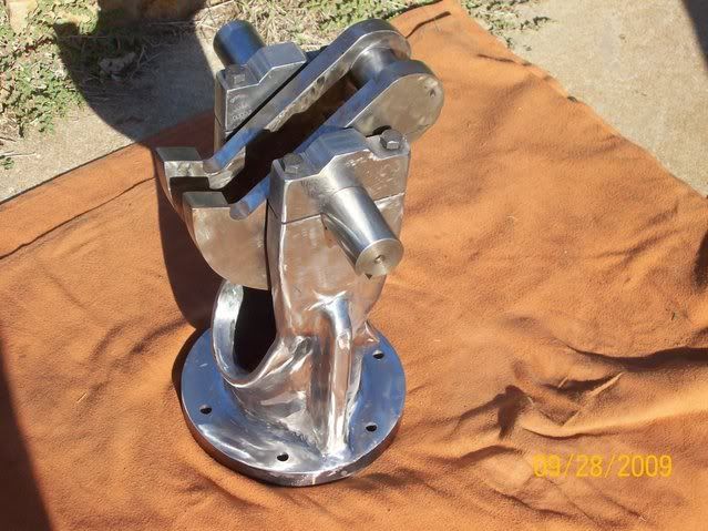
Here it is after welding and lots of grinding.
100_2218.jpg


I wish you well with this project and am looking forward to seeing progress. Its certainly ambitious and what an end product! Will you be doing all your own castings? Good luck MM
 
Hello Tom,
This is a challenging project.
A modelengineer colleague here in Holland has build one some years ago. It ran very good. Because of storage problems he had t sell the car. Now some Mercedes dealer has it in his showroom.
The builder now is left with a scale model 1 : 8 witch is a runner as well. Maybe the modell you got from the net is his???
Good luck with your build.
Nemt
 
Wow!
I dont think I have ever seen anybody fabricate a part to look cast that looks that good.
How long did it take?
-B-

 
You HAVE to take us along on this ride Tom!

That is a beautiful engine that I would love to see the
step by step progress going.

Rick
 
lazylathe said:
Hi Tom,

Looks fantastic!

Maybe this will help, some pics at the end!
http://home.arcor.de/carsten.popp/DE_00037435_A.pdf

Andrew

Firstly Tom, that is an awesome start! Good luck Ill be watching with interest (much!). Secondly, Lazy, man that is a great find. If I were Tom and I didnt have much to work with, you would be my hero right about now. Good post mate.... :bow:
 
That photo looks like the one at the Owls Head Transportation Museum in Maine. Do you know if it is, or is there another replica around?
 
Wow, Tom, I'm impressed. I've been looking longingly at the Henry Ford Quadricycle. Mostly just the engine.

Wish you the best on this project.

Chuck
 
MM--- I am not using any castings. I am going to fabricate them and weld and grind.

Krown Kustoms--- So far about a week off and on. 2 days of that was grinding. :mad:

Lazylathe---- That is the exact drawings I have. But thanks for them anyway.

RonGinger--- Don't know if that is the one from Maine or not. There are some replicas in the UK. A company there made about 15 of them.

cfellows-- you should build the ford and we will have a race. Thm:

Rick--- Will try to keep everything documented and updated. Thanks for this wonderful site. Tom
 
Here are a few more pics. This is the parts that make up the cylinder. The 2 rings are welded to the larger tube to make the jug. The liner will slide down in it and seal with an o-ring in the bottom.
100_2224.jpg

This is what it looks like now all assembled
100_2226.jpg

This is after the welding
100_2228.jpg
 
That's a beautiful engine in the first picture, Tom, and from the looks of things you're off to a fine start. All your grinding time on the crankcase was well spent. It's impressive!

Does this engine have a spark plug? I'm almost sure I've seen one somewhere, but if I remember right, it had a hot igniter. Is yours the same?

Hope you keep us updated on this build!

Dean
 
Nice pictures, Tom. I'm really impressed with the work you did on the cylinder. Looks like a cast iron liner? How did you bore it and get it so smooth?

Chuck
 
Dean I will be using a sparkplug and buzz coil like the original engine had.

Chuck the liner is a piece of d.o.m. tube with a flange welded on . I have built liners like this for other engines and had no problems. If it gives me trouble I will bore it out and press in a cast iron sleeve.

This is a picture of the cylinder head it was made in two pieces so I could hollow out the coolent passages. The valves are mounted on the outside of the head, intake is a slide valve and exhaust poppet .
101_1297.jpg

This shows the engine assembled and brings you up to where I am at on this engine. Next will be the flywheel. Tom
101_1295.jpg
 
Hi Tom

:bow: :bow: :bow: :bow: VERY NICE , i do like your fabrication work ;D ,,,,,,, whats your plans for the fly wheel ?and what diameter is it ?

Regards Rob
 
words cannot express what you are undertaking :big:
 
I'm really impressed, Tom. Can't wait to see how you do the flywheel!

Chuck
 
Thank you for your comments.
Rob its 26 inch od.
nkalbrr you made me stop and think [ not good ]
I made some progress.The spokes were cut from 2x.75 flat bar and corners cut at 45 then put in this jig , heated red hot and bent. I found this jig in my scrap pile. I made it for a flywheel I built last summer I am glad I didn't hall it off.

101_1301.jpg

This shows the 8 parts that make the flywheel
101_1305.jpg

This shows it being held together by set screws in the inner outer ring at this point the hub was tack welded.
101_1312.jpg

Here it is after welding and grinding.
101_1314.jpg

continued on the next post Tom
 
Weld was added to the outside of the spokes then mounted on a rotary table and cut to fit the inner outer ring. This helped keep it true.
101_1321.jpg

The inner outer ring was then installed and tacked to run true. Then removed for welding.
101_1323.jpg

This shows the flywheel after the inner outer ring was welded on, remounted on the rotary table, trued up, then polished.
101_1327.jpg

This shows the flywheel after the outer ring had been installed and welded to the inner ring. At this point it was milled true.
This sure would of been easier with a big lathe.
101_1331.jpg
 
Well, Tom. I see the pictures, but I'm still not sure how you did it. Very impressive! :bow: :bow: :bow:

Chuck
 

Latest posts

Back
Top