1" Bore x 1" Stroke Vertical i.c. Engine

Home Model Engine Machinist Forum

Help Support Home Model Engine Machinist Forum:

This site may earn a commission from merchant affiliate links, including eBay, Amazon, and others.
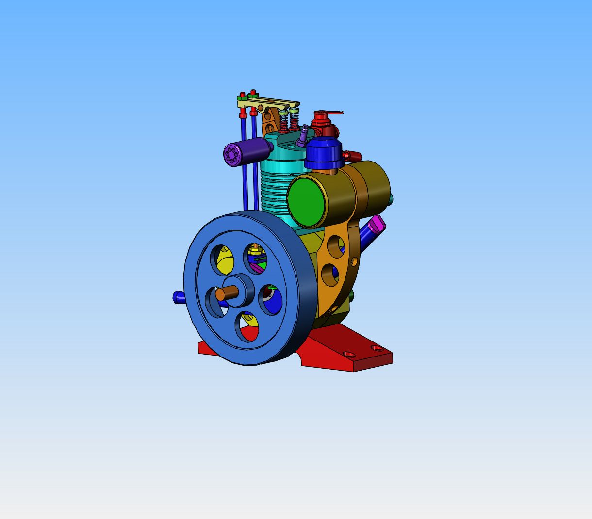
Today I determined that if I swapped positions of the carburetor and the exhaust, that would keep my gas line away from the flywheel and give me room to mount a small, belt driven fan between the flywheel and exhaust. Similar to an earlier vertical i.c. that I designed and built a few years ago, the belt would be an o-ring driven by the flywheel. I haven't shown it here, but may have time tomorrow to do some more on the design.
TxmK3F.jpg
 
I picked up my aluminum for the crank case and base today after lunch, and spent a quiet afternoon detailing. When right and left hand parts are simple, you can get away with one drawing, specifying "One as shown and one opposite hand". When they get fairly complicated there is much less chance of something getting machined wrong if two drawings are made, one of the right hand part and one of the left hand part.
Ua1zoy.jpg
Hi Brian, In case I missed it. Will you be selling sets of plans after the "little beauty" is finished? - I guess you may do some odd mods as you make... so don't expect all drawings to be finalised until then. But I like the simplicicity of this engine - it looks as they did when I was a lad! I'd be proud to make this one!
K2
 
Here we are at boss machining stage-1. All of the material that can be removed has been removed using conventional "in the vice" machining. Now it's time to step over to the rotary table and round the corners on the large end boss on both sides.
vLaYVt.jpg
 
Well, I must say---that worked out even better than I thought it was going to do. The radius on both sides only took a few minutes. Now I'll press that shaft out and loctite a shaft in the other hole so I can finish the machining at that end.
ORIM4a.jpg
 
Steamchick--yes, after the project is completed and all of the drawings updated to reflect what actually got built, I sell the plan sets for $25 Canadian funds.
 
I can't believe how well this turned out. Machining these bosses qualifies as "something I hadn't done before". Tomorrow there are about 13 or 15 holes to be added (most of them tapped). I haven't got the ball bearings yet, but they are supposed to arrive tomorrow. I don't want to separate the pieces, get all set up to bore the cavities in my 4 jaw chuck lathe, and then not have the bearings. Since there are major cavities to be bored in both halves, I have to try and decide if I should drill and tap all the holes I can now, and put up with interrupted cuts while I'm boring the major cavities, or wait until after I have bored the major cavities to put in all the threaded holes. Probably the second option makes more sense, and I do have other parts I can be working on while I wait for the bearings.
7eYYXA.jpg
 
I have enough aluminum plate and steel ring to make a two piece flywheel. Of course, this lets me fool around a bit with the design. I kind of like this. The outer steel rim would be attached to the aluminum center with steel pins which extend thru the steel flywheel into the aluminum spokes. The heads of the pins might be visible where they extend thru the outside diameter of the flywheel, then get machined flush or I might even make them from brass and let them be a design feature.
OgCq7H.jpg
 
Steamchick, if you want one that looks like you remember as a lad the original drawings that this is heavily based on can be found on the net, I assume it's you on the left!
20210201_130425[1].jpg


It was originally in Popular Mechanics with drawings for making your own castings and the machining drawings in a second issue but easy enough to cut from solid. If you search "midget gas engine 1936" or 1936 Midget Engine" you can find a few and links to the drawings. Brian has included most of the modifications to the fairly basic design that I made when building my version of it though I went with the more traditional crankcase shape, starting cord pully etc.
 
Now I need some help. I am searching for a 4 or 5 blade plastic fan or propeller that is 1.375" to 1.5" outside diameter. I'm not too concerned about the shaft size because I can make my shaft to suit. I would like to source it in North America, I don't care where it is made. I spent half an hour Googling nd couldn't find one. I want to use it as a cooling fan on this engine and I don't have room for anything larger in diameter. Does anyone have a source or a link?---Brian
 
Brian, I made a design for 3d printing a fan with no supports required. I plan to use the resulting fan on the Tower Engine ... that build that has been languishing for the lo these many months, but which I WILL get back to, hopefully sooner rather than later. What I don't know is whether the fan will stand up to the heat, even printed from a higher heat material like PETG. I'm hoping the air flow will keep the fan cool enough, but that remains to be seen.

I'm trying to find the file - apparently it is not where I thought it was. Hopefully I didn't accidentally delete it! (If so, I'll definitely recreate it). But in any case, if you are interested, I'll be happy to send it to you.
 
Cut from thin sheet twist each blade to give it some set and soft solder or loctite to a hub. Does not have to be anything fancy you can just mill some radial slots and make the outside round on the rotary table. At least that way anyone buying the drawings can do the same where ever they are in the world. Did similar for the Thompson and RMC

DSC04043(1).JPG


DSC03922.JPG
 
Thanks Jason--I know that I can make a fan. If I can buy a manufactured plastic fan finished and ready to go for the right price, I would prefer to do that.---Brian
 
Ah, found it. As shown, the hub dimensions are .575" high with .55" OD and 10mm ID (yes, sorry, mixed units - I tend to work in both, depending on what is most convenient at any given moment). The ID is sized to take MF106 flanged bearings, so that the fan can turn on a 6mm shaft. The overall diameter of the fan is 2.25", and the blades are .375" high. The fan blades start out around .06" thick and taper to around .03".

Of course, any of these dimensions can be changed to suit the need. If you are interested, I'll be glad to generate an .STL file to the dimensions you need.
 

Attachments

  • 3d fan.jpg
    3d fan.jpg
    61.8 KB · Views: 155
  • fan.stl
    5.4 MB · Views: 294
I originally generated the fan using FreeCAD, but I have put together an OpenSCAD version - this will let anyone generate fans with whatever dimensions are desired. Hopefully it is sufficiently well commented that it will be easy to use.
 

Attachments

  • openscad_fan.zip
    13.6 KB · Views: 193
Back
Top