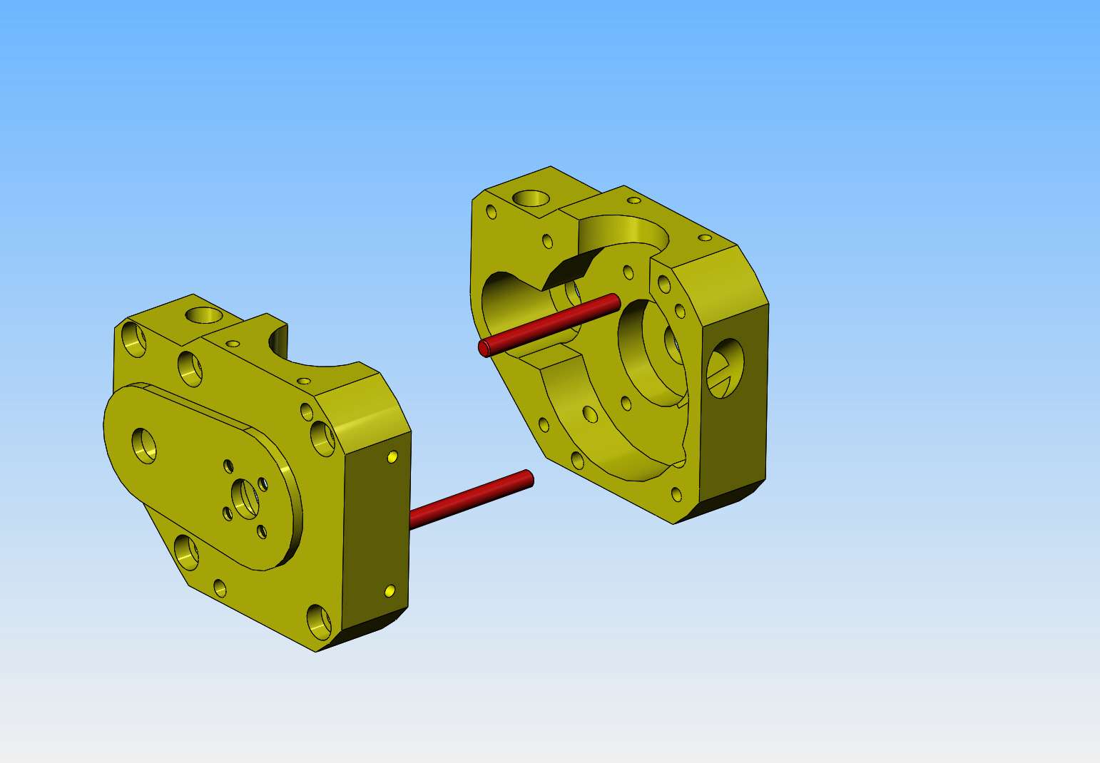
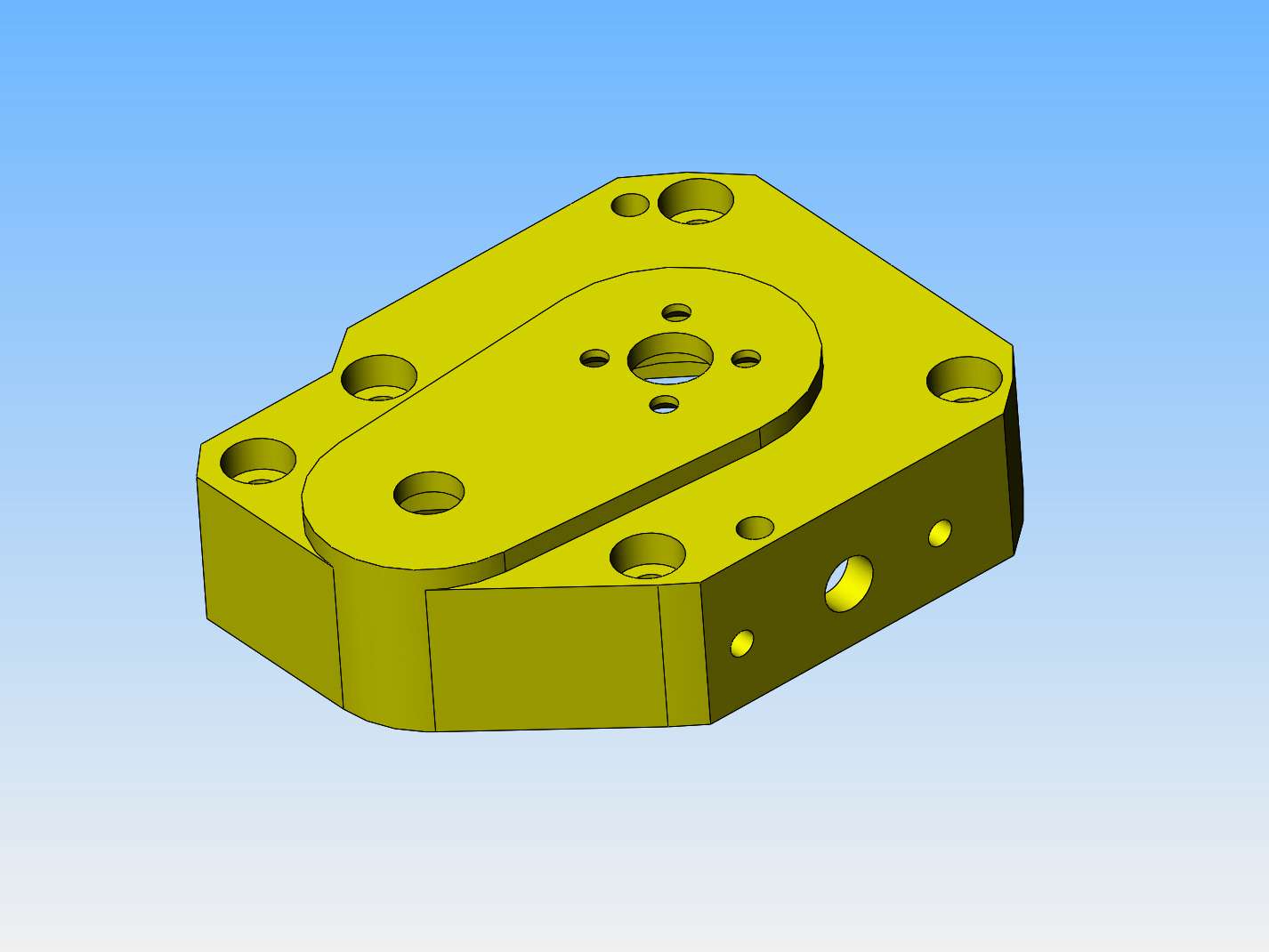
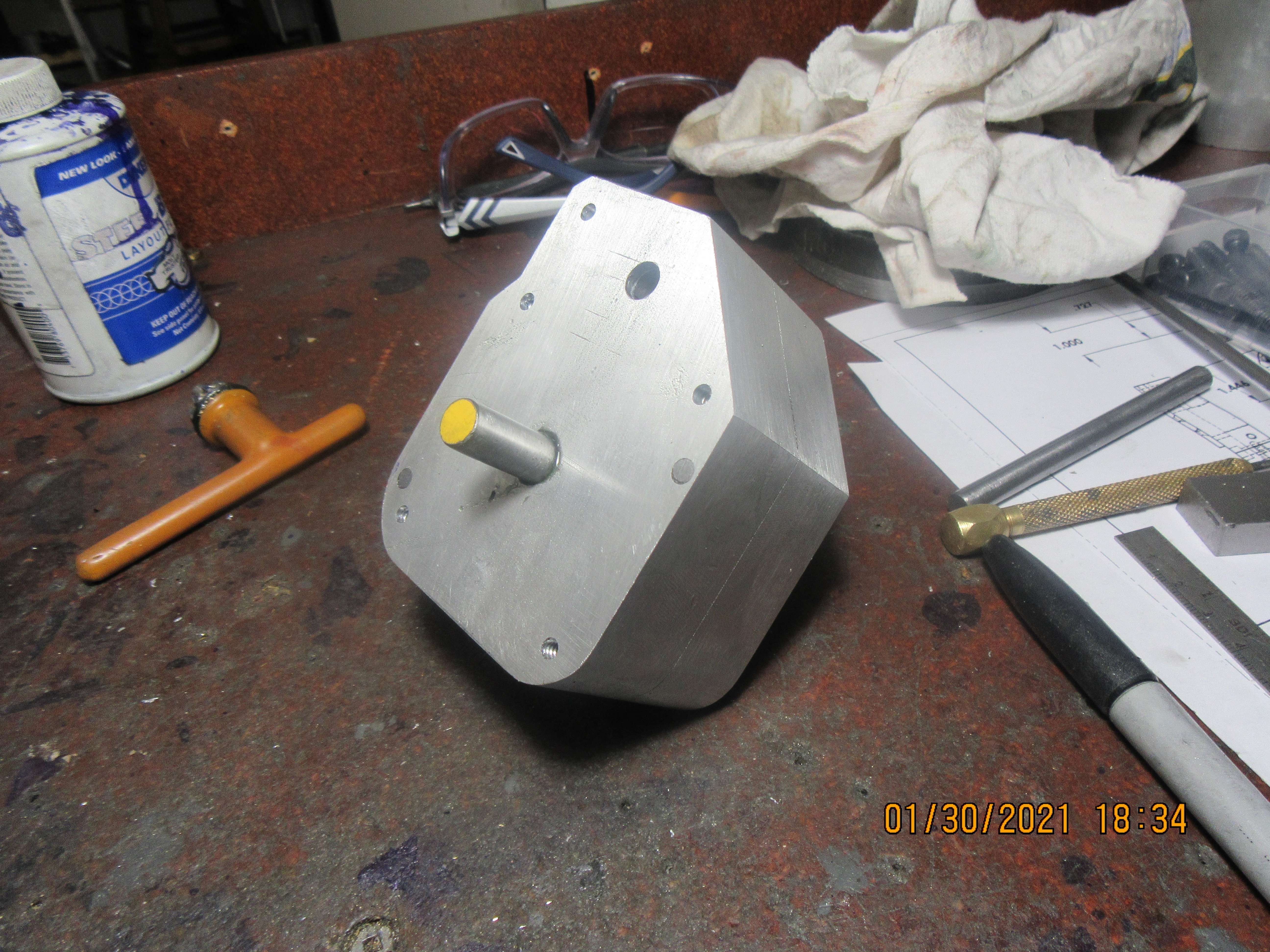
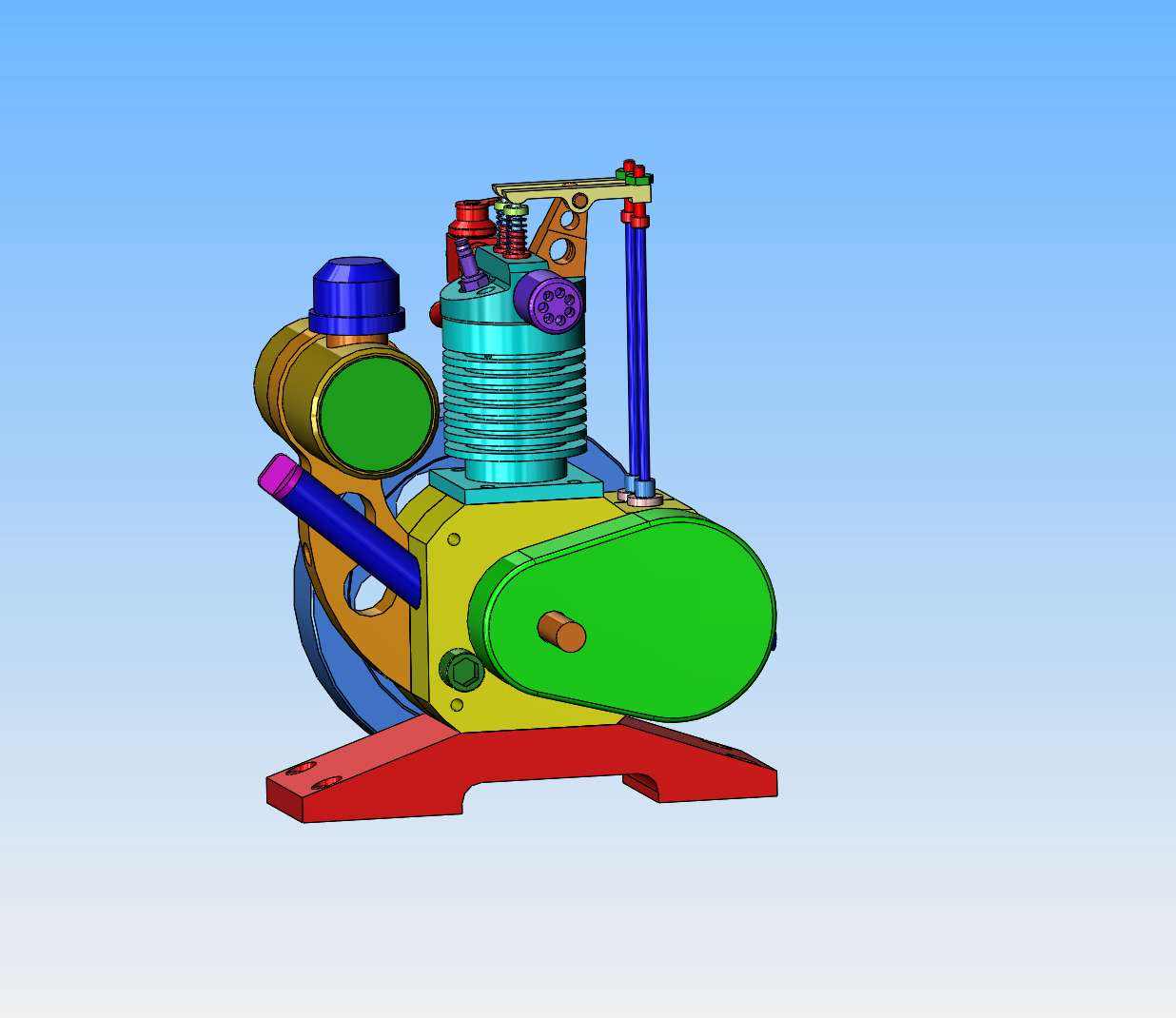
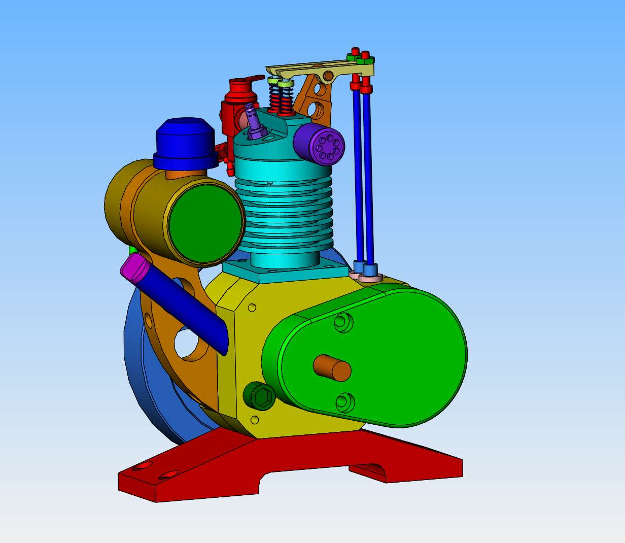
So, there we have it. The design is essentially finished. My computer tells me that there are a total of 74 individual components, not counting fasteners. The two crank-case halves are designed to be cut from 3" x 1" aluminum flat bar. The base can be cut from a piece of 2" x 1" aluminum flat bar. I haven't included the poppet valve which screws into the crankcase to keep the crank-case in a semi vacuum condition (to avoid oil leaks around the bearings), because I'm not really sure that I need it. If I find out "after the fact" that I do need it, it can always be added later. The oil filler tube and cap have been added, as well as a drain plug in the very bottom. An "oil level check" hole and plug have been added to the side of the crankcase. You can see it just to the left of the outer gear case. You take out the plug and add oil in the filler tube until it starts to run out that hole. That hole is positioned so that when oil starts to run out of it, you know the oil level is correct. All of the tapped holes and clearance holes for fasteners have been added. The only thing I haven't totally decided on is how to attach the outer gear case to the crank case. If I make it from brass $$$, I can silver solder a couple of mounting tabs to it. If I cheap out and make it from aluminum, then it becomes a different story because I can't weld aluminum.
") I make it a practice not to count the number of parts I need to make, that way I am always "just a couple of parts away from being done." Looking good, you don't mess around when puttin an engine together, I fiddle with one part longer than it takes you to crank out a whole new design.
I make it a practice not to count the number of parts I need to make, that way I am always "just a couple of parts away from being done." Looking good, you don't mess around when puttin an engine together, I fiddle with one part longer than it takes you to crank out a whole new design.