1" Bore x 1" Stroke Vertical i.c. Engine

Home Model Engine Machinist Forum

Help Support Home Model Engine Machinist Forum:

This site may earn a commission from merchant affiliate links, including eBay, Amazon, and others.
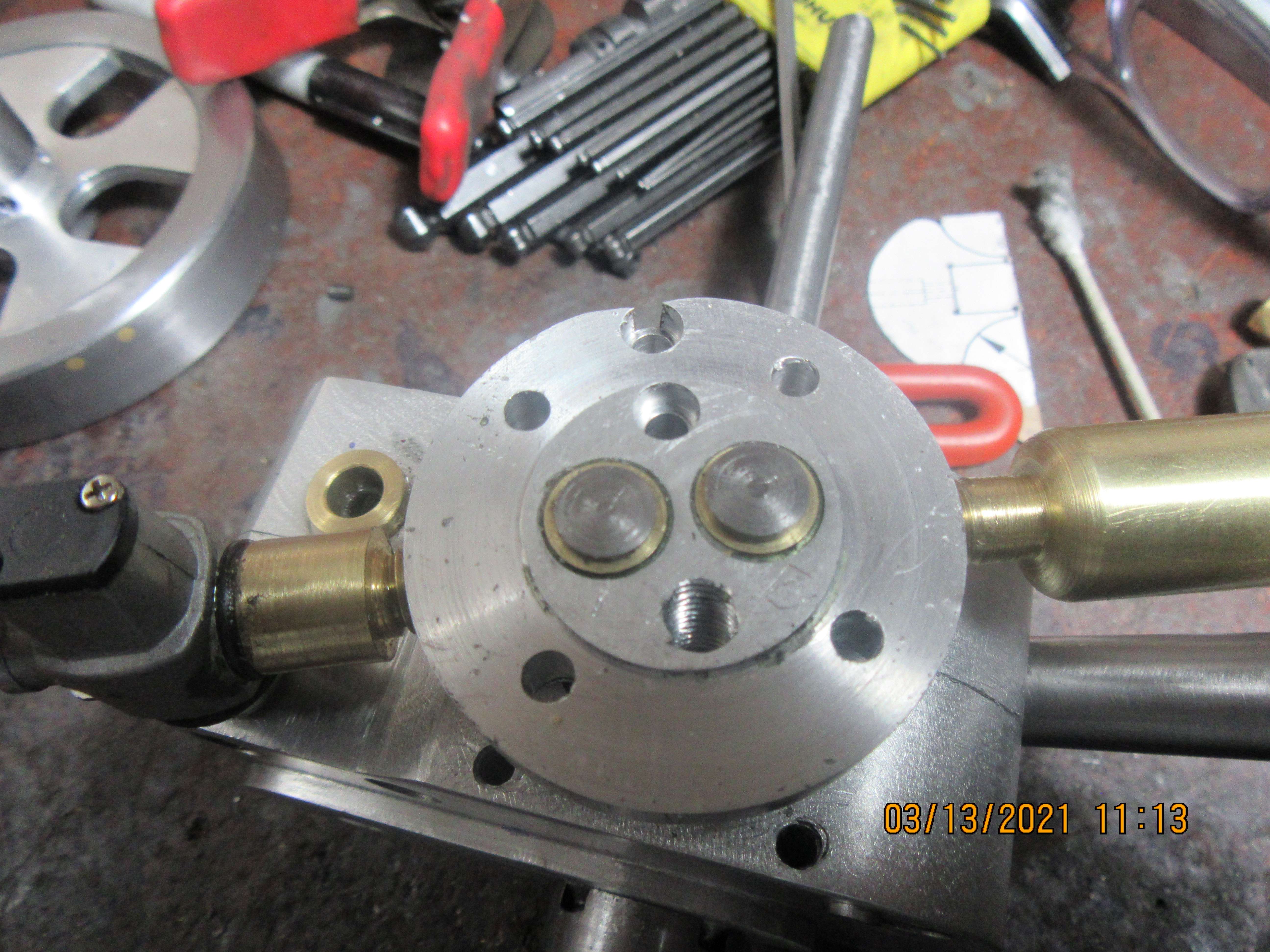
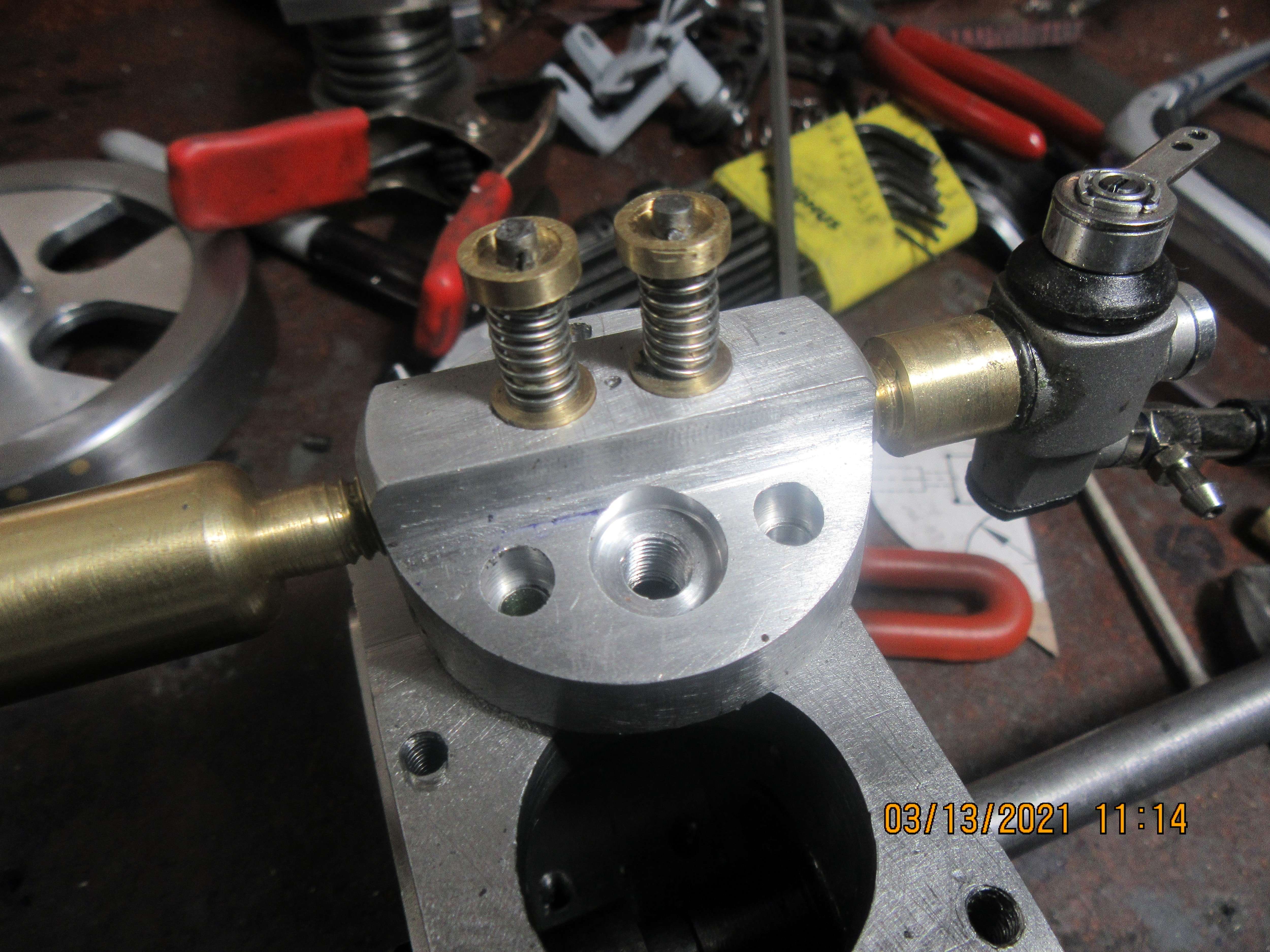
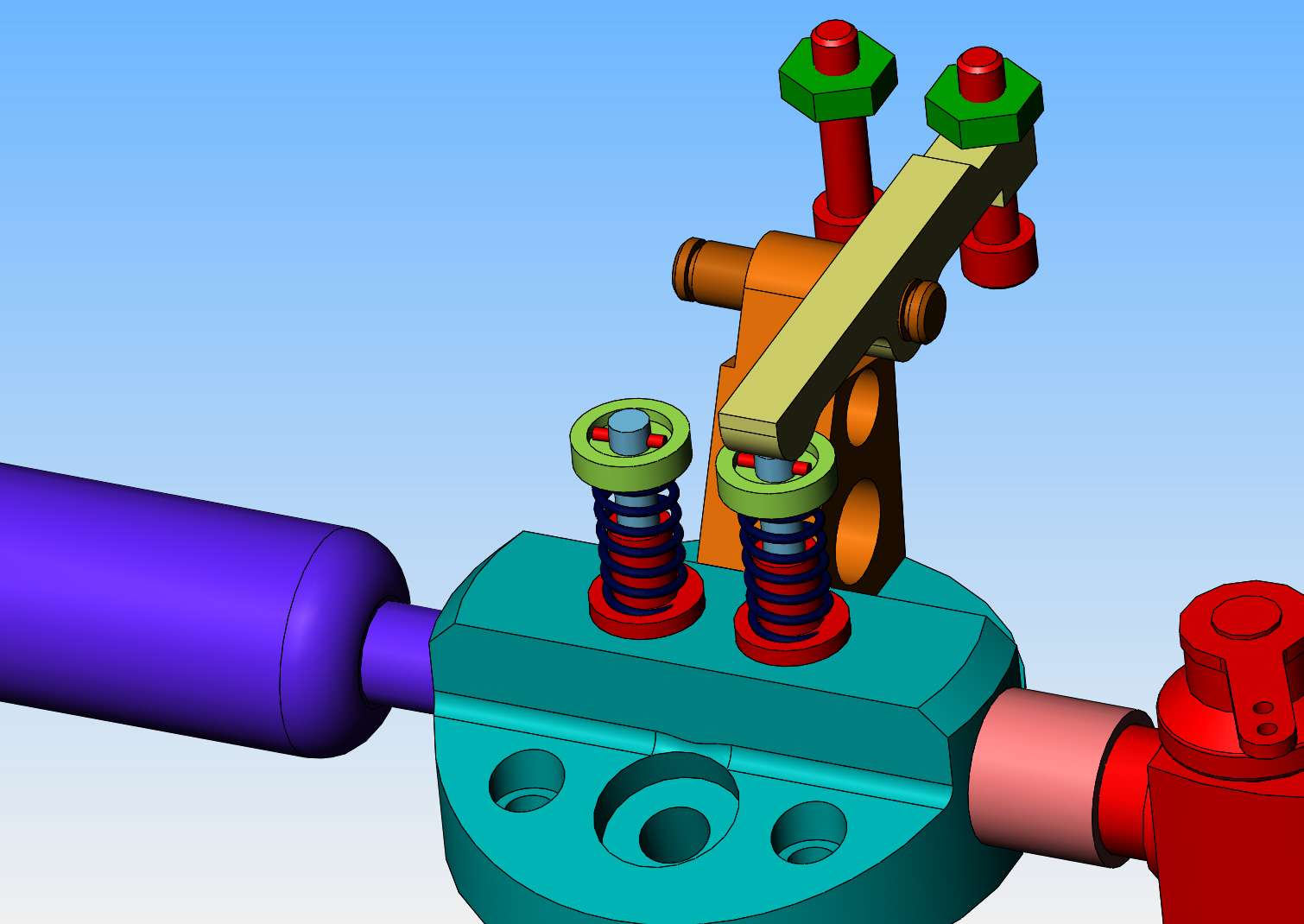
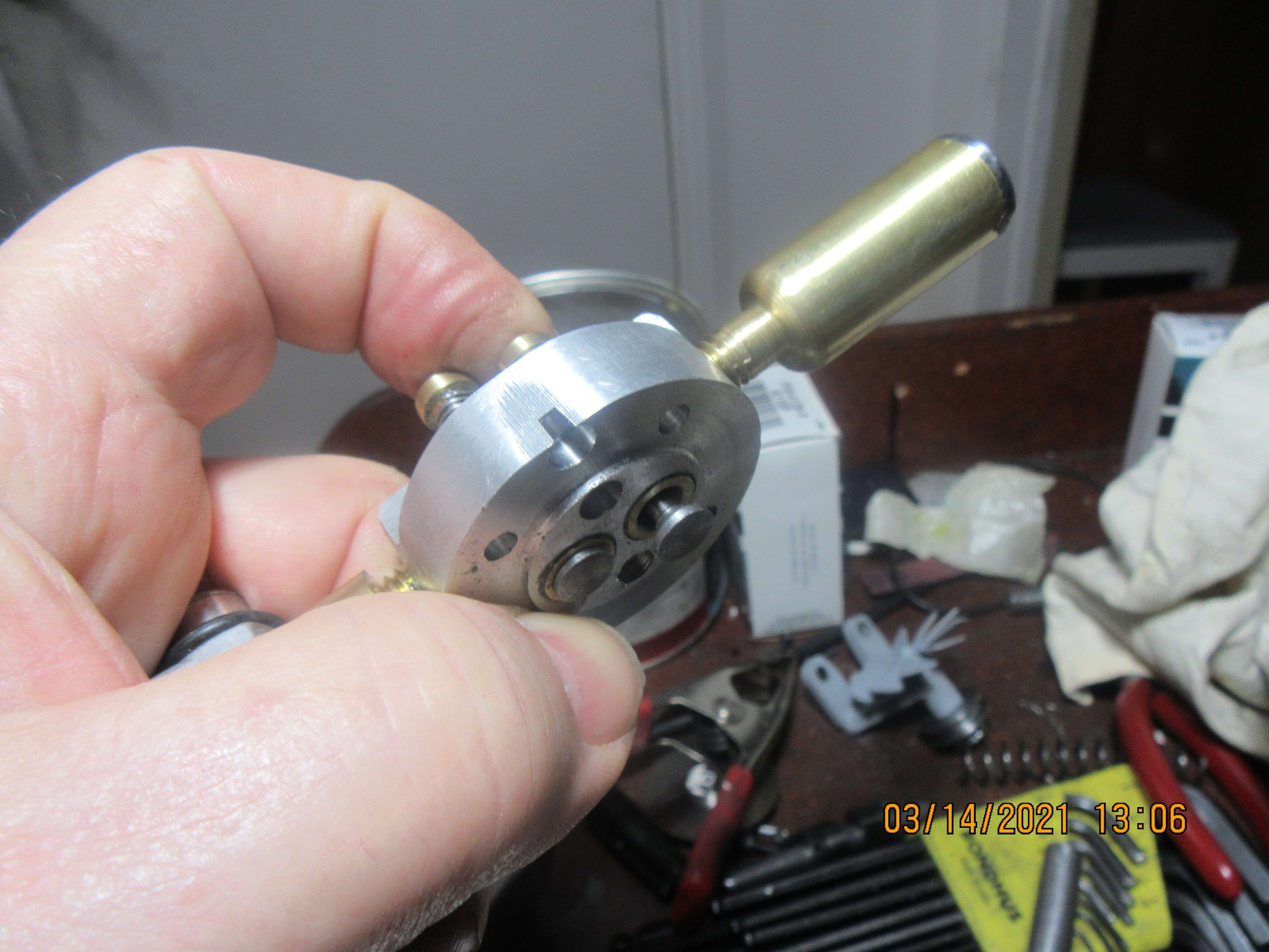
Here we have both valves, valve springs, and spring keepers assembled in the cylinder head. The valves were lapped into the seats first with #320 grit lapping paste, then 400 grit lapping paste, and finally with 600 grit lapping paste. After lapping the valves had the "handle portion" above the taper trimmed off and about .025" left at 5/16" diameter before the taper begins.
QxvRku.jpg

hnwUZM.jpg
 
Brian, I thought you were slowing down?

Don't hurt yourself.

Don't mean to be preachy, but I've seen far, far too many people just getting over an injury re-injure themselves because "it doesn't hurt that bad" and they plunge back to it.
 
CFLBob--Thank you for your concern. I am feeling a bit better, and there is always a good chance of dying from boredom. The work to install the valves and make the keepers was one of those things I could do mostly while setting down.
 
Hey Brian -- you may have covered this already, but what are you doing for keepers on the valve stem ends? The ones that I've dealt with (old Toyotas and even older Chevys) were split cones that engaged with a shallow groove on the end of the valve stem. I can't see successfully scaling that down unless you have Awesome Machining Powers.
 
Tim---End of valve is cross drilled. Valve spring retainer has flange around it. Valve spring retainer pin fits cross-ways thru valve and flange on spring retainer keeps it in place.
CyVy16.jpg
 
This is something worth mentioning---I find that these small, slow running 4 cycle engines work well with a total valve opening of 0.080" to 0.100". This of course is determined by the shape of the cam. It is always a good idea after the valve springs and valves are installed to use a finger to open the valve fully, and assure that the spring will actually let the valve open by about 0.025" more than that. If the spring compresses fully and the valve isn't opening as far as the cam dictates, something is going to bend or break. You will either bend the rocker, bend the pushrod, or (rarely) break the camshaft.
069hjN.jpg
 
With my newly repaired mill, I was finally able to turn my round piece of 1144 stessproof steel into a bar. I swear to God, there is as much work getting the material from a round bar (which is the only shape you can buy) to a piece of flat bar as there is in all the rest of the crankshaft machining. I milled one side flat, then used the bandsaw to cut the other side flat, then used the mill again to machine the third side flat. I haven't machined any of it down to finished size, because I'm trying to machine it in a manner to keep ahead of any bending or twisting of the material as internal stresses are released. 1144 doesn't move much, but it does move.
BNNKuP.jpg
 
The crankshaft is up on the lathe being turned. In this view, I have just finished machining the con rod boss, and the con-rod is setting in place for a trial fit. All of the turning was done with the carbide nosed cut-off tool in the picture.
tvM7YA.jpg
 
The crankshaft is up on the lathe being turned. In this view, I have just finished machining the con rod boss, and the con-rod is setting in place for a trial fit. All of the turning was done with the carbide nosed cut-off tool in the picture.
tvM7YA.jpg

Did that carbide make a nice clean cut? What speed did you go at when you got down to the thickness of the diameter? Did you polish it afterwards?

Oh, woe are we--I forgot till now, it is the Ides of March, the unholy day Caesar was murdered! Also the day after Einstein's birthday.
 
This is something worth mentioning---I find that these small, slow running 4 cycle engines work well with a total valve opening of 0.080" to 0.100". This of course is determined by the shape of the cam. It is always a good idea after the valve springs and valves are installed to use a finger to open the valve fully, and assure that the spring will actually let the valve open by about 0.025" more than that. If the spring compresses fully and the valve isn't opening as far as the cam dictates, something is going to bend or break. You will either bend the rocker, bend the pushrod, or (rarely) break the camshaft.
069hjN.jpg
is it the pictures, r the was seat are extremely over size ??
 
Hey Brian -- you may have covered this already, but what are you doing for keepers on the valve stem ends? The ones that I've dealt with (old Toyotas and even older Chevys) were split cones that engaged with a shallow groove on the end of the valve stem. I can't see successfully scaling that down unless you have Awesome Machining Powers.
Hi Tim, I'll try and answer for Brian, so he can carry-on making and doing his excellent write-ups.
Actually, it isn't beyond the machining skills of most hobby machinists to make split collets - but usually they make parallel collets instead of the tapered collets on full-sized production engines. (Which are designed to minimise material mass and fatiguing stresses). Remember the ""Toyota" et al manufacturers want to guarantee 150,000 miles in 10 years use... that's 3000 hours without failure - so they design and manufacture for valves and collets to be so under-stressed they'll almost never fail in 3 times that life.
A simple rectangular groove 0.020" ~ 0.040" deep in the stem of the valve with simple cylindrical split collets to engage in the spring-cap - a hole counter-bored maybe 0.040" ~0.080" larger than the valve stem clearance hole, with collets to suit, will be perfectly adequate and machinable by most. BUT this engine is so simple and under-stressed that the pin and hole arrangement that Brian is using will be OK - and simpler to manufacture.
Does that answer your question adequately?
Unless I mis-understand why you chose the pin arrangement, Brian? - Keep up the excellent work.
K2
 
@Steamchick : it is utterly irrational, but if I built a model stationary engine, I'd feel bad if I didn't put it to some use where it would have the opportunity to deliver value until it wore out. Even if it was just some "hobby" value, like running the generator that runs a model train track or something.

This is not to be construed as a judgement on y'all -- you guys are sane. I'm the one tetched in the head.
 
This is not to be construed as a judgement on y'all -- you guys are sane. I'm the one tetched in the head.
Don't be too sure of that. Why, after all, four of us who live in this here body, all agree that the fifth one is the only one who is not sane--you NEVER want to talk to HIM!

Also, I agree, even a model should do something like run a generator or a wheat grinding machine.
 
And there we have it boys and girls. A completely finished crankshaft!! It turned out nice, no visible runout. Now I get to hitch up my horse and drive over to the physical therapist to see what he is going to do about my numb fingers and sore wrists.
PDEhTQ.jpg
 
Tim, "You are a better man than I.... " to quote Kipling. I just like to see them running, but do try and add a generator and lamp if possible. But I'm not really into winding generators, so bicycle dynamos are my convenient loads to make them work..... As to powering a railway... any scale.. Wow!
Enjoy.
But my comment wasn't meant to denergrate anything you all do, just a recognition that models generally are made to demonstrate a principle, and such things as precision ground valves and collets for durability are not necessary for the duty cycle of the models. Hence I was defending what I thought Brian's decision for pinned valve spring caps would be.
Sorry if I raised your blood pressure, not my intent.
K2
 
With my newly repaired mill, I was finally able to turn my round piece of 1144 stessproof steel into a bar. I swear to God, there is as much work getting the material from a round bar (which is the only shape you can buy) to a piece of flat bar as there is in all the rest of the crankshaft machining. I milled one side flat, then used the bandsaw to cut the other side flat, then used the mill again to machine the third side flat. I haven't machined any of it down to finished size, because I'm trying to machine it in a manner to keep ahead of any bending or twisting of the material as internal stresses are released. 1144 doesn't move much, but it does move.
BNNKuP.jpg
And there we have it boys and girls. A completely finished crankshaft!! It turned out nice, no visible runout. Now I get to hitch up my horse and drive over to the physical therapist to see what he is going to do about my numb fingers and sore wrists.
PDEhTQ.jpg
And there we have it boys and girls. A completely finished crankshaft!! It turned out nice, no visible runout. Now I get to hitch up my horse and drive over to the physical therapist to see what he is going to do about my numb fingers and sore wrists.
PDEhTQ.jpg
Nice crankshaft Brian!

Though I'm not a machinist, I recently tried my hand at this (first time I tried something like this), using mystery steel from a trailer hitch drawbar, and it worked after I annealed it overnight in the wood stove.

What I would like to know is what kind of band saw you used and how you cut the steel to size. I have a Chinese 4x6 band saw that doesn't seem to like working in vertical mode, so I had to resort to chain drilling to come close to a decent size before I turned it down in the lathe.

The result has, as far as I can tell, about .0015 TIR, so I think I can live with it; otherwise I'll just have another go at it.

Any advice on cutting steel with a Chinese band saw would be welcome.

IMG_20210203_151131.jpg
IMG_20210209_111325.jpg
IMG_20210213_134656.jpg
IMG_20210313_152923.jpg
 
I have an old 16" vertical wood cutting bandsaw to which I added a second jackshaft and pulleys to bring the rpm down to a speed for cutting steel. It works great--I use a 3/4" x 1/16" metal cutting blade. My cuts ae all straight cuts---the blade is too wide to cut curves with.
 
Back
Top