1/5 IHC Famous Vertical Screen Cooled

Home Model Engine Machinist Forum

Help Support Home Model Engine Machinist Forum:

This site may earn a commission from merchant affiliate links, including eBay, Amazon, and others.
Nicely done Jason....as usual! :bow: :bow: :bow: :bow:

Dave
 
Thanks for all trhe kind comments.

Jake, I've actually had your site bookmarked for about six months since I found one of the images on google, it comes in handy for checking details especially as there are no assembly drawings for the model just all individual parts. Have you done any more work on it as there don't seem to have been any photos added lately?

Jason
 
Jason,
After having the bore sleeved I am held up with getting the flywheels and the sub-base bead blasted. My blast cabinet is not large enough to accomodate them so I have been diverting my attention to my Briggs engine projects until I find an alternative. In the meantine I have picked up some parts for the cart and have begun constructing the wooden deck for it. (Progress pages added below). Have you decided what type of fuel you
will run your engine on? I see they used many types of fuels back in the day. My old IHC manual shows they used Gas, Gasoline, Naphtha, Kerosene, Distillate or Alcohol.
--Jake
Here is a page I added on the flywheels:
https://sites.google.com/site/ihcfamous/page-2/ihc-famous-3-hp-flywheels
Here is my most recent progress on the cart:
https://sites.google.com/site/ihcfamous/page-2/ihc-famous-3-hp-flywheels/ihc-famous-hit-miss-engine-cart
 
I'm going to try either Gasoline or Colman's white gas, I would prefer a liquid as it seems a shame not to use the fuel pump. If it does not run well on those then propane will be the next choice, it is supposed to coke up the small model ignitors less.

Jason
 
Coming along very nicely Jason. I also like to run on liquid fuel and have had fun in the past with the ignitors. Was thinking of trying propane on the Rootsy to see what difference it makes, please post if you try it also.

Cheers,
MartinH
 
Jason
You might want to experiment with a Vapor Foam carb, while you are playing with it. I run one with Coleman fuel and it's super easy to start and adjust. Super simple design and much less finicky than a needle valve carb. They look cool too....LOL

Steve
 
Is it really almost six months since I last posted here? Better get on and update you with progress.

The rocker arm is supplied as a casting but its not upto much and the amount of work to try and get it to look like the finished item would probably be more than fabricating so thats what I went for. The four main parts were machined up

PICT0189.jpg


and placed on a jig to hold them in place then coated in correction fluid to stop the silver solder sticking it all together.

PICT0194.jpg


Looks a bit of a mess after heating

PICT0196.jpg


But after a dip in acid and some emery cloth starts to look like a forging. I would like to say this was how it turned out but the first one when offered up to the engine revealed that the two critical dimensions were transposed on the drawing so the end of the rocker arm missed the top of the valve and the pushrod hit the cylinder, yet another drawing error.

PICT0329.jpg


While set up for fabricating small parts the fuel pump actuating lever was also done as a fabrication, there is no roller or pivot shown on the drawings so made it up ::)

PICT0334.jpg


Also did the latch out lever which was fun with all the curves and angles, works OK but did need a bit of cold setting after soldering up. The little roller runs against the angled rim of the spool.

PICT0332.jpg


And the last lever needed is the one that operates the pushrod and closes the fuel pump. The little plate at the end is what the latch out lever catches on. Again more errors the roller is shown reamed 1/8" but the rod has a 3/16" hole so you would either have a very sloppy fitting pin or have a job driving a 3/16" one into an 1/8" hole :p


PICT0333.jpg


cont'd..
 
I like what you are doing here. Opens up all kinds of possibilities. Nice work!

Chuck
 
After all that fabrication a bit of machining was a nice change of pace, so the timing gears were tackled next.

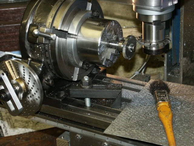
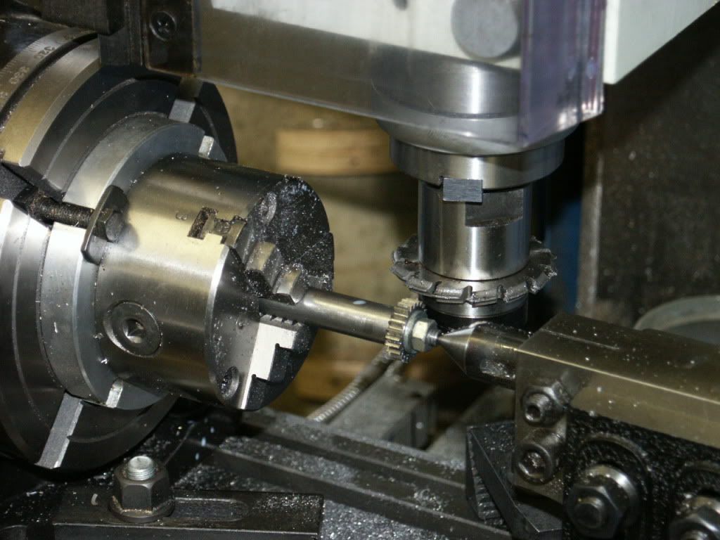
The blanks were turned & bored and then mounted onto an arbor so the teeth could be cut on the mill. big gear underway

PICT0229.jpg


And the little one on a longer arbor so the cutter would miss the chuck, which needed the centre to stop the large overhang deflecting.

PICT0233.jpg


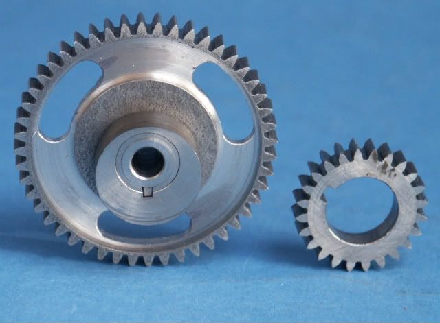
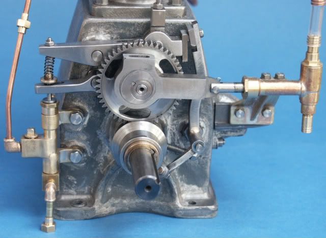
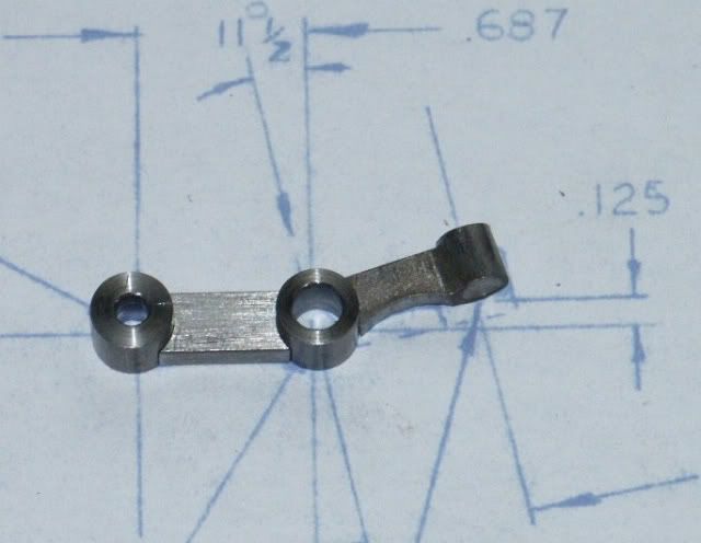
The guy that I am making this for sent me some photos of a full size which showed up some shortcommings on the drawings. One was that the gears are shown as just plain discs, infact the large one is thinner in the centre and also has 3 slots so these were added along with the keyways. The water pump eccentric is also shown in this pic

PICT0330.jpg


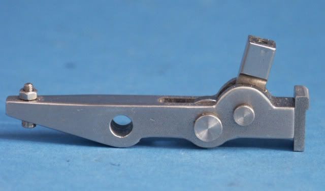
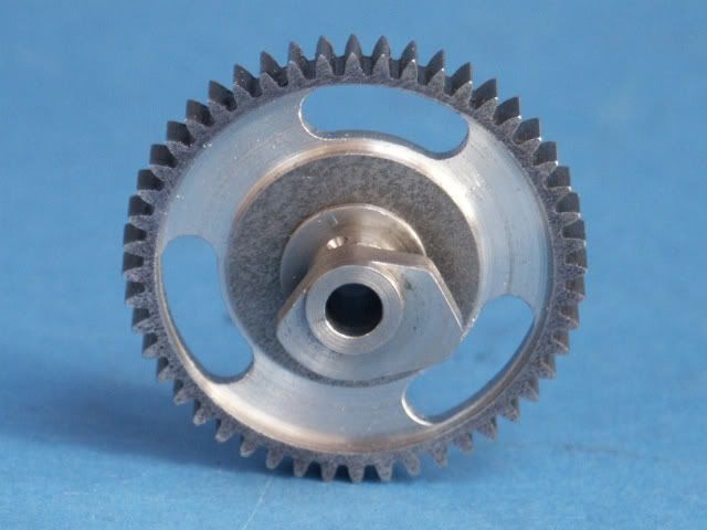
and the other side shows the cam profile cut, I did a test run in alloy to make sure this bit was OK

PICT0331.jpg


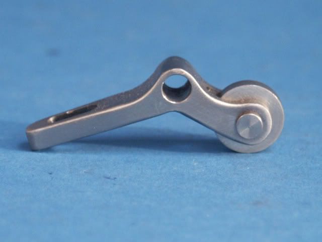
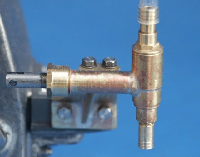
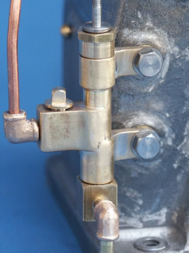
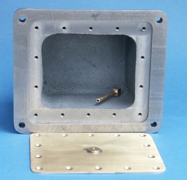
Then it was back to fabrication of the waterpump. this is nothing like what the drawings show I based it on the photos and am far happier with the result, just need to find the right black hose as the clear is wrong but it helped to see that the pump was working OK.

PICT0336.jpg


Same applies to the fuel pump and plumbing all based on the photos of the full size

PICT0337.jpg


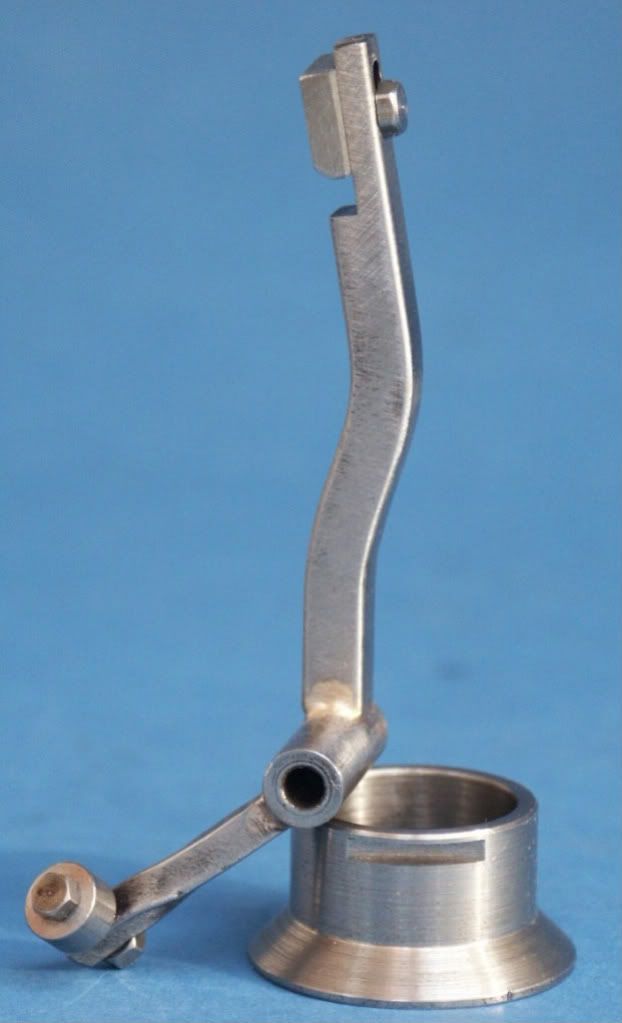
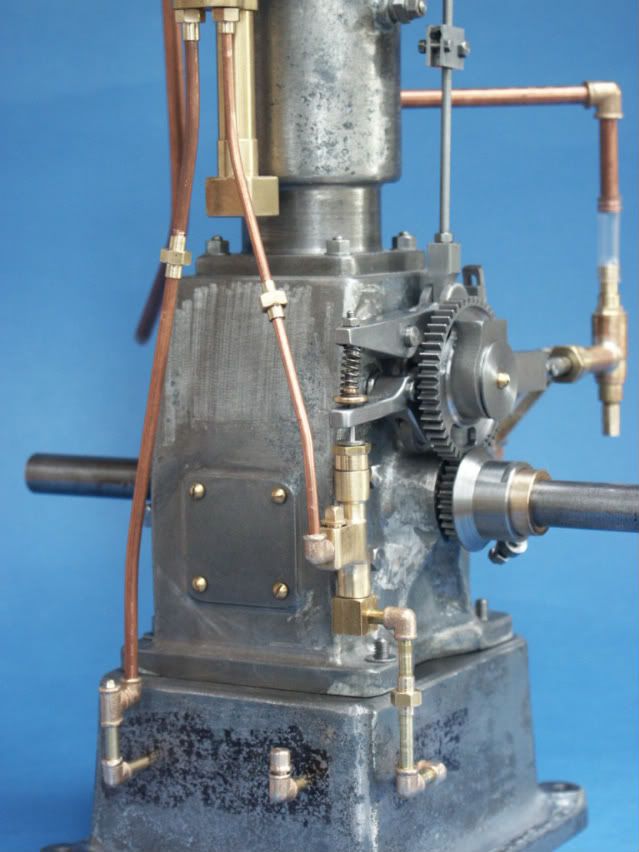
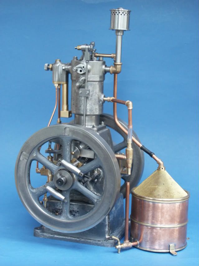
Well thats enough for tonight but I will leave you with a photo of how all these bits go together, more to follow in the next day or so.

Jason

PICT0338.jpg


You are doing great work. One of the interesting things I see is the great difference in relationship of the cylinder bore versus the size of the flywheels, when compared to the Kerzel hit and miss engine I built last winter. Although my engine runs well, it doesn't give the same hit/miss cycles that you get with a full size hit and miss engine, and I strongly suspect that the flywheels are undersized to give that effect. I will be very interested to see yours run.----Brian
 
Wonderful job
I'll be following along for sure
Pete
 
The drawings show a small brass fuel tank that fits into the engine base but as I wanted to use the correct pipework & fittings this would have been a bit hard to plumb up. I decided to mill a recess around the base and fit a brass plate thus making the whole base into a fuel tank, this will be sealed with an epoxy when I know no more work is needed on that part. The small boss in the middle of the plate will take a valve to allow the tank to be drained

PICT0339.jpg


It was then a case of plumbing up the fuel system, 1/8" feed to pump, 3/32" pump to carb, 1/8" gravity return from carb to tank and 1/8" filler. All together there are 38 parts in the fuel lines - pipes, elbows, unions etc.

PICT0341.jpg


As the title of the thread suggests this is a "screen cooled" engine where the water is pumped over a mesh screen which acts like a radiator. Again looking at the photos I saw that the screen appeared to have a rim around it. Not having a suitable bit of 3 1/8" dia brass in stock I bent a bit of 5/16 square around a suitable former and silver soldered the ends together then machined the ring out of it.

PICT0342.jpg


The drawings have the water tank as a plain bit of 2" dia tube 1 1/2" tall soldered to a square plate. This is nothing like it should be. I went for 3" dia x 2 3/4" high, separate feet and also added some half round beading to replicate the look of the ribs you get round oil drums and the like. Just needs a scale galvanized finish.

PICT0343.jpg


And this last shot is where I'm upto at the moment. Just got to finish the ignitor, make an oil level gauge as the crank is wet lubricated and make a scale drip feed oiler for the cylinder.

PICT0344.jpg


Jason
 
Excellent work there Jason. The extra touches like the beading add so much to the tank. I think going a little bigger is a plus. If it was made smaller and didn't cool enough you would have to remake it.
gbritnell
 
absolutely magic :)
 
This is a really beautiful build that is full of character. I cant wait to see it finished and running.


Tim
 
Such a great looking engine and the level of detail is perfect. Theres nothing nice than proper copper pipework with cast joints. Im intrigued to see the timing mechanism working, somehow reminds me of a can opener ::)

Do you use ordinary 'tipex' type correction fluid when silver soldering?? I have never tried this but it looks like it works very well.

Rob.

 
Actually all the pipework will be painted, no place for bling on a scale model for me. It would just be steel "barrel" with malable iron fittings on the full size, its just not easy to get steel in those sizes so I used copper/brass.

Yes just standard tippex stops the solder sticking where you don't want it.

Thanks for all the other comments guys.

Jason
 

Latest posts

Back
Top