1/5 IHC Famous Vertical Screen Cooled

Home Model Engine Machinist Forum

Help Support Home Model Engine Machinist Forum:

This site may earn a commission from merchant affiliate links, including eBay, Amazon, and others.

Jasonb

Project of the Month Winner!!!
Project of the Month Winner
Joined
Mar 30, 2008
Messages
3,767
Reaction score
1,239
Location
Surrey, UK
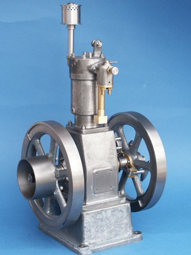
I've recently started on this model of an IHC Famous Engine, the castings are the original May Engine Works ones and have been through the hands of at least two members of this forum before being purchased by their current owner who I am building it for.

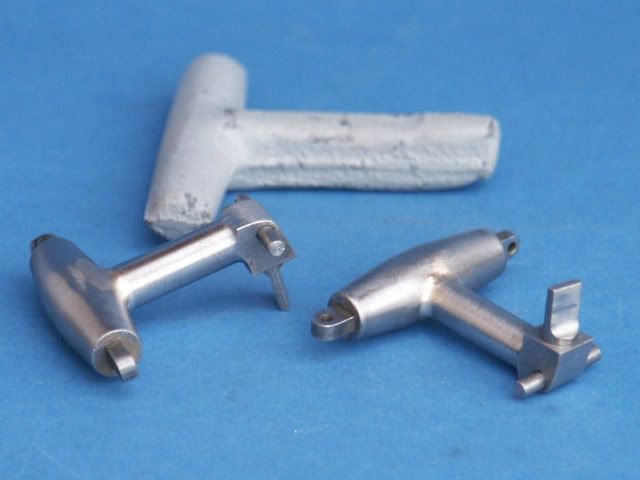
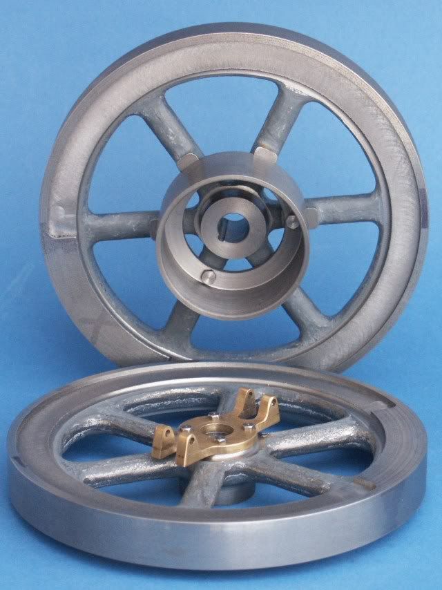
The kit contains 18 castings, 16 in iron and two in gun metal as you can see below, one of the previous owners had painted them in two shades of grey paint.

Famouscastings.jpg


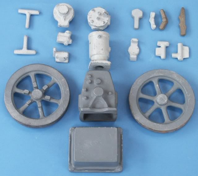
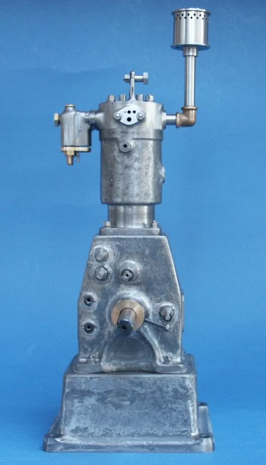
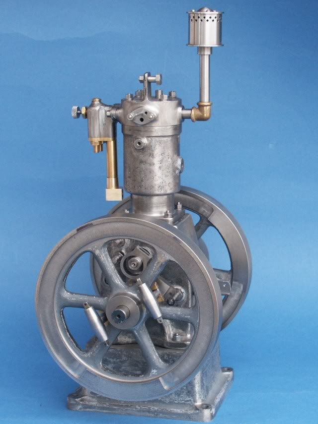
As an idea of size the flywheels finish up around 5 1/2" dia and the engine about 12" tall

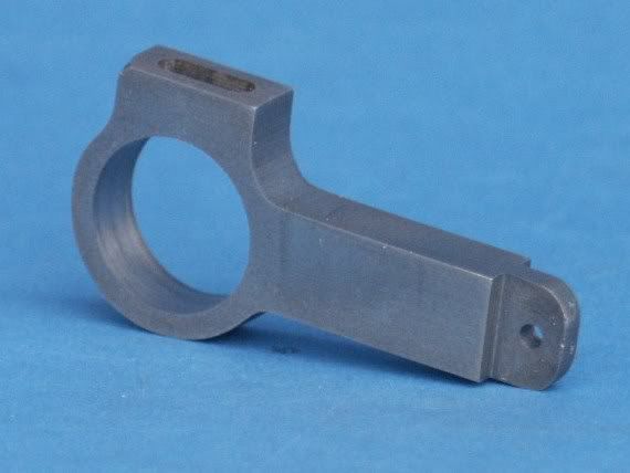
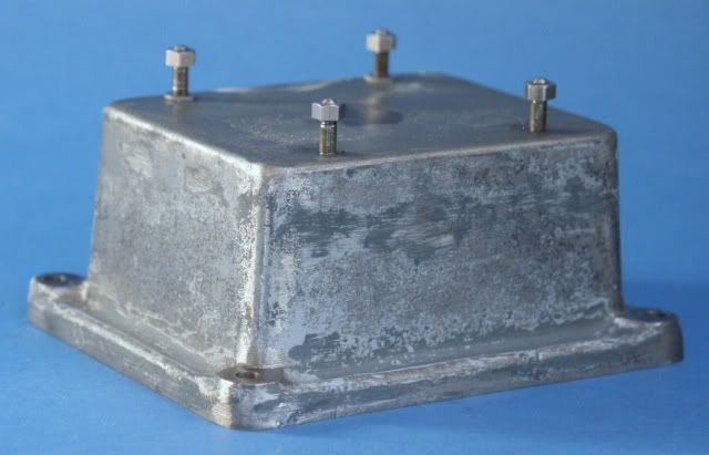
The first part I tackled was the base casting, as the sides are tapered it was not going to be easy to hold so I shimmed it up on the mill and machined the top surface and tapped the four holes. I then drilled matching holes in a bit of flat alloy bar and used CSk screws to join the two, it was then a simple case of clamping the flat bar to the table so I could machine the bottom of the casting.

Base.jpg


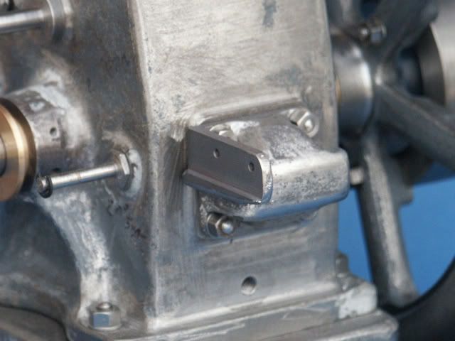
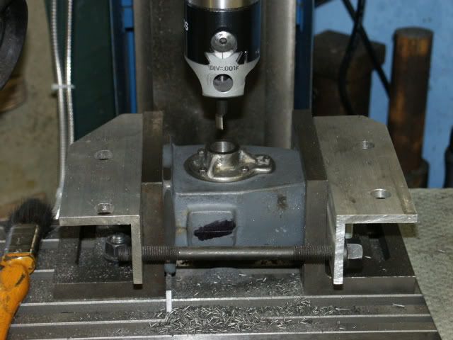
Next on the list was the crank case, again I machined the top then bottom and took a light skim around the 4 edges of the base flange so I would have 4 true edges to setup the casting with. I mounted it on its side between two angle plates and it was just a case of rotating 90degrees and then machining the next face.

boringbearing.jpg


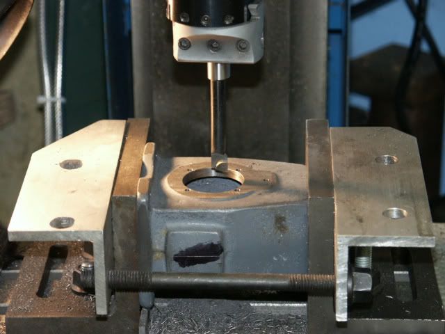
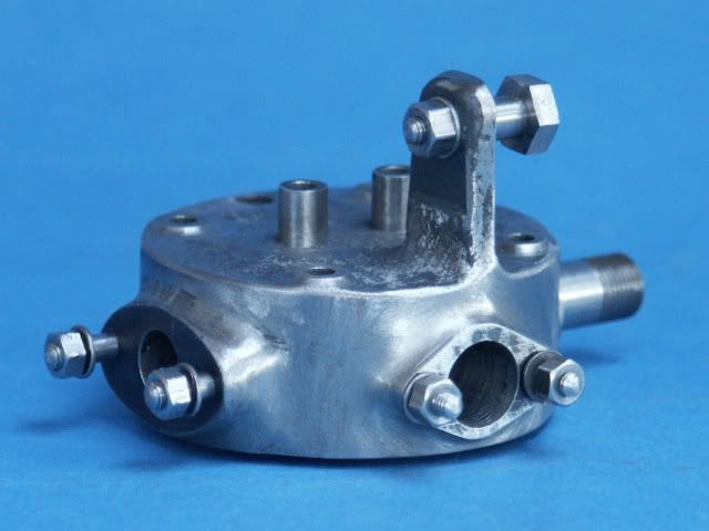
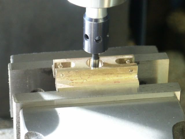
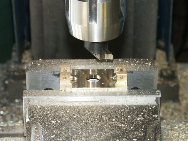
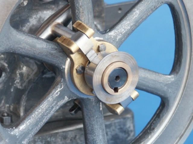
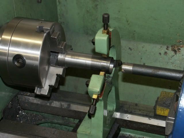
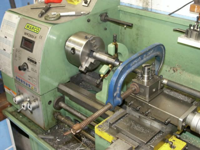
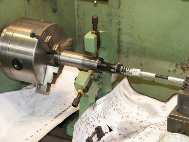
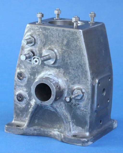
I mounted the bearing carrier into the casting so I could bore that at the same setting as the fixed side to make sure all was in line.

Bearingcage.jpg


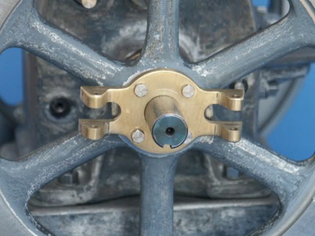
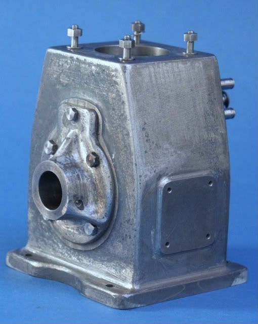
And here it is with a few pivot pins fitted

Crankcase1.jpg


Crankcase2.jpg


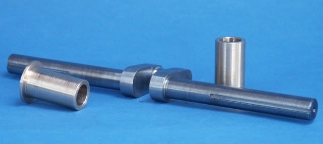
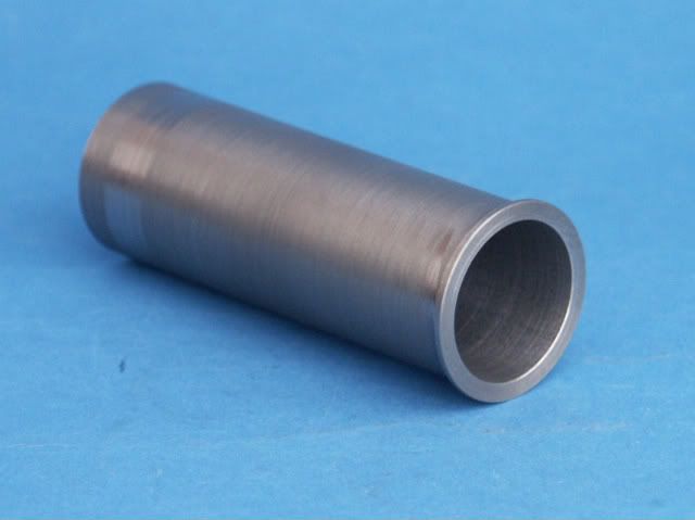
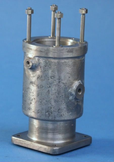
The cylinder was a fairly straight forward boring and then drilling job followed by a bit of fettling with the Dremel around the various cast bosses

Cylinder.jpg


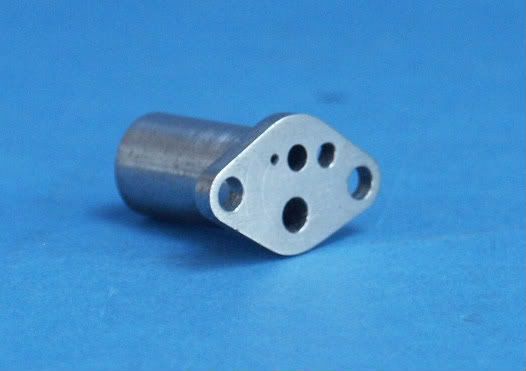
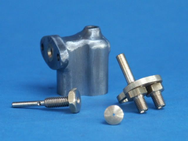
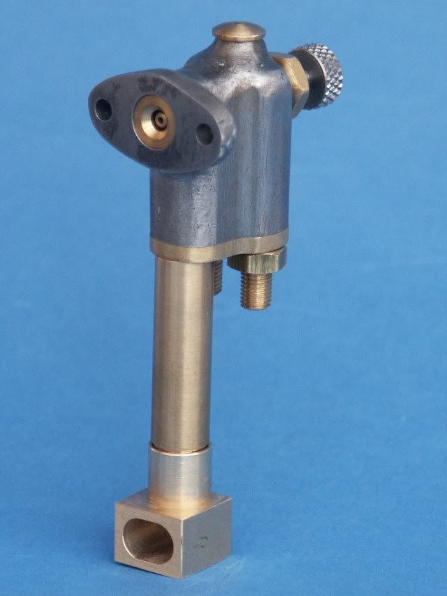
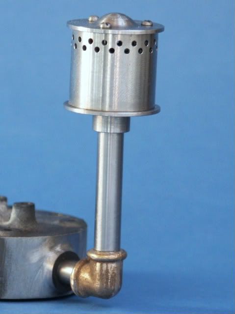
Finally for a change of material I did the Muffler parts, the cast elbow was from PM Research

Muffler.jpg


Jason
 
That is looking great Jason. You have made a lot of progress so far and it is going to be a fine looking engine! Looking forward to seeing more.

Bill
 
Yes, by all means, looking very nice. Guess it's safe to say that the nuts and studs are home brew. :bow:
 
Jason,
Beautiful work. Also, thank you for showing the set up and machining sequence for the castings. I hope you'll keep doing that. How one makes those first cuts on a casting has always been a mystery to me, so any tips are greatly appreciated.
Dennis
 

Nice work Jason!

I haven't seen many engines made from casting kits. This will be a good one to follow along.

Nice photo's too.
 
Well I think its time for an update on progress.

Working from the bottom up the next logical part was the cylinder head which is an iron casting split horizontally and with about a 1/16" mould shift between the two halves :(
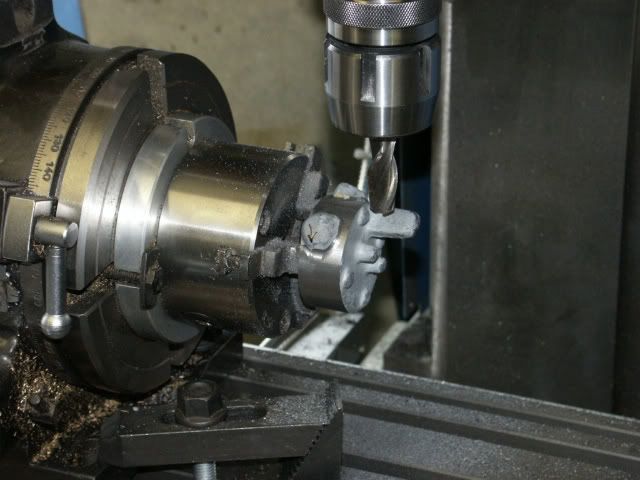
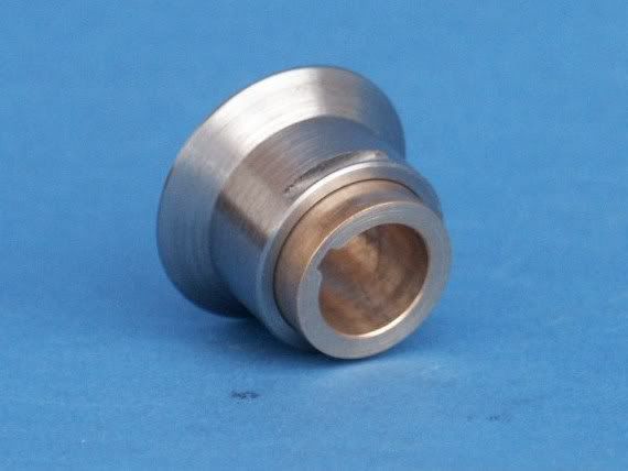
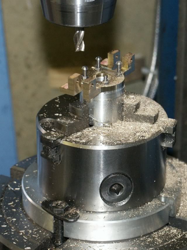
. Luckily there was a good machining allowance on the spigot that fits into the cylinder so that was turned first and used to hold the head in a chuck on the rotary table so the stepped casting edge could be sorted out, this took 180 passes at 2 degree intervals while working around the cast bosses.

TruingHead.jpg


Before I could tidy up the bosses I wanted to do the mating parts, first the Ignitor body which was fairly straight forward turning, drilling and milling

PICT0134.jpg


The carb followed, this again had mould shift and is not an easy item to hold so the flange and mounting holes were machined first so it could be screwed to an alloy block which gave me something to get hold of while machining the many internal cavities and passageways. I did a few of the associated parts at the same time.

PICT0135.jpg


The bosses were then tidied up, rather than describe it again I talked about them in this thread. The top of the head was then machined, unfortunatly the post for the rocker arm was chilled and blunted a 1/2" mill, 10mins at read heat and a slow cool sorted that out :) and the head was complete.

PICT0133.jpg
 
For a change from castings I tackled the crank next. This is just a silver brazed fabrication and I also pinned the joints after soldering so it should be bomb proof, then profiled the webs and milled the 3/32" keyways. The bearings are just simple turning from SA660 bearing bronze the only problem now is that with the bearings installed I have a 7/8" gap to take a 1" wide crank ???

PICT0132.jpg


And this is where I'm at, well there are a few other bits part way through, needless to say more issues with chilled castings but that will have to wait for another day.

PICT0131.jpg


Jason
 
Jason, this is coming along very well indeed. Its looking more and more like the real thing. I am assuming that the castings are no longer available...is that correct? Keep up the fine work...this is going to be a beauty!!!

Bill
 
Thanks for the comments guys

May Engine Works sold it to Blackberry, then sold it on but the guy who has the patterns is not doing anything with them at the moment.

Jason
 
Unfortunatly this engihe is not available at the moment, mine is from original May Engine Works castings, it was then produced by Blackberry models who have sold the castings to someone else who is not doing anything with them at the moment.

It would be possible to make this engine without castings, I feel all the cast parts could be fabricated and I will be fabricating a few of teh smaller castings that are not usable. As I'm making this engine for someone else I will be making one for myself by fabrication in 1/4 scale, infact I started making the base "casting" this weekend, watch out for a new post covering the build.

Jason

PS PM sent
 
Jason, I look forward to details of your 1/4 scale build. The IHC Famous has always been one of my favorites.

Chuck
 
Jasonb said:
And this is where I'm at, well there are a few other bits part way through, needless to say more issues with chilled castings but that will have to wait for another day.
PICT0131.jpg


Jason

Looks like a surprised alien about to throw a WW2 hand grenade... :big:
 
This seems a good time of year to catch up on progress on the Famous.

The Carb is now complete, the stailess steel needle valve has been done as have the air pipe and inlet elbow, both in brass. You can also see how the venturi is set into the casting around the jet.

PICT0163.jpg


The governor spool is turned from steel and slides on a bronze sleeve that is keyed to the crankshaft. The governor arms engage in the two small slots and the actuating arm has a roller that runs against the angled face.

PICT0165.jpg


The carrier was once again an iron casting that was hevily chilled and moved while I attempted to machine it as the tool was pushed off the hard bits, only option was to make a new one. Unlike Metalbutcher I decided to silver solder two bits of brass together as the basis of the part. This first picture shows me picking up the centre after the "T" shaped fabrication was turned over in preparation for machining out the middle

PICT0126.jpg


And the middle being taken out with a small flycutter as I wanted a radius fillet to the internal corners

PICT0129.jpg


The four mounting holes were drilled at the same setting and then used to hold the job onto a suitably tapped bit of alloy in the rotary table so the external profile could be milled

PICT0130.jpg


And this is the finished carrier after a bit of filing

PICT0167.jpg


Cont'd
 
Two castings are supplied for the governor weights, these had too much mould shift to be of any real use and I suspect they would be chilled like the rest of the small CI parts. So I fabricated them from 3/8" dia steel for the actual weight and 3/8x1/4" flat stock for the arms. The two pins have a flat in the middle and the thread of the tangs locate on this to hold the pins in place, casting in background.

PICT0169.jpg


I have slipped the assembly onto the crank back to front so you can get an idea of how it works

PICT0166.jpg


Two other Iron castings were salvagable after a long blast with the propane torch, they are the breather box and water pump eccentric strap/arm

PICT0168.jpg


PICT0164.jpg


The flywheels were straight forward turning and boring jobs done on the faceplate. The balance weights have to be formed by milling away the rim for 300degrees each side which was done on the rotary table. The drawings don't show one but I added a pully as it would be nice to se the engine doing something.

PICT0170.jpg


Cont'd

 
While the lathe had cast iron swarf over it I decided to tackle the last couple of parts that were from the same material.

The cylinder liner was machined from a 3 3/4 length of 40mm cast iron bar, this was roughed out .060" oversize and left for a week before final machining, the outside first then I added a fixed steady when machining the 1" bore with a 3/4" boring bar.

PICT0156.jpg


Note the hi-tec tool holding device ;)

PICT0157.jpg


The bore was machined .002" undersize and then finished with a sprung hone using parafin (kerosine) to stop the stones clogging. The hone was held in the toolpost so the carrage could be easily moved back and forth, paper to keep any abrasive off the machine

PICT0158.jpg


And the finished item with the top lip reduced to the correct size, I left it oversize to give me something to hold while boring.

PICT0174.jpg


I used a bit of the same cast iron to make the piston rings, here they are being parted off along with a few spares

PICT0160.jpg


The piston had already been made so I completed this section by doing the conrod and bearings

PICT0172.jpg


Well thats about it all upto date so I'll finish of with a couple of shots of the current state of play.

PICT0175.jpg


PICT0176.jpg


Jason
 
Jason,
that is a sweet looking engine, nice work.

Randel
 
Jason, Great looking build, really waiting to see this one run. larry
 
Jason,
Excellent machining work on your engine. There are so many horizontal hit and miss engines out there it's nice to see something different.
Having worked in the casting industry for many years I'm really dumbfounded when I see parts like your governor weights. What's the sense in making a casting if you have to machine the whole thing and then to not anneal it so that it can be cut.
I am working on an engine with some of the same casting problems so I know what you're going through.
gbritnell
 
Back
Top