1/4 Scale Gnome Rotary

Home Model Engine Machinist Forum

Help Support Home Model Engine Machinist Forum:

This site may earn a commission from merchant affiliate links, including eBay, Amazon, and others.

cwelkie

Well-Known Member
Joined
Dec 19, 2010
Messages
170
Reaction score
60
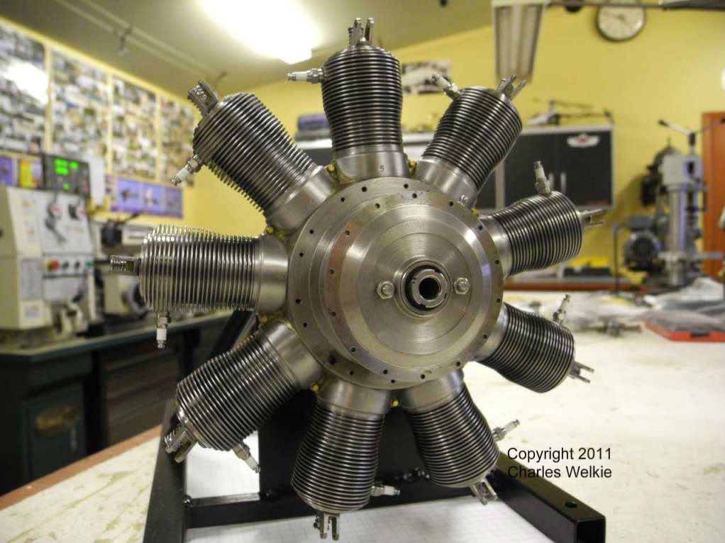
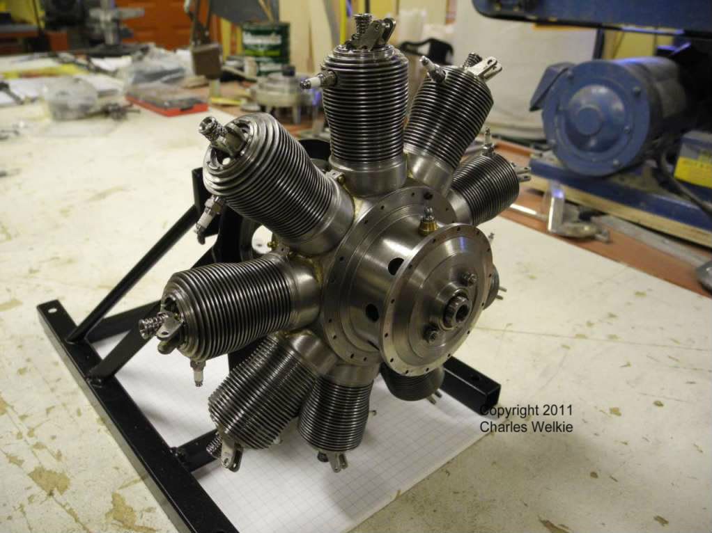
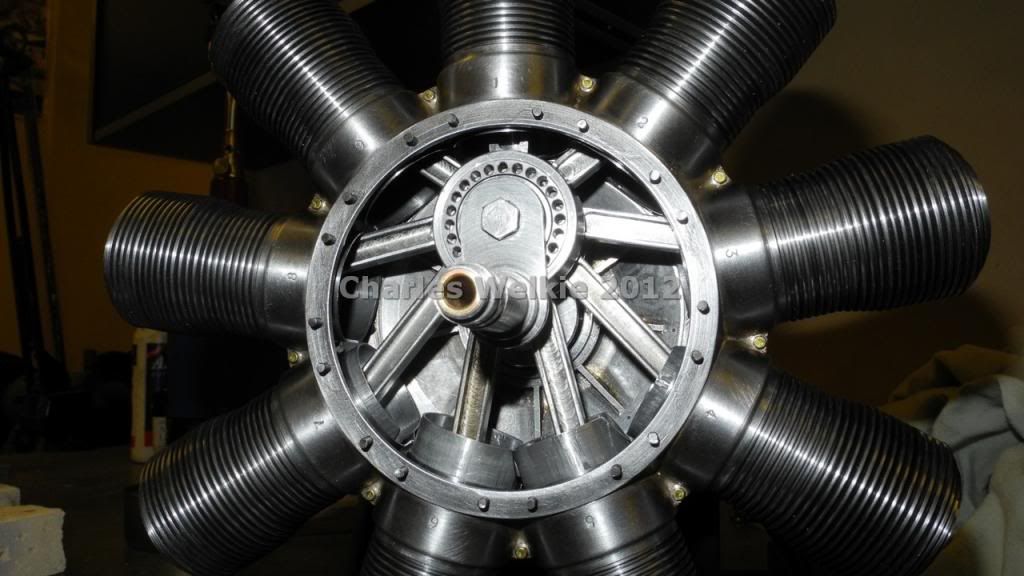
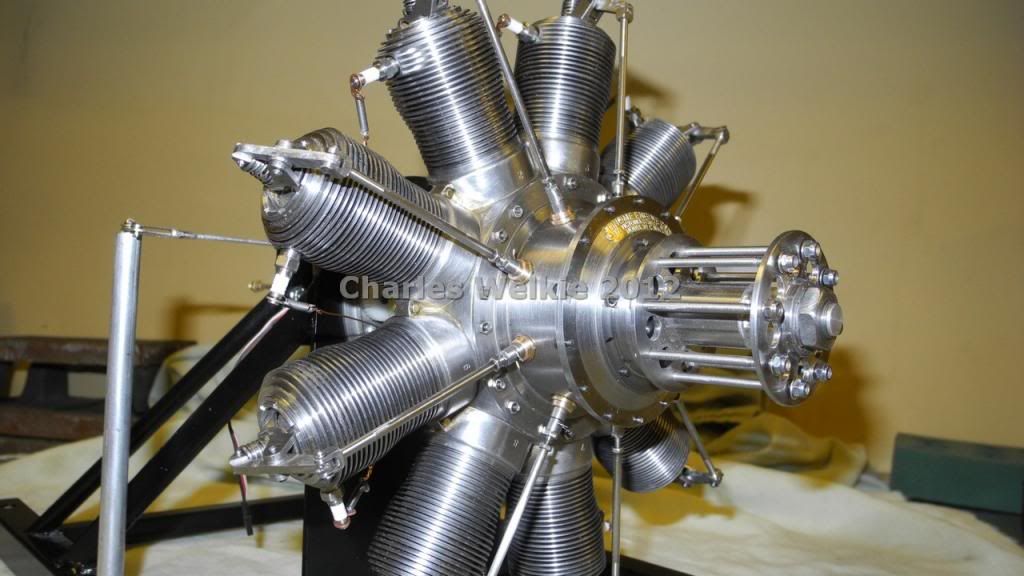
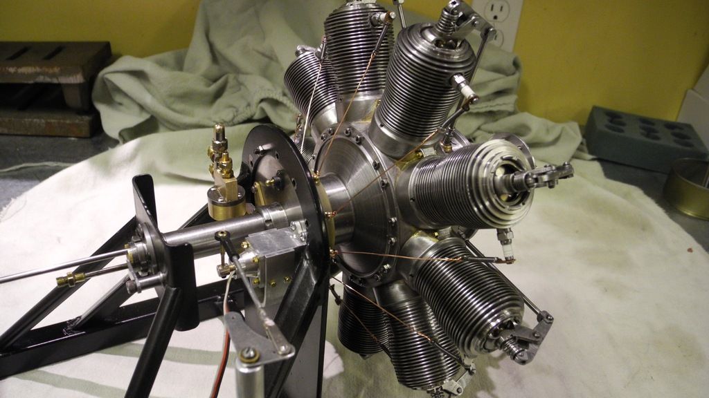
Many of you have already seen some photos of my current build - a 1/4 scale Gnome built from Stephen Wessel's excellent drawing set for a 1/3 scale version.

Just thought that you might like to see some of the recent progress ...

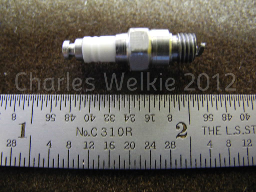
First - one of the spark plugs. Corian insulator with a 10-32 thread. (Sorry - I should have held the camera focus on the plug ...)

SparkPlug.jpg


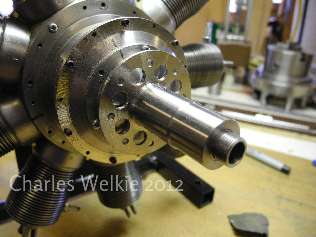
The propeller hub - still without it's splines for the "washer". (Need to make the broach before I'll be happy cutting the splines into the hub.)

PropHub.jpg


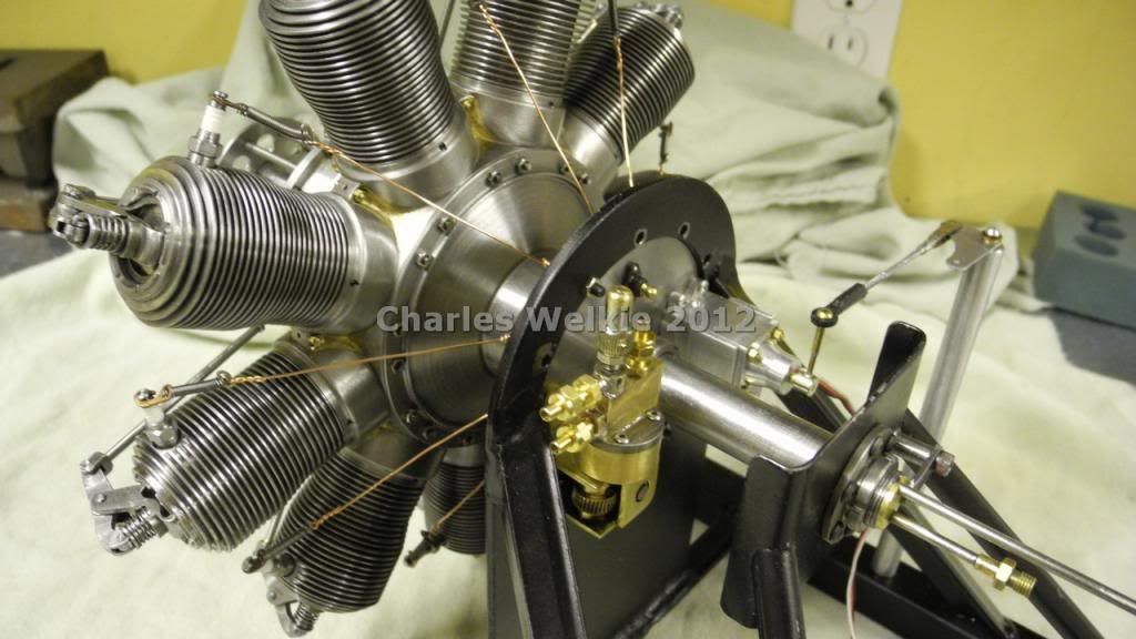
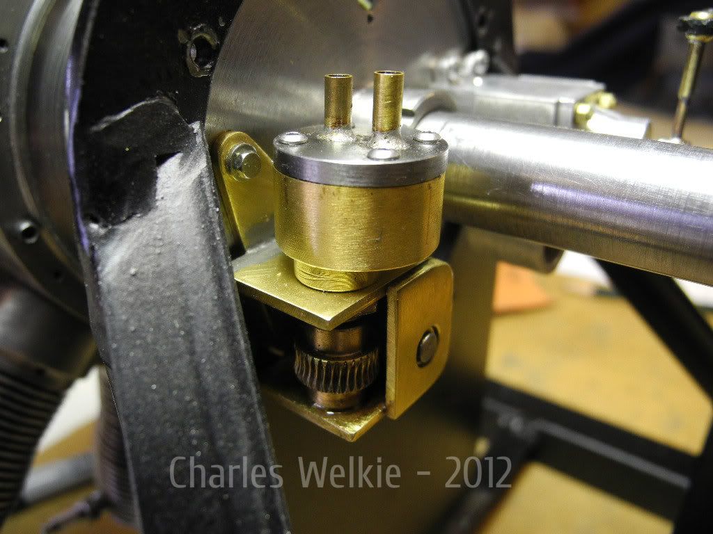
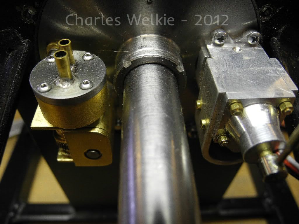
The oil pump. Not scale but very functional - typical gear pump driven off the accessory drive via a worm gear

OilPump.jpg


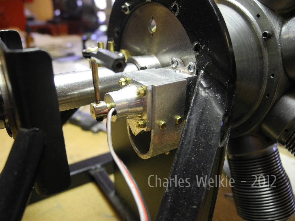
The dummy magneto. It houses two magnets on a rotating disk and an adjustable mount for a hall effect sensor

Magneto.jpg


Both rear accessories together (Yes I know - the Phillips screws must go!)

Accessories.jpg


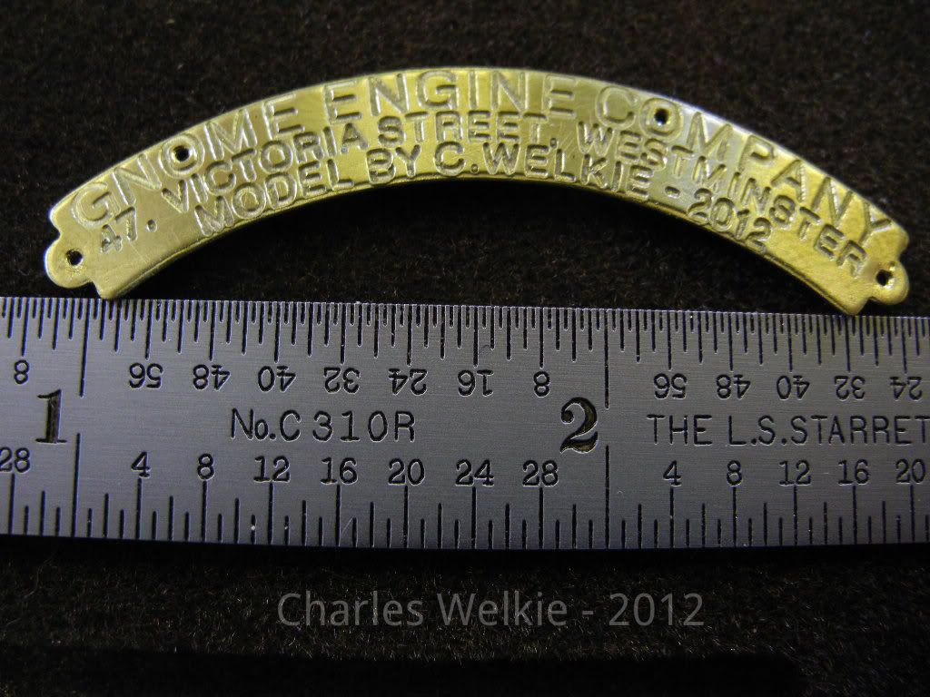
Now the nameplate. It fits to the front crankcase cover under #1 cylinder. Sorry for the cross-post ;) ... It was engraved on my homemade cnc router.

Nameplate.jpg


That's it for now.
Charlie
 
Very nice Charlie. As Steve said, can you post some photos of the whole engine.

Vince
 
Thanks for the kind comments guys ... here are a couple more photos that aren't on the site already.
Sorry - this don't show the pushrods, rockers and tappets ... and I really feel like re-installing them (again) for a photo. (I promise - next time they are installed!)

DSCN0719.jpg


DSCN0716.jpg


Cheers
Charlie
 
cwelkie said:
...one of the spark plugs. Corian insulator with a 10-32 thread... Charlie

Very impressive Charlie. I cant wait to see it run one day soon.

Q1) The spark plugs are borderline jewelry! Is it your own design or part of the Wessel plans also proportionately scale it down a bit to suit your 1/3 > 1/4 overall scale reduction? Is there adhesive used between the corian & metal parts? If so what is used? Any special metal on the right angled (electrode?) part?

Q2) I'm eyeballing your fins & they just seem so nicely scale (ie thin). Can you give me an idea of the width & depth dimensions & how you achieved that?
 
Thanks Peter ... The day it runs will be monumental indeed. I'll let you know when to stop by!

The spark plugs can hardly be called "my design". They are a compilation of ideas and design elements from many articles both online and in print. They most closely resemble the Rimfire Z3 in dimensions though. I did use - hold the laughter please - JB Weld (the older formulation). After some research into affordable and readily available adhesives, it held the best promise for standing up to some heat. It was a bit of a bear to get just enough in place without overfilling the space but it did work out. Time will tell. For extra, insurance the top of the metal body is also swagged to the insulator. No special metal alloy. The ground electrode was machined from the body after boring out the inside dimensions. (Yes - bored ... I love those tiny carbide boring bars from Micro 100!)

The fins are 0.030" (nominal) with o.040" spacing. The deepest ones are in almost 0.3". I used 12L14 (leaded steel) for the cylinders and am glad I did after cutting the fins ... it actually went quite well. (There are just sooo many of the them.) I simply used a regular, thin cutoff blade with a hollow ground edge. I constantly applied straight cutting oil throughout each cut. It turns out that the CA glue tips modelers use fit on the cutting oil can spout perfectly! The tiny hole in the applicator tip metered out just the right amount of cutting oil.
 
Very nice work Charlie. I'm really looking forward to seeing and hearing it running.

Vic.
 
Absolutely stunning what else can i say.I have used the old formulae JB Weld for making rim fire plugs running small hit and mis engines without any problems but they do run pretty cold.
best wishes Frazer


Absolutely marvolous!! :bow: :bow:

I have plans for a Edwards Five Radial, but this is a different league altogether.

Well done.

Ron
 
Hello everyone! Merry Christmas and Happy New Year!

It's been some months since I've updated this thread and thought it time to share a few more photos by way of an update.
I daresay that the engine is assembled! (Now that I've written that, I'll inevitably be taking at least some of it apart again ... oh well.)
Now I'll have to get on to the support and auxiliary equipment required. Things like a controls panel and fuel/oil tanks.

Assembly has to begin somewhere ...
Begin_zps0fa75be6.jpg


The first few crankcase holes filled:
LowerCrankcase_zps8fc658f8.jpg


All the crankcase holes filled:
FullCrankcase_zps8ad6399c.jpg


... and the rest of the bits in place:
RightFrontDec12_zps98ca5769.jpg


LeftRear2Dec12_zpsbbcd387b.jpg


RightRear2Dec12_zps041b7ef6.jpg


Thanks for looking in ...
Cheers,
Charlie
 
The Gnome is a really nice engine!
And your model is even nicer!


Nick
 
Beautiful work Charlie, coming along great. I can't wait to see it run. If you ever find yourself out Calgary way, please stop by for a visit. Oh.. and bring the engine! :)

Can you elaborate on the link rods & master rod assembly a bit. They look they like might be made of steel? Do they use bushings on either end? Any cross/bleed holes for lubrication to the wrist pins, or how does that work on rorary's?
 
Hi Charlie
Wow That is just lovely
Pete
 
Thanks Nick and Pete.

Peter, good to hear from you. Thanks. If ever I can be convinced to cross the "Great Divide" I'll bring the Gnome along ;o).

Yes, the rods are steel with bronze bushings at each end. The oil supply runs through the crankshaft all the way to the front cam pack (drilled, cross-drilled and plugged as appropriate). The crank is drilled to supply the lower end of the rods. The lower rod end is drilled to allow oil in and then out again so it can run up the length of the rod on both sides. Once at the top the oil can then make it's way through a couple more holes to the piston pin. The cam pack gets oil via a bushing in the forward portion of the crankshaft. One hole per cam (all nine of them) allows oil up past the cam, past the roller cam follower and through the tappet and push rod tube to the rocker arm. (One can do interesting things with the oil supply when the engine spins about the crankshaft!)

Charlie
 
Hi!

I'm new to this website and was inspired to join when I saw the thread on your Gnome Rotary engine!

Wow, what an achievement! I'm no mechanical engineer and I only wish I could build something like this, but it's never too late to start with some help.

Instead, I specialize in software engineering and also happen to like model engines and fly r/c aircraft, so I developed an on-board engine management computer program that runs the ignition system for these types of engines based on the pulse modulation signal of a model aircraft radio control transmitter/receiver throttle channel.

In a nutshell, it emulates the blip selector switch like in the old aircraft but does it automatically from your transmitter throttle stick position :)

This program simply counts the timing of each firing of the cylinders through its existing electrical sensor, and depending on the chosen throttle setting on the aircraft r/c transmitter, the program makes a decision to skip a predetermined number of cylinders that it counts before it fires again just like the full-size except its electronically operated rather than mechanical!

It's super light weight and makes realistic throttle changes automatic, safe and easy whilst flying and all without a throttle servo :p

I'd really like to match this project up with someone's engine!
 
Tigershark - it's never too late to start. Believe me, the Gnome wasn't my first engine. It didn't take too long however before I became confident with the machining operations involved to tackle it. Just like software, it's a collection of objects ;).

Funny you should mention an ignition control module ... I'd started working on an Arduino based controller as you've described. Never did take it to completion. Too many other projects and interests not to mention that I don't ever envision this engine being in the air. This in spite of a life-long habit of building r/c scale models from the period.

Thanks for your kind comments about my Gnome. It wouldn't have been possible without Steven Wessel's excellent drawings for a 1/3 scale version that I could resize.

Cheers
cw
 
...happen to like model engines and fly r/c aircraft, so I developed an on-board engine management computer program that runs the ignition system for these types of engines..

I'm interested in your development. Do you have links or website? When you say 'rc' and 'these types of engines' & ignition system', do you mean glow ignition vs. spark ignition? Multi-cylinder vs radial vs rotary etc. ?

Reason I ask is I'm (slowly!) building a 5-cyl radial glow. For the most part looks like folks are installing some form of constant 'on-glow' on these engines without any real timing considerations. Some might be variable mode heat, but overall seem to be mostly directed at keeping lower cylinder plugs from fouling, better idling & better starts etc. I don't want to get off topic on this nice build, but if you ever want to create a new post on this topic, I'm sure there would be lots of interest.
 
Hi,
I'm in the process of purchasing Stephen Wessell's drawings at the moment. I'm prepared for the bold build in 1/4 scale.

If you like, I can prepare the source-code for Arduino IDE and post it.

I'm assuming the firing order as being:
Full power: 1-3-5-7-9-2-4-6-8 (skips 1 cylinder)
Half power: 1-5-9-4-8-3-7-2-6 (skips 3 cylinders)
Quarter power: 1-9-8-7-6-5-4-3-2 (skips 7 cylinders)
Eighth power: 1-8-6-4-2-9-7-5-3 (skips 15 cylinders)


It would perform great running on a display stand with an Arduino switching a solid-state relay quick enough to handle the rpm and operated from a selector switch control box.
 
Back
Top