1/3 scale V10, second project

Home Model Engine Machinist Forum

Help Support Home Model Engine Machinist Forum:

This site may earn a commission from merchant affiliate links, including eBay, Amazon, and others.
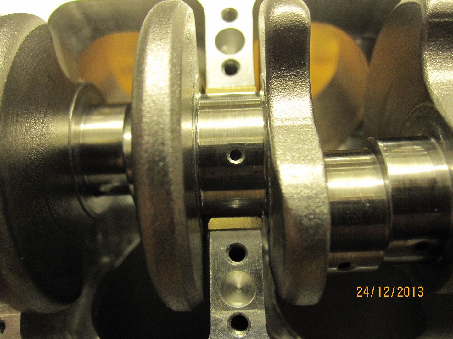
Thanks for the info, I have never seen split bearings made like that....
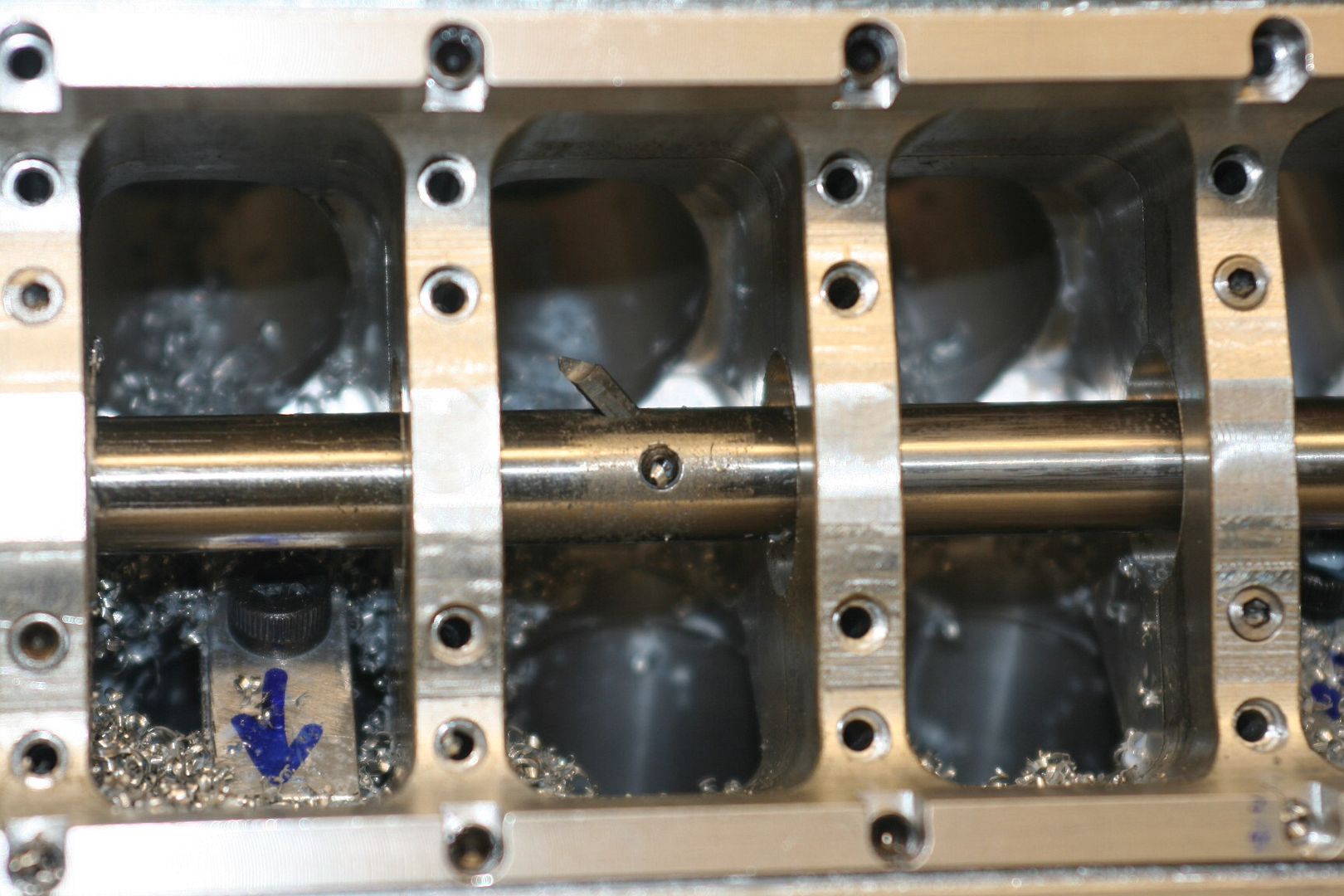
As far as pinning them goes, why not try something simple like a tang? It just keeps it from rotating while assembling... and if it does spin the bearing, it wont TOTALLY destroy the rod.

Heres a pic with the arrow pointing out the tang on a ford V8

mdmp_1003_26_+427w_raptor_engine+rod_bearings.jpg
 
Yes, 4 jaw chuck method would work just as good.

I started the block recently.
I'm going to use the dividing head to machine 90% of the block. It worked great on the V8, so no need to change technique.
The block of ally looked a bit big on it at first, but no problems with the overhang, deflection, chattering, etc.

First job was to machine the mounting features....
image_zps3a5dccd0.jpg


Then I wanted to true the dividing head up to the X and Z axes of the mill. I machined trial cuts on the block and measured for any taper, then trued the head up so the cuts would be parallel.

image_zpsb7db4bd4.jpg


Then I needed a datum on the front of the block, to measure from. I used a long series cutter and rotated the block, to produce a small dia. on the front. I know that this is concentric with the dividing head axis, and therefore true to the machine.

image_zpsf30bd69b.jpg


I borrowed a 20mm ripper cutter from work. I could take an 8mm deep cut with this. I reckon I could have gone to 10-12mm before the belts started to complain, but 8mm was more than enough to keep cool with a drip bottle.
Need to get me some ripper cutters!

Then I cut out the crankcase, and bored the block for the liners. I've left 20 thou' on all flat surfaces for now.

image_zpsff0ba972.jpg


image_zps147be56d.jpg

image_zps9ced2368.jpg
 
I see that you haven't used a centre on the other end, you mentioned that there was no chatter, I'm surprised at how rigid it is. Keep up the great work.

Paul.
 
Paul, I'm as surprised as anyone that the dividing head is so rigid, although it is a hefty beast.

Some more progress........continuing my theme of trying things I've not seen on models before, I made a bottom cradle, rather than individual main bearing caps.

image_zps8e4a3bf0.jpg


image_zpsda928ad3.jpg


Machining the bearing locations for the crank ends

image_zps4962085d.jpg


Then I made a boring bar and set the block up on the Rivett lathe. The bar runs in the ball bearings at the crank ends. The drive on the left is a hex Allen key driving a cap screw in the end of the boring bar.

image_zps1aaa4839.jpg


I realised after starting that there's no way to measure the bores without dismantling the whole set up.
Not a problem for the block bores, but as the crank is finish ground I'm going to have a problem matching the actual bearings to it.
image_zps2de8b751.jpg


image_zps26061e8a.jpg
 
NICE! Are you going to put an actual load through this motor and have it run something? awesome go kart, or massive RC car perhaps?
 
Well, my plans change all the time, but at the moment the plan is to get it running, with some form of forced induction, and then make a mini dyno and do a bit of proper testing on it under load.
After that I'm not sure. Ideal thing would be to get offered a massive amount of money for it, retire early, and get some decent cnc equipment, and see what I can make with that.
In reality I'll probably stick it on the shelf and do something else.
 
Had a good Xmas in the shed. I did the cast iron liners first. I ordered some cast iron to do a test. This was obviously poured in a mould. It was a bit rough to machine but gave a reasonable finish in the bore. Then I noticed a bit of porosity in the bore, so this was scrap. I tried some more from a different place, which was extruded cast. This machined beautifully and the finish was amazing.
Also the Rivett lathe was a godsend. I could get the size right on the first liner and then just run the others off at the same setting, and they were all bang on. Maybe this seems normal for some of you, but I've never been able to do this with my old lathe.
Some pics then...

image_zps592ff787.jpg


image_zpscc357e91.jpg


image_zps8076dbe9.jpg


image_zpsb25ecfa7.jpg


image_zps3a8c0a45.jpg
 
Keith - This is incredibly impressive work. I really enjoy watching your progress with this engine. A question about the cast iron Where did you buy the cast iron for your liners? It looks like you have extruded cast tubes, which should be great for this job and a lot less wasteful than machining from solid.
 
Hi Bill, the cast iron was from Reeves in the UK. It was just plain extruded bar, not tube. I had some more extruded cast which I think was from Chronos tools, which I've just used to make the piston rings. That was good stuff too.
The rubbish cast iron was from another place.
 
Keith, how did you end up holding your main bearings in place?
Art
 
Art, the half bearing on the sump cradle side has a small pin soldered in, similar to the con rod bearings. I didn't do the block side as the oil way will be in this position.
With the bearings being quite thick and stiff they hold themselves in place quite well anyway, so next time I probably wouldn't bother with a pin at all.
Keith
 
Keith are you still alive I hope nothing is wrong in your life really enjoyed your previous build and have followed this one to !!!
 
Keith are you still alive I hope nothing is wrong in your life really enjoyed your previous build and have followed this one to !!!

Yes, still here. The build is continuing on another forum. I wasn't sure of the rules regarding mentioning other similar forums, so didn't.
The previous post should link to the V10 build.
Cheers, Keith.
 
Thought I would post a quick update, for those that haven't seen the progress.

I'm on the final straight now, just some tidying up with bolts, etc. and some work on the cam covers around the spark plugs, and then it's ready to run.
I have had it running on a small carb but it's now got the fuel injector fitted.
The Megasquirt is just about programmed and theoretically should run it all ok.

image_zpsmzqgphxq.jpeg


image_zps8udb3fme.jpeg


image_zpsiweli88x.jpeg


image_zpsyn31zbtt.jpeg


image_zpswc01llxu.jpeg


image_zpsl63epi5k.jpeg


image_zpslspp7cnr.jpeg


image_zpscpfrzs3z.jpeg
 
Hi keith, very impressive engines, well done:eek:. I am just wondering if you have the info on the cam grinding process you used for these 2 engines? any info would be a help
Cheers
Dean
 
hello all, for those who haven't seen it, here is the engine running.
Still needs some work on the spark plugs, and a bit of tidying up.

https://youtu.be/rz0Uteqfpao
 

Latest posts

Back
Top