Dial Test Indicator - handy aid I made

Home Model Engine Machinist Forum

Help Support Home Model Engine Machinist Forum:

This site may earn a commission from merchant affiliate links, including eBay, Amazon, and others.

David Morrow

Well-Known Member
Joined
Sep 8, 2008
Messages
227
Reaction score
60
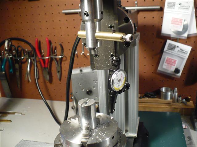
I haven't used my Starrett dial test indicator too much so haven't had much problem solving to do with it. But, the one thing that I couldn't figure out was how to center a round piece of material on my mill. It seems that everything that I read showed how to do this by indicating off the inside - assuming that everything being indicated had a center hole already drilled. I think what I needed was a DTI with some more attachments or a tip that was elbow shaped. I didn't have either. It seemed that all I needed was to get the DTI out and away from the mill spindle.

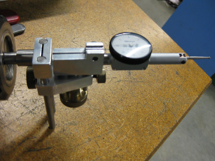
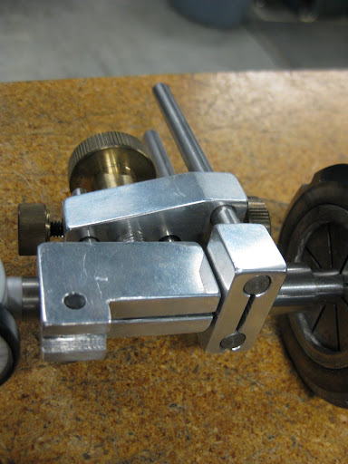
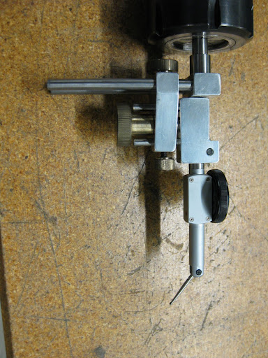
So, necessity being the mother of invention, I made up a simple device using piece of .750" aluminum turned to mount in the end mill holder. That was cross drilled for a piece of .375" brass. The brass was in turn cross drilled to hold the DTI. Both pieces are tapped 10-32 and SHCS's are used to hold it all together and make the larger adjustments for the DTI's location.

Undoubtedly one of these has already been built long ago or is for sale somewhere by someone, but for me, at least, it's original and it solved a pressing problem.

DTI-Aid.JPG
 
I like it. Will be adding it to my to do list
Regards
Ernie J
 
Very nice solution, David.

I think you will find it useful for more than just centering work. Any time you need to dial in an edge away from the spindle you now have a convenient indicator holder. You will also find it handy for an accurate tram of the mill head. The farther away from the spindle you can get, the more accurate your tram will be.

Cheers,
Kevin
 
Nice solution to an age old problem. That's the nice thing abouthaving a home machine shop, being able to make what you need. Looks like it will work just as well as the expensive ones you can buy. I think I'll add it to my to do list also.

Have a great day,

Kevino
 
Nice work David. :bow: Now chuck the ally end in a tailstock drill chuck and you can use it on the lathe when you use your 4 jaw chuck.

Cheers,
Phil
 
In one of his "Bedside Readers", Lautard describes the Osborne maneuver for accurately finding the center of cylindrical stock on the milling machine with nothing more than an edge finder.

Use the y-axis control to set the edgefinder by eye to the midpoint of the part. Now, using the x-axis control, touch off with the edgefinder. Move towards the part center by half the part diameter plus half the edgefinder diameter. (You'll now be near the center of the part.) Touch off in the y direction and again move half+half to the center (you'll be nearer to the center of the part.)

Repeat this entire procedure once more and you'll be pretty darn close. Further iterations further reduce the error but three is more than enough.

The output below, from my OSBORNE program, shows how rapidly the error diminishes. Starting with an initial offset error of 0.1" (well within the accuracy of the Mark 1 eyeball), we're down to an error of only 0.005" after the second iteration. One more iteration reduces the error to the proverbial RCH.

OSBORNE MANEUVER

Workpiece diameter [2] ?
Initial offset [0.1] ?

iteration: del1,del2,error= 1: 0.10000000, 0.00501256, 0.10012555
iteration: del1,del2,error= 2: 0.00501256, 0.00001256, 0.00501258
iteration: del1,del2,error= 3: 0.00001256, 0.00000000, 0.00001256
iteration: del1,del2,error= 4: 0.00000000, 0.00000000, 0.00000000
iteration: del1,del2,error= 5: 0.00000000, 0.00000000, 0.00000000
iteration: del1,del2,error= 6: 0.00000000, 0.00000000, 0.00000000
 
As a bit of a coincidence, Guy Lautard lives just across English Bay from me in West Vancouver - I'm in Vancouver (Kits area).
 

nice bit of tooling you made there.

Here is one I made from Marv's link. For the dovetail, I roughed it out with an endmill then opened it up with a single point form tool I ground and expanded per pass using a boring head until I was happy with the fit.

zero%20it%20003.jpg


zero%20it%20006.jpg


zero%20it%20002.jpg


I also have a couple extra sets of rods for large bores and traming heads.
 
Back
Top