Building Rudy's Steam Tractor

Home Model Engine Machinist Forum

Help Support Home Model Engine Machinist Forum:

This site may earn a commission from merchant affiliate links, including eBay, Amazon, and others.
very nice . im in school everyday here. always want to see how these things were done. great work
 
Down here in Texas the terminology that I learned for the cleats on caterpillars was grouser. It is the type of cleat or lug used as a average trade off for traction on soil as well as hard surfaces The flat lug surface does not tear up the road surface as much as the deeper cleat or lug , Whatever the name --you did an excellent job replicating them .
Also the 67 1/2 degree angle allows the wheel to dig in and use side thrust of the wheel to maximize the available traction . That is why the current tire manufactures still use this concept on Ag cleat tires richard
 
This is on my build list. My moms father has a real 65 hp, I get to play with from time to time, as you can see by my avitar. My wife gave me the book for my birthday, and I have most of the material in the shop. Now if I could just find the time to get in the shop more often. Will probably have to wait until fall now, too much going on this summer. Thanks for taking the time to document your build, I am sure I will learn from it.

Dale

 
Installing the Grouters

The grouters are riveted on with 1/16” round head rivets. I made a rivet back-up tool using a piece of mild steel and a 1/8” ball end mill. Mill only as deep as the thickness of the rivet head.

P1030527.jpg


Insert a rivet into one of the predrilled holes in the rim and roughly position the grouter. Then flatten the rivet with a ball peen hammer. Note: The wheels are right and left handed (inside edge of the grouter leads the rotation), so be careful to change the direction of the grouters on the second wheel.

P1030473.jpg


Lay the wheel on a flat surface and final position the grouter with a gauge.

P1030476.jpg


Clamp the grouter in position and line drill the second hole.

P1030493.jpg


Install a rivet & set it (Note: At this point, I’d started using a flat bottom rivet set because I found that the ball peen hammerer tended to leave small dings in the brass).

P1030495.jpg


Protruding bits of the grouters were removed by fastening a piece of 320 grit paper to a flat surface and rubbing the wheel over it until the grouters were flush. The home made rivet tool preserved the round heads of the rivets pretty well.

P1030496.jpg


The entire outside of the wheels was then buffed with maroon scotchbrite to complete them.

P1030500.jpg


Regards,

Dennis


..whaoooooooo nice work...
best regards
paolo
 
I too have been working on one of these fine models recently and went one step further in the development of the rear wheels in that I threaded the hubs and spokes and then used jam nuts to secure the spokes to the hub. Solder was used on the rim end. The rims that I made were from a piece of cast iron water pipe that was being thrown out.

22a.JPG


20.JPG
 
Well, at the start of this thread I said that if I got through the rear wheels I’d probably continue with the project. So here I am feeling pretty good and ready to continue. Disaster must lie just ahead

Thanks for the comments & responses. It’s always nice to know someone is watching. I particularly appreciate the input from current and past builders of this model and hope they’ll continue. I’m a beginning builder with limited equipment, so most of my approaches and posts are pretty basic. However I hope that won’t stop experienced builders from chiming in when they have a better, other, or more advanced way of building something. Also, if you know of upcoming potential pitfalls (like “ghart3” and “DougLanum”s input about reducing the gear ratio) please let us know.

Forgive me if I occasionally show the obvious. It’s hard to know what might be of interest. As a beginner I tend to want to see more rather than less. My hope is to at least show a picture of each part and to note any places where I deviate from the Village Press plans.

Regarding the plans…some time ago I read a Rudy Kouhoupt interview where he mentioned that the Popular Mechanics plans had errors in the steam chest/valve dimensions but that they had been subsequently corrected. Does anyone know anything about this?? I’m wondering when they were corrected and if my Village Press plans have the correction.

Thanks again for reading. More build shortly.

Regards,

Dennis

 
Dennis, I did not find any errors in that area and I just finished those pieces about a month or so ago. I fabricated the cylinder/valve face in two pieces and silver soldered them together. The hardest operation for me was milling the ports. I am interested seeing the mod that a builder presented here earlier pertaining to the cross head trunk guide. It seems to be a bit sturdier as well as appears more to scale than two plain square rods.
 
I will try to take some photos this weekend of the different cross head design and post them.
I'll also check to see if I have any sketches or dimensions stashed away.

There were questions about the tractor operation and I'll put some comments together on that too.

One thing a friend and I both did for our tractors was to make a small fan to fit on the smoke stack while building up steam pressure. It speeds the process up but also keeps the flames from the alcohol burner going in the right direction.


Doug.
 
Doug, that would be a great help if you could muster up some photos and dims. regarding the crosshead, and thanks for your help.

Jim
 
bearcar1....Thanks for the info on the dimensions. That's one item I can quit worrying about.

DougLanum...Looking forward to more detail on your crosshead. It sure looks good. Thanks.

Dennis
 
Front Wheels

The front wheels are a little simpler than the rear in that they only have 16 spokes per wheel and no grouters. I used a 3” copper sweat fitting for the rims. The fitting OD is 3.283” and the ID is 3.133”. Rudy’s plans call for 3.250” and 3.125”. The front wheels were built using the same fixtures and methods as the rear wheels so I’ll only show the differences.

The hubs were drilled on the same fixture as the rear wheels except the 24 spoke pattern was replaced with a 16 spoke one. The hubs on the front wheels don’t have a setscrew, so to hold them for drilling, I mounted them in the fixture and put a drop of superglue in the joint. Worked great. A sharp rap on the end of the shaft broke the joint for removal (superglue doesn’t like shock loads). Heat would probably have worked too.

P1030506.jpg


The front wheels are wrapped with a 1/4" wide tire fastened with five rivets. I didn’t pre-drill holes in either the rim or the tire. The rims were preformed from a strip of 1/4” 0.032” brass. Use an extra long strip to get a smooth beginning and end. Note: Any brand of Garbonzo beans will work ;-).

P1030518.jpg


Clamp one end of the tire in position, center punch, drill and install the rivets one position at a time 90 degrees apart. I didn’t cut the tire to final length until I was ready to install the last rivet.

P1030521_edited-1.jpg


I found that after the first rivet, it helped to clamp the tire down on both sides of the rivet when drilling and riveting. Here are the finished front wheels.

P1030669.jpg


Dennis


Here is some more information about Rudy's tractor that I built.
Mine was completed about 30 years ago, and has run lots and lots.
Some of the changes and suggestions were based off of information from a friend who had built one of these too.

The gear ratio was changed to slow down the speed of the tractor. This seems to be a more realistic speed and allows more power. It will easily pull itself though grass or along a gravel road at the local engine / tractor show. It always draws attention.

I found notes on the gears i used:

the crankshaft pinion is 20 teeth, 0.417 " Pitch dia. 1 required.
the idler gear is 72 teeth, 1.5" PD 1 required
the counter shaft gear is 100 teeth, 2.080" dia. 1 req.
the counter shaft pinions are 16 teeth, 0.335" PD. 2 required.
the bull gears are 120 teeth, 2.5" PD. 2 required.

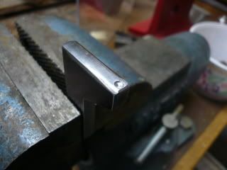
The crosshead design was changed to match a more prototypical design.
It is close to what Case used and is a more sturdy design.
It is made of brass, and photos will follow soon.

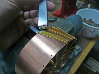
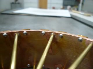
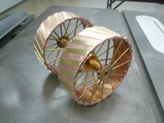
We also made small fans to put on top of the stack while building pressire.
We found that the alcohol burners had flame going everywhere, so the fan keeps the fire going the right direction. It also allows the steam pressure to build much quicker.
once pressure is built8 up, and the engine is running, the engine exhaust provides sufficient draft.
This fan is made with a simple bent blade impeller and a small 1.5 volt. motor.

Since there is no water level gauge glass on the boiler, you can't tell how much water is there.
To Begin, I unhook the pressure gauge compression fitting and take a plastic squirt bottle and a short length of tubing to fill the boiler through the 2nd fitting and valve. I stop when the water comes out of the pressure gauge pipe fitting.
You will need to learn how much alcohol needs to be put in the burner to time it running out about the same time as the water. When pressure drops, after about 20 minutes, the boiler may be dry. Be sure to check to see if the fire is out too. You may need to pick the tractor up and flow the fire out from under the fire box.

I also put a "T" pipe fitting under the safety valve and made a small whistle to connect to that.
More fun.'

Photos to follow

Doug


Thank you very much Doug for that gearing information, I have made written corrections in my notes and am going to now look up the PNs in the Boston Gear catalog. I cannot wit to see the pictures and specs on your crosshead modification.
Best regards
Jim B.
 
That should make a very robust mod to this engine, it makes better sense this wy and is more scale-like in appearance. Thanks again Doug.

Jim B.
 
Jim,
You are welcome.
I have more photos to send, but I've run into a snag sending them.

Doug
 
for those detailed oriented and history buffs that are building rudys engine here is an interesting reference a Case steam engine parts catalog many photos and sketches some with a few dimensions.
Case Parts Book.pdf
tin
 

Latest posts

Back
Top