Please may I tap into the vast knowledge base of the HMEM members?
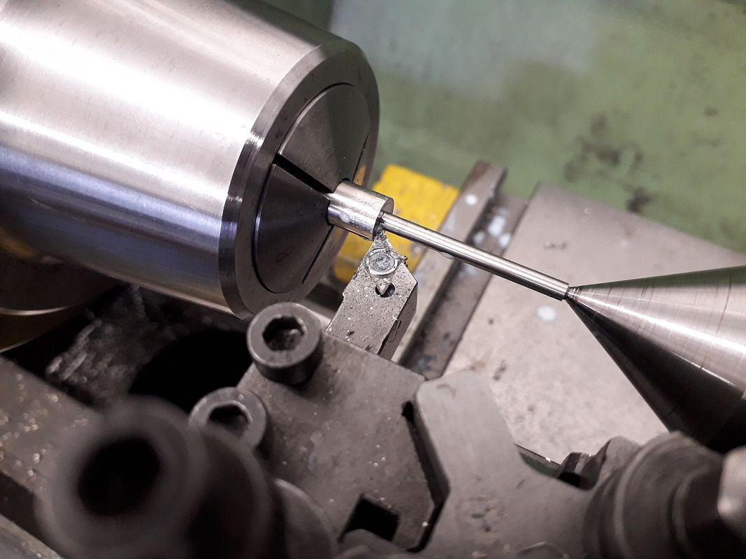
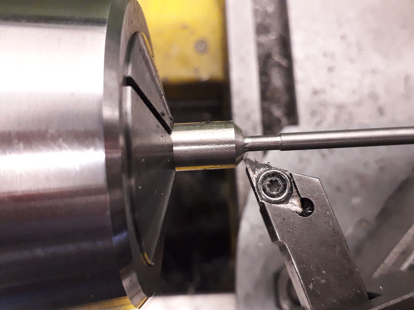
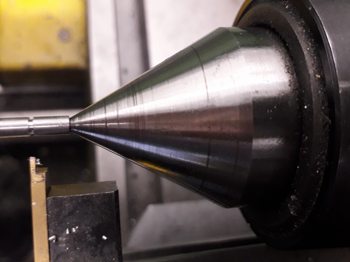
I need to machine the valves of the Kiwi and I can’t formulate a procedure which will give me a 1.5inch long x 0.125dia valve stem which is a good sliding fit into a reamed hole. I’m using silver steel (drill steel).
I could machine with a tail stock centre but there is little material for the centre drill and there would be bowing in the centre of the unsupported stem. I could machine to the diameter of 1/8 (from 3/8) in small steps but I would still need to take a final cut. I could fabricate but I have never heard of anyone doing that and I can’t believe it would work. I could rig up some sort of travelling steady but this would need to be adjusted for every cut – would work I guess.
So can you Guys suggest the preferred machining process to use?
Many thanks in advance
Mike