Help with ignition for inline Ford 6 Cylinder model engine

Home Model Engine Machinist Forum

Help Support Home Model Engine Machinist Forum:

This site may earn a commission from merchant affiliate links, including eBay, Amazon, and others.
Joined
Mar 4, 2023
Messages
13
Reaction score
1
Location
United States
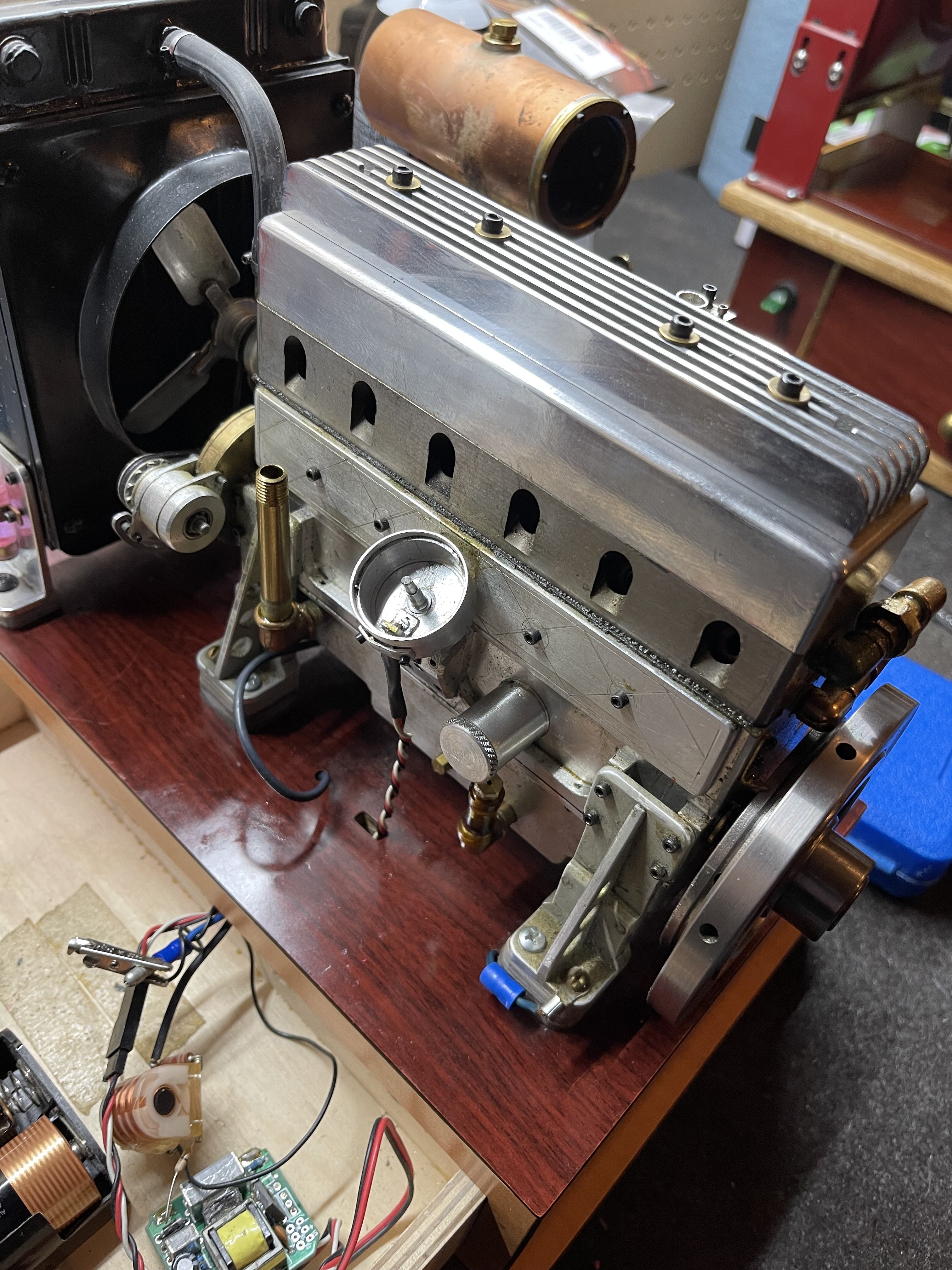
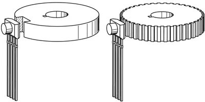
Hello everyone. I recently purchased a scale model Ford 300 6 cylinder from the estate of a very prolific engine builder. I have a video of it running before the builder passed away. My challenge is the ignition is no longer working and I am trying to find what appears to be a Hall sensor ignition. Rather than having a Hall sensor mounted stationary with a magnet triggering the ignition, it has a fixed magnet inside the tiny distributor that is triggered by a reluctor wheel. I have attached pictures in hope that someone will be able to assist me in my search to find a replacement ignition that will work in this configuration.


Attachments

  • Electonic ignition for 6 cylinder ford engine model.JPG
    Electonic ignition for 6 cylinder ford engine model.JPG
    1.7 MB · Views: 14
  • Distributor with magnet hall sensor 6 cylinder ford engine model.JPG
    Distributor with magnet hall sensor 6 cylinder ford engine model.JPG
    1.9 MB · Views: 10
  • Ignition in Ford 6 cyl engine reluctor and cap 2 model.JPG
    Ignition in Ford 6 cyl engine reluctor and cap 2 model.JPG
    2.1 MB · Views: 3
  • Ignition parts -reluctor and cap n Ford 6 cyl engine model.JPG
    Ignition parts -reluctor and cap n Ford 6 cyl engine model.JPG
    2.6 MB · Views: 7
It is possible to have a stationary hall effect operate from a slotted metal disc if one mounts a magnet of correct polarity to the back side of the hall effect.

The hall effect unit is most likely an open collector device so fairly simple to test with a multimeter set to read voltage.

Video, look at details of A3144 switch.......

Thing is, including the switch in the same enclosure as the HV for the spark plugs is a bad idea.
Unless of course , one has it extremely well isolated from the high voltage.
Never seen one yet that doesn't get zapped at some time due to the above method.

As an added note, I wouldn't put too much faith in getting that pictured so-called CDI to run successfully, especially with 6 cylinder demand.
 

Attachments

  • Alegro Hall effect.jpg
    Alegro Hall effect.jpg
    13 KB · Views: 3
Did you happen to watch the video I shared. The engine did in fact run very reliably of over 12 years. I do appreciate your comments though and will attempt to test it. I hope I don't have to send it to China to get it figured out.
 
That ignition system is fine for your engine. I have been running my v8 on that same equipment for many years. More than likely your hall sensor has failed. Try a new hall sensor and make sure you have a good ground connection or the system will find another path which usually ends up being the ground for the hall sensor and poof.

That board is good for 15,000 sparks per minute. You should achieve 6000rpm with 6 cylinders. Roy had modified boards that could double that number. In the v8 they are good to 7200rpm.
 
Last edited:
I was very good friends with the builder and he built that engine from my drawings. I made the camshaft for it because it required helical gears in the middle of the cam. Another gentleman on this forum ran a build article on the construction of his engine. (Terry Mayhugh) The ignition for this engine is my design and has worked very reliably. I would suggest that the Hall sensor has failed. If you go to my YouTube channel (gbritnell) you will see a video of this engine right after I made the cam and got it running. It's listed as Sunias engine.
 
Good morning Mr. Britnell,

I appreciate your writing to me. I spoke with Sunia's son, Michael this morning and then saw your post here. So glad to hear from you. I would appreciate being about talk to you about the engine and especially the ignition system and parts. Michael was kind enough to share your email with me.

Best regards
Shelby
 
Steve and George are most likely correct with the hall being fried. That is one of my old original CDI's. 6 volts MAX and they ran the most efficient on 5 volts.

In the photo of the CDI it looks like the Spark Coil ground has come loose. Attached is what it should look like. The loop on the coil is for the ground wire to the engine. The Spark Coil was glued to the gray capacitor and board. You need to reattach the coil ground pin to the circuit board.
 

Attachments

  • GEDC0008.JPG
    GEDC0008.JPG
    306.4 KB · Views: 5
Steve and George are most likely correct with the hall being fried. That is one of my old original CDI's. 6 volts MAX and they ran the most efficient on 5 volts.

In the photo of the CDI it looks like the Spark Coil ground has come loose. Attached is what it should look like. The loop on the coil is for the ground wire to the engine. The Spark Coil was glued to the gray capacitor and board. You need to reattach the coil ground pin to the circuit board.
 
I doubt there is anything wrong with the unit you have Shelby but I do have replacement units for the one you have. Send me an email, right now I'm behind and trying to get caught up. I'll can also check out and repair the system you have now it you want to send it to me.
[email protected]
 

Latest posts

Back
Top