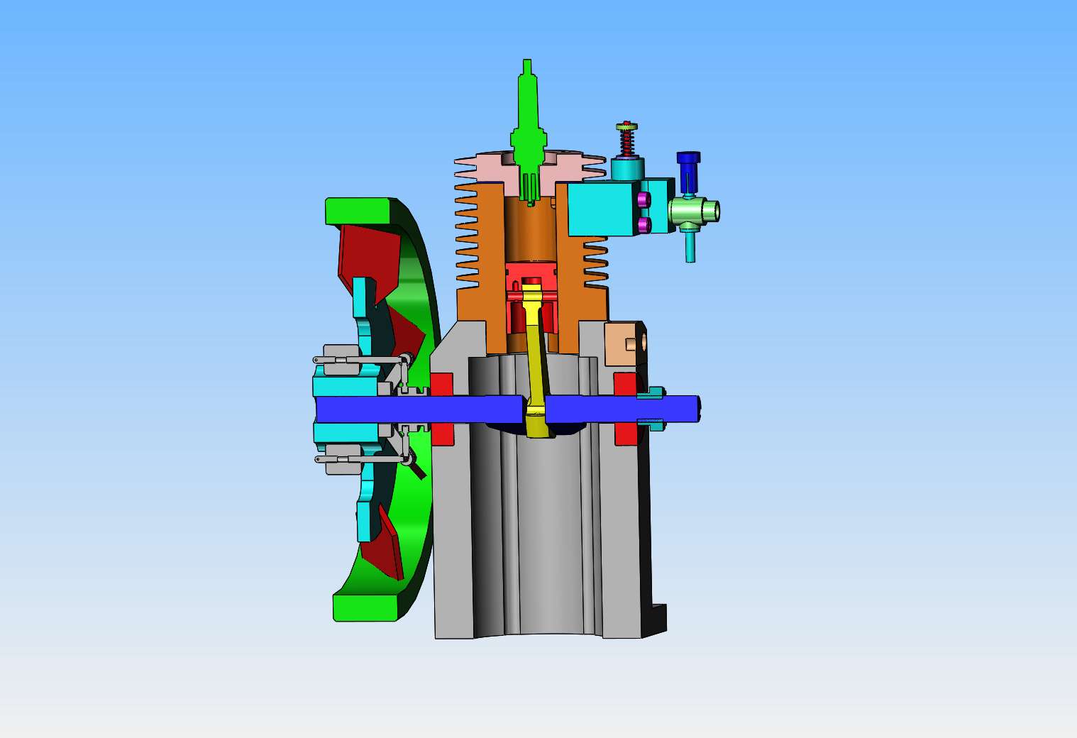
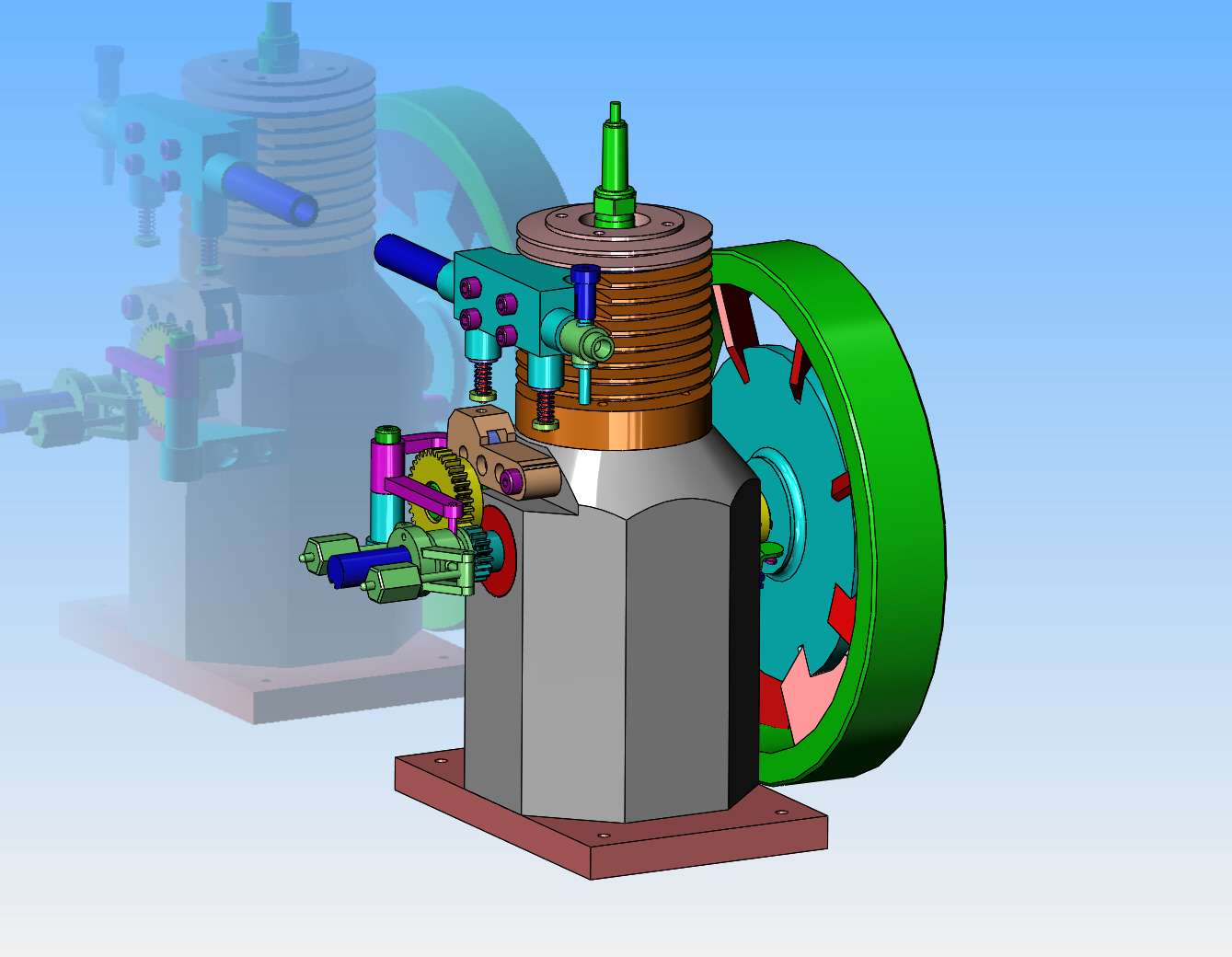
Hi Brian, The deep/tall crankcase reminds me of how the early engines had oil reservoirs beneath the crank, then a dip-rod projecting below the big-end of the con-rod, with a small lubrication hole in the big-end so the splash lubrication was driven up the dip-rod into the bearing lubrication hole.
I remember some rods (1960s repair shop) where I had to file a slight concave groove in the dip-rod to "encourage" more oil to run up the rod (that had been convex) to the lube hole. Supposedly to increase the oil supply to the bearing. Did it work? - WHO knows? I can imagine that the "splash" of oil inside the crankcase ensured everything was well covered in oil...
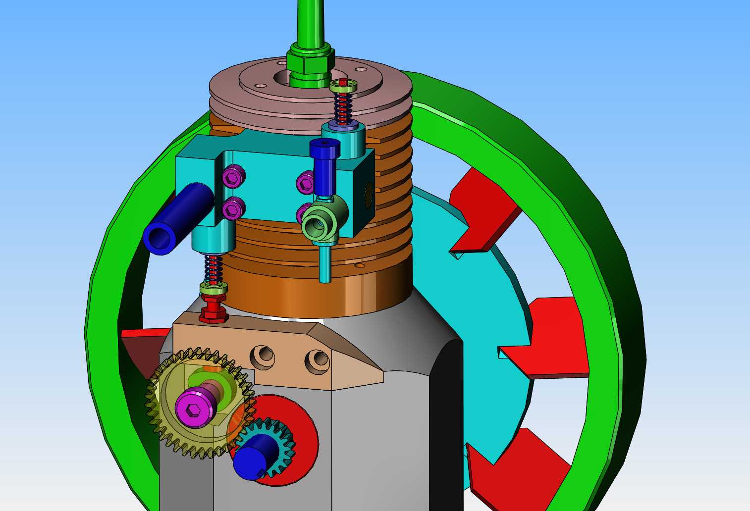
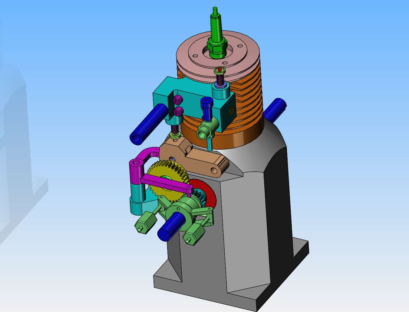
That aside, I think you need to decide if you want direct (straight-line action) from cams to valves, or a rocker cam follower (curved motion) to the push-rod, that gives you lots of scope as to location and hit 'n miss latch. Rockers are great for altering the mechanical advantage of the cam-to-push-rod motion, and to alter the line-of-action of cam contact to push-rod by being anything but straight. (Bent cranks go around corners!). The disadvantage is usually the moving mass (inertia) - But not in your case, as it is not designed as a "high speed" engine.
K2