Newest hit and miss engine from China--Hit and miss mechanism

Home Model Engine Machinist Forum

Help Support Home Model Engine Machinist Forum:

This site may earn a commission from merchant affiliate links, including eBay, Amazon, and others.

Brian Rupnow

Design Engineer
Project of the Month Winner
Joined
May 23, 2008
Messages
14,886
Reaction score
8,213
Location
Barrie, Ontario, Canada
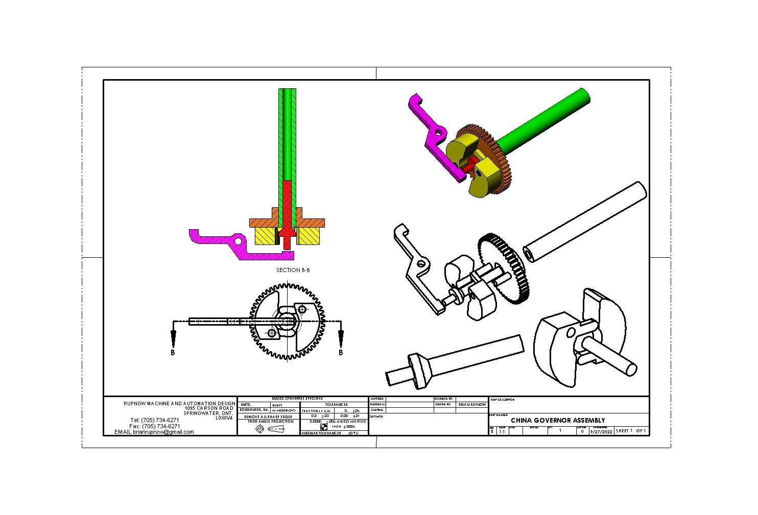
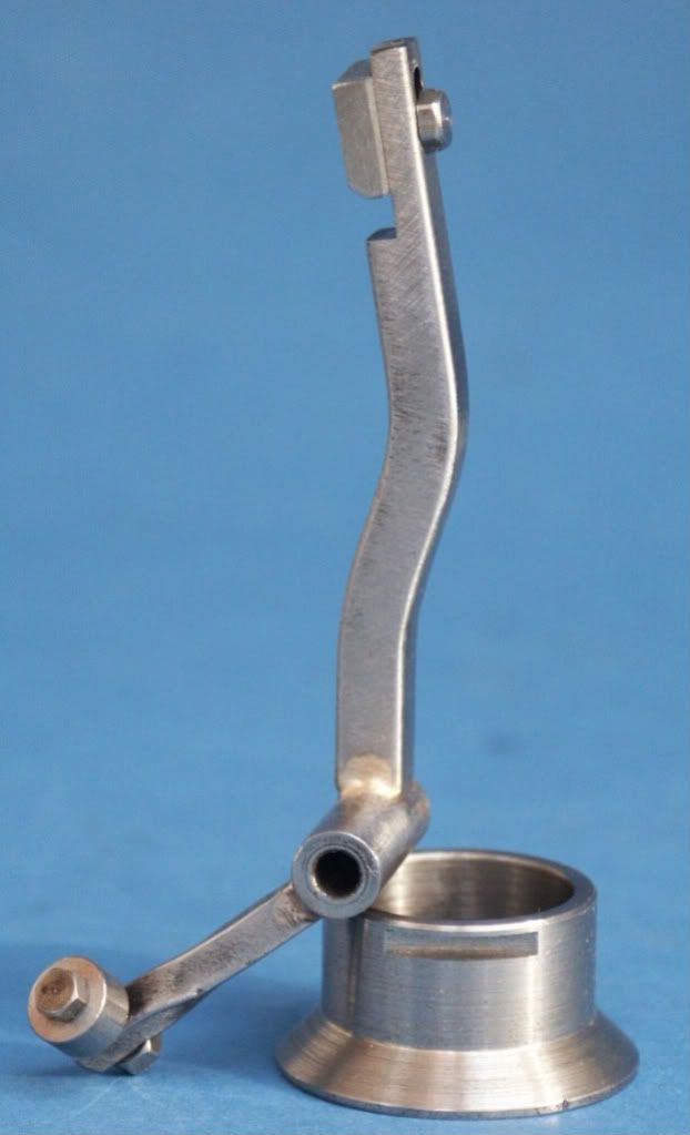
I watched a video of the newest (2022 version) of the hit and miss model engine from China yesterday. Instead of the governor weights being attached to the flywheel and a sliding sleeve on the crankshaft, it appeared to have the governor weights attached to the camshaft gear. I couldn't clearly see what was going on there, but it was different than the first China hit and miss engine which appears to be a direct rip off of the Kerzel engine. Does anybody have any clearer shots on this new governor arrangement?----Brian
 
I don't have clearer shots, but Paul Breisch's 1/2-scale Olds Type R has the governor weight mounted on the cam gear, as does the full-scale engine, of course. It works fine. Back in the day, it seems like the mechanism would have been cheaper to built and assemble as a bolt-on package compared to weights on the flywheel driving a sliding collar on the crankshaft.

Governor Partial 1.png
Governor Partial 2.png
 

Attachments

  • IMG_5646 2.MOV
    18.7 MB
Thank you rklopp. Of all the engines that I have designed and built, or built from other peoples plans, the hit and miss engine remains my favorite. I have built the Kerzel, the Odds and Ends, and a hit and miss side shaft engine, and a famous oscillating hit and miss gas engine by Philip Duclos. The type of hit and miss mechanism you have shown me is much, much simpler than the mechanism on the Kerzel. The Chinese 2022 version seems to have two counterweights on it, and I think that they pivot at 90 degrees to the Olds engine you show.
 
Last edited:
I sent the fellow who appears in the video an email today, asking him about the governor. If he gets back to me, I'll let you know. It seems that the manufacturer or at least the seller is Banggood.
 
Last edited:
From what I am able to see, this is what I think the governor looks like. This doesn't seem right to me but it may be. The red coned part floats in a hole centered in the end of the camshaft. The weights are shown in the zero or slow speed configuration, but as soon as the engine speeds up centrifugal force causes the counterweights to pivot and try to fly away from the centerline of the shaft. The two narrow fingers on the counterweights bear against the cone, forcing it to move outward and contact the lock-out arm, causing it to pivot and "lock out" the exhaust valve. In theory it would work but ---
XHwHlv.jpg
 
I found yet another video of this engine running with a good side view of the governor side. it seems to confirm what my drawing shows.---Brian
 
Brian-

I think you are correct about the cone on the shaft.

I guess there could also be a flange offset from the cone, to capture the shaft, and limit its outward travel.

So the tab would ride between the cone and the possible flange.

I see a lot of different ways to do the same thing in the engine world, and I know for a fact that much of it was to avoid patent conflicts.

Pat J
.
 
I don't think the Chinese worry too much about breaking patent laws. I think that there is a compression spring on the far end of the lock-out rod which means that the governor end of the lockout rod always bears against the end of the tapered sliding part to keep it from coming too far out.
 
The only way to test my theory is to build such a mechanism. The gear shown in my drawing doesn't have to have teeth to test this mechanism. This may give me something to do while I wait for my new carburetors from Ebay show up here.
 
I don't think the Chinese worry too much about breaking patent laws.
Yes, but I was referring to variations I have seen on old engines, governors, etc.

To be completely fair, people in the US and all over the world have been known to infringe on existing patents, and this often leads to long and extremely expensive lawsuits, which I have read about, most recently between high tech titans.
We can't really say it is just one country doing this sort of thing, and this is nothing new either.

.
 
Brian the cone is likely to have a spring along it's axis somewhere as the cone would need t be able to return to the unlatched position

The IHC that I build used a cone but that was operated more like the spool on a crankshaft so as the cone moved so did the latch that ran against it

PICT0332.jpg
 
Last edited:
I spent yesterday and this morning building a governor as per the drawing I posted. Instead of a 90 degree contained angle on the cone, I went with a 120 degree contained angle . It works surprisingly well, and as Jason said, there is nothing on the governor to bring the weights back to center when the engine slows down. That is why I made reference to a spring on the lockout lever, forcing it to pivot and bear against the end of the coned part---This is what moves the governor back into the slow running condition. With 120 degrees of contained angle on the coned part, I get 0.075" of linear movement on the center spigot that the cone is attached to. I could try one with a 90 degree contained angle, which would give me more linear travel, but the governor might not be as responsive then. I am going to do up a video of the governor working after I finish this post.---Brian
 
I have read about steam engine governor design in the mid 1800's, and Charles Porter (in addition to designing the first high-speed stationary steam engine) also designed a highly accurate governor for stationary engines.
Modern analysis of Porter's governor seems to indicate it was an isochronous design, and highly accurate.

So what made it so accurate?
As I recall, he operated it at a speed higher than crankshaft speed.
And his design had flyballs that were relatively small, and also a large central weight, that was not attached to the central shaft.

So the flyballs worked off of inertia, and the central weight worked off of gravity only, and I think the result was a non-linear but highly accurate response.

I think Brian's refrence to "linear" means "straight-line motion".
I would assume the governor in question may or may not provide linear control, but from what I have seen they work well.
I guess linear/non-linear would be a discussion in and of itself.


Porter-Engine-04.jpg
 
This is rather like trying to get a video of the abominable smowman, or the Loch Ness monster. It works, but I have to try a number of different strength springs until I hit the magic number that is worthy of a video.
 
I made the "cone" part of this from 01 steel so I could flame harden it. Tomorrow, before I harden it, I will get out my kit of buffs and polishing waxes and polish it to a mirror finish. The microscopic ridges left from the lathe tuning operation make it kind of "sticky". I am very busy with an ongoing design job, so this will get done when I get time for it.
 
Success!!! Found this video tonight. Beginning at 7:15 there are great views of the governor weights, the cone and the face of the gear. I had it right.
 
And today, we have a video. Top speed of my lathe is 750 rpm, and things are a bit sticky, but this governor does work. I will try it later today on a cone with an included angle of 90 degrees to see if that is better or worse.
 
Back
Top