1" Bore x 1" Stroke Vertical i.c. Engine

Home Model Engine Machinist Forum

Help Support Home Model Engine Machinist Forum:

This site may earn a commission from merchant affiliate links, including eBay, Amazon, and others.
The gaskets are all made and installed (except for the one between the crank-case halves). The ignition timing has been set. In this picture I am setting the exhaust valve opening with a printed degree wheel and a pointer attached to the crankshaft. This valve is easy to set. I just loosen off the set screws holding the small gear to the crankshaft, rotate the flywheel until the piston is at the very top of it's stroke (as determined by a a hex wrench down the sparkplug hole resting on top of the piston), this corresponds with the zero degree mark on the degree wheel. Then turn the flywheel until the pointer is pointing at 25 degrees before bottom dead center and lock the crankshaft in position. Then I turn the large gear on the camshaft in the appropriate direction, until the cam just contacts the lifter and starts to move the rocker arm. Then I tighten the set screws in the small gear on the crankshaft in that position. Setting the intake cam position is going to be considerably more difficult, as I have no access to the cam to lock it to the cam shaft. I will have to calculate the degrees of offset between the intake and exhaust valve and remove the camshaft from the engine to set that. For the sake of the picture I have turned the flywheel and crankshaft to a position that shows the pointer.
kJ1HWs.jpg
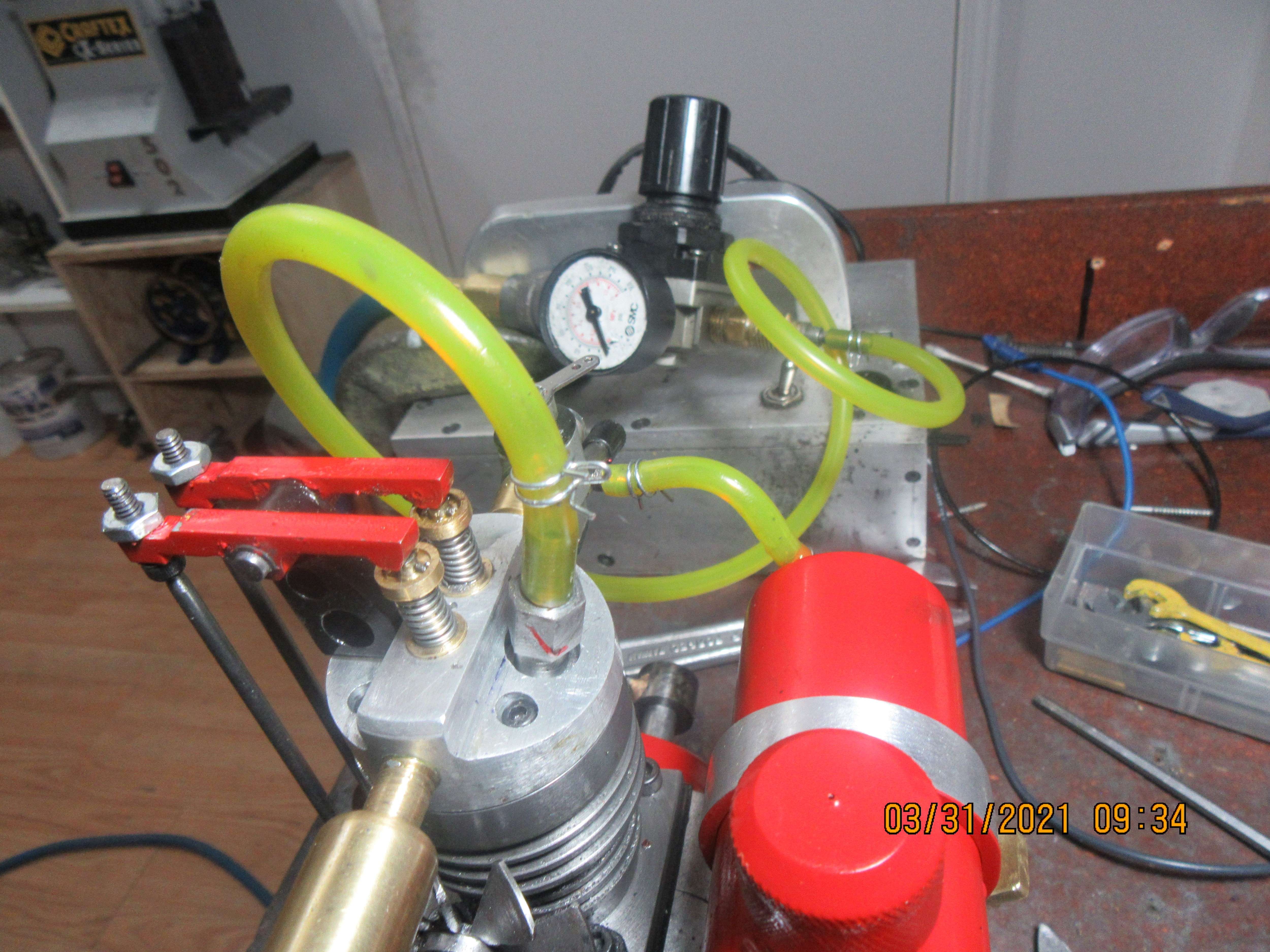
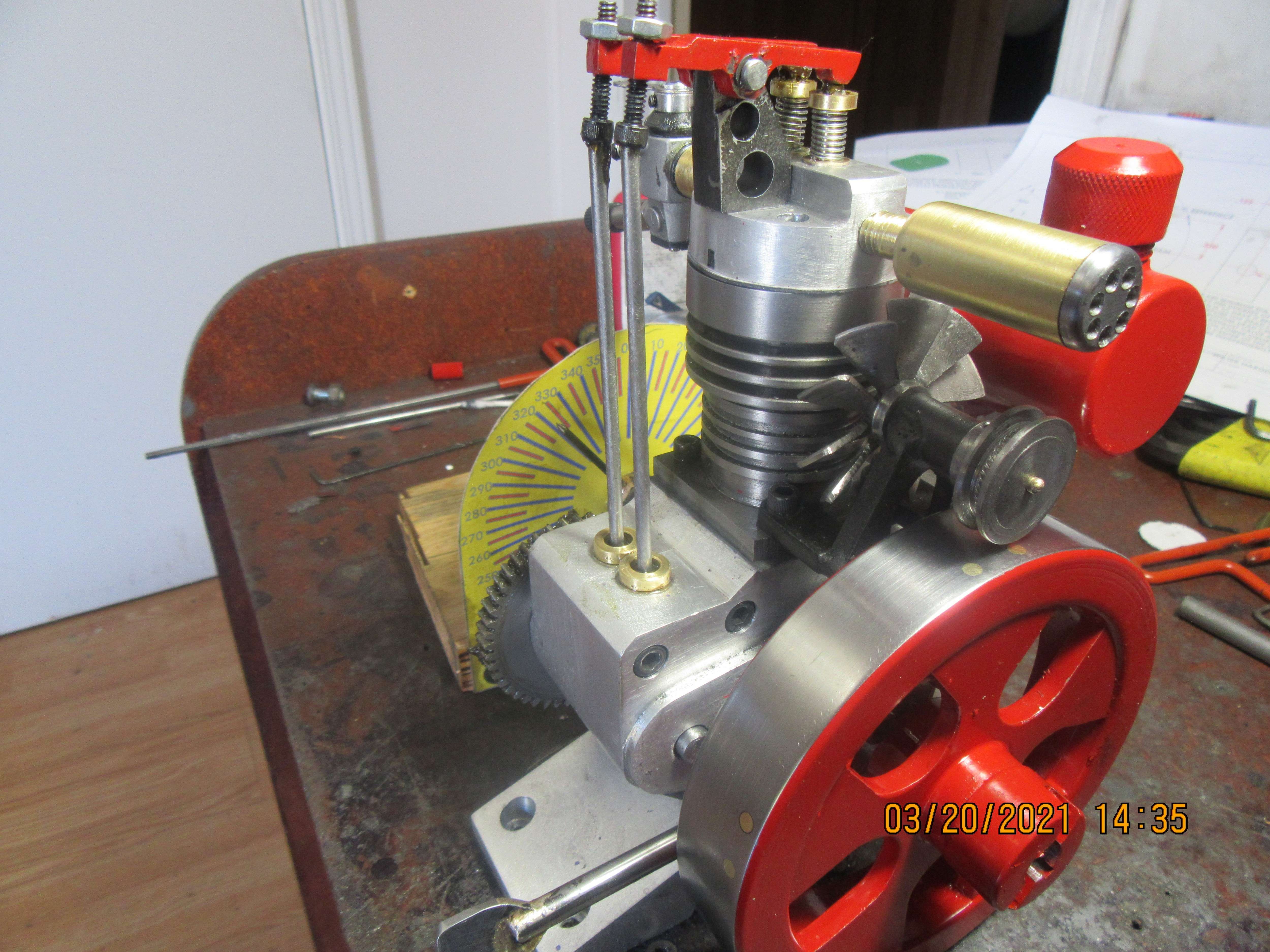
Looks like you could fit a neoprene o-ring on the fan pulley and just run it on the surface of the flywheel. Might be easier than a big belt around both.

Really like the design
 
hi Brian, not to beat a dead horse on the gear but if i ever have a scrape or bruise that i have to explaine to someone then i call it a massive bar fight and i won or i ran etc. so call it "well i was having a GREAT time doing something" lol

at any rate i see you are using a 1/4 x 32 plug over the usual cm6 you often use. i just want to watch and see your setup for that with your external ignition kit. i use an external ignition kit as well, i made an adapter that works just fine but am interested in how you and everyone else does it. assuming your going to use your portable ignition unit.
 
Brian:
While you have the pressure testing setup you can measure your "real" valve timing by using your degree wheel and listening for the valves to open and close. Just for piece of mind that it's as expected.
 
Werowance--Normally I use the 10 mm sparkplug because it is available thru PartSource as an automotive part. however, on this cylinder head design, there wasn't enough room for a 10 mm plug. Thats why I went to the 1/4"-32 plug. DSage--You can't hear these valves opening and closing. You have to do it by eye when you see the rocker arm start to move, or with a dial indicator as I showed in an earlier post.----Brian
 
Werowance--Normally I use the 10 mm sparkplug because it is available thru PartSource as an automotive part. however, on this cylinder head design, there wasn't enough room for a 10 mm plug. Thats why I went to the 1/4"-32 plug. DSage--You can't hear these valves opening and closing. You have to do it by eye when you see the rocker arm start to move, or with a dial indicator as I showed in an earlier post.----Brian

To clarify:
With the air pressure applied to the cylinder through the spark plug hole you should be able to hear the exhaust valve open / close by the air pressure release / cut off in the exhaust pipe and the intake open / close at the carb. Then you take note of those points on your degree wheel.
 
Brian; Been following this build with great interest. Just looked back at the Mar 3 post of installed fan . Is it going to stay together at 7500 RPM ? Assuming 5 in flywheel and 3/4 in fan pulley its gonna be buzzing at 1000 engine RPM. Just saying, Colin
 
Brian appreciate that (the link), my ignition unit is very similar to yours. full size ford style coil , using regular points, on off switch, ballast resister etc. i guess what i was really wanting to see is how you brought the spark from that coil over to the 1/4 32 spark plug. i made an adapter for mine which i am ok with the result but this is something that i feel i could do better at and just am curious to see how you bring the coil wire from the top of the ford style coil and adapt it down to the smaller plug. the cm6 would actually accept a normal ford coil plug wire where the 1/4 x 32 needs something smaller. so wanted to learn about your solution as many do their own little built in coil just for that engine where you often use your portable coil system. and i also think thats a good idea and do the same.
 
Last edited:
Okay Werowance---Here you go.---Find a piece of wooden dowel that is a "good" fit into the end of the coil, and long enough to stick out thru the hole in the box about 1" when it is seated in the coil. Drill a hole lengthwise thru the piece of wood, big enough to run the insulated coil wire completely thru it. The coil wire should be about 18" long between the sparkplug boot and the bare end which fits into the wood. Cut about 3/4" of insulation away from the non sparkplug end of the coil wire. Coat the last 3" or 4 " of the stripped end of the coil wire and coat it with slow setting glue and push it thru the wood until the bared end sticks out of the wood. Fold the wires back over the outside of the wood, coat them with glue and smooth them against the wood. Now, when dry, you can insert the wood thru the hole in the box into the coil.---If you require a different sparkplug boot, make up a second coil wire assembly. the 1" of wood which extends beyond the side of the box lets you grip the wood in your fingers and pull it completely out, then you can push in a different coil wire assembly.
 
A pressure test of the cylinder indicates that I have a very leaky head gasket just below the inlet from the carburetor. I'm not certain why, but I will pull the head off and take a look. I generally don't have problems with leaky head gaskets, and since this is the second time a head gasket leak has been indicated I will have to closely check the cylinder head and cylinder to make sure there is not some mechanical issue preventing the head gasket from sealing.
42V34Z.jpg
 
YES!!! Engine is up and running on it's own. Right now I need to grow about three more hands to run the starter (my 3/8" variable speed drill) and the throttle and the timing lever, but we are running. HAPPY DANCE!!! A video will follow when I get to it.
 
Here we go---first run!!! Tomorrow I will spend a bit of time taming this beast, but it's up and running. Joy Joy Happy Happy---the complete plan set of detail and assembly drawings are finished, and can be purchased thru Paypal for $25 Canadian funds. (There are 50 drawings).
 
The head on that engine requires two long and two short head-bolts. I had mistakenly used four long bolts, so two of them on the sloped side of the piston bottomed out before tightening the head down correctly. Once I realized what I'd done and replaced two of the bolts with shorter bolts, the head came down into place and sealed all the way around on the head gasket.
 
Back
Top