Les Chenery rotary engine 1:5

Home Model Engine Machinist Forum

Help Support Home Model Engine Machinist Forum:

This site may earn a commission from merchant affiliate links, including eBay, Amazon, and others.

Rudirk

Well-Known Member
Joined
Nov 27, 2012
Messages
85
Reaction score
25
Hallo,
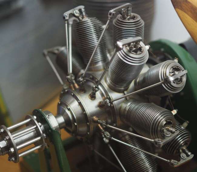
a few years ago I asked for some information for this engine. I saw it on a video.
Many problems ( no time, other projekts....) had stopt it.
Now I have all informations I need an I try to build this wonderfull engine.
I have the original plan, the building history from model engineer and 100 photos from building this engine.
Today I negotiate for castings.
There are many questions an I hope someone could help me here.
First I want to build the valve guide.

The red section shows my problem. First I must finish a tool for .437 DIA. But how could I turn the section between this DIA and the .190 drilling ?

Sorry for my bad english.
I hope you could understand me.

Rudi
 

Attachments

  • 38BEEB85-1A1B-4A8F-B425-8CCFB71556C4.jpeg
    38BEEB85-1A1B-4A8F-B425-8CCFB71556C4.jpeg
    90.9 KB · Views: 404
Last edited:
His engines are stunning, a number are on show at the Shuttleworth Collection, I took some pictures to share

The 14 cylinder rotary is rather special
gnome-14-rotary-5th-scale-02.jpg


Best regards, Nigel
 
There are no words to describe this engines. They are perfekt.
 
First I've never made the engine so this is just my thoughts...
Out of context its hard to say without seeing the assembly for that section. What is the purpose of the .437 diameter? Why is it chamfered from there to the .190 diameter? Is it important or is it drawn from an "as made" point of view? Does the .437" diameter hold an o-ring or similar? The inside angle and thickness at the tip does not have a dimension so not important?
2 choices - build it as drawn or as you think it needs to be.

My first impression is the inside angle is not important if no dimension is shown, so make the .437" with a small grooving / boring bar, and the angle shown is the land of the 118 degree tip of a drill from making the .281 opening (with detail omitted for the little bit that would not be taken by the drill being smaller than the .437" groove) - see my first image.

My second though /guess is that a custom bit is ground to finish that area. A custom tool can make it in the opening and work to make the groove and angle all in one...probably the way to go seeing as you need a very small tool for the groove anyway. (2nd and third images).

drill-thru-0281.jpg 59deg-full-taper.png tool.jpg
Mike
 
Hallo, I have used all your tips. Here is the result.


upload_2019-11-20_18-55-46.jpeg

upload_2019-11-20_18-57-20.jpeg
I think, I can use this part.
 

Attachments

  • upload_2019-11-20_18-56-47.jpeg
    upload_2019-11-20_18-56-47.jpeg
    50.1 KB · Views: 217
Here are the next parts.


upload_2019-11-21_19-53-42.jpeg


upload_2019-11-21_19-53-42.jpeg
 

Attachments

  • upload_2019-11-21_19-54-35.jpeg
    upload_2019-11-21_19-54-35.jpeg
    17.8 KB · Views: 143
Hello,
I am trying to find a set of plans for this engine, the Gnome. Stephen Wessel and Les Chenery seem to be the sources for plans but I have not been able to track down a contact or source for either. If you know where I can buy a set of these please let me know.

Bob
 
Almost immediately I got a very detailed email response of plans available with costing. Thanks again!
 
04B14C2C-A558-4430-BE65-1BA744991DF0.jpeg
Hallo, I am waiting for my castings an I have startet my 3D printer for fun.
In January I will get first models for the engine. It is made by sand casting from a profession foundry.
Now I’m printing cylinders for the model.
 

Latest posts

Back
Top