Old School Sawmill Edger

Home Model Engine Machinist Forum

Help Support Home Model Engine Machinist Forum:

This site may earn a commission from merchant affiliate links, including eBay, Amazon, and others.
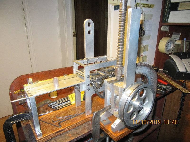
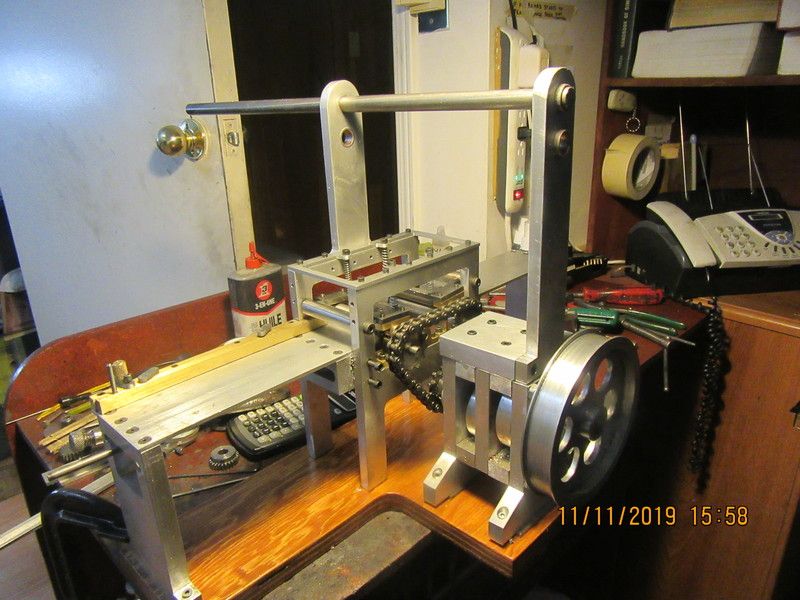
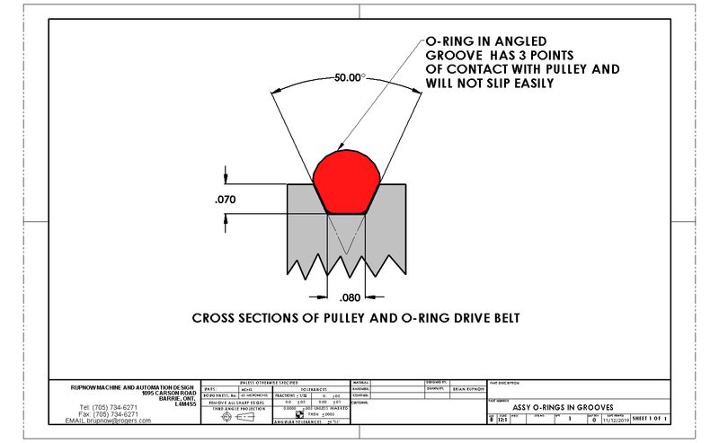
I have an issue. The roller chain that connects the reducer output sprocket to the two textured rollers has no method of tensioning the chain. That's okay, because I can adjust the tension by moving the entire reducer up or down by using spacer blocks until the correct chain tension is reached. (Note that the actual chain itself is not shown in this model.) The problem comes from the fact that the overhead shaft bearing support which is bolted to the reducer moves up or down as the reducer does. The other bearing support which bolts to the side of the edger frame does not. This is a perfect application for self aligning bushings, which are a two piece affair, where the bushing has a spherical outside and the housing it sets in has a spherical inside, but a normal round outside diameter. I need four of these, to support the two 1/2" diameter overhead shafts. There are other things that I can do, but not as neatly as these self aligning bushings would allow. I'm looking for a source for these self aligning bushings that are inexpensive and available in Canada, and I haven't been able to find one.---Brian
WCGvc2.jpg
 
Wouldn't it be simpler to put in a Delrin rub block to tension the chain? That is if you've got the room? Some of the old farm equipment that my Dad had used oil soaked hard maple blocks for chain tensioners on the low speed stuff and they lasted for years. The block would eventually wear out, but then again your not exactly building this thing to run untouched for years on end.

Don
 
Don--Thanks. I actually did think of that. I'm just looking at a couple of different things right now, haven't made up my mind yet.---Brian
 
That seems to work out just about perfect with the #35 chain in place and 1/4" of spacers underneath the gear reducer. I am going to make a plywood sub-base to mount the edger and the reducer to, as seen in the previous post. I can then fine-tune the spacers to give the proper chain tension.
RhuoLT.jpg
 
It keeps growing and growing---Tomorrow I will build the plywood sub base and get everything anchored to it before I start messing with shafts and bushings. I haven't built any of the anti-kickback system, but I do have holes drilled and tapped on the infeed side of the main frame. My kid who works at Fastenal is supposedly getting a piece of 1/16" square keystock for me---if he remembers.
dohk5d.jpg
 
Brian, if you're still looking for some cheap self aligning bushings you might want to consider cheap rose-joints (also known as rod-ends). I'm sure you could machine the base down into whatever mounting you need and they should be available in a range of sizes for not a lot of money. They won't handle super high speed but for low speed applications they should work fine.
 
Brian . What is the biggest size of the mounting bracket you can accept for the self aligning bushings ?
I'm thinking of the input shaft of a snowblower auger at the back behind the auger pulley . Also on the older home furnaces some of them used self aligning bushings on the fan .
 
Bill and Cogsy--Thank you for the ideas. The aluminum uprights that support the shafts are only 1 1/2" wide, so that is somewhat my upper limit dimensionally. I did consider the rod ends, and they are fine for self alignment, but the inner part is not bearing material.
 
I just spent an hour trolling the internet looking for self aligning ball bushings to use for the two 1/2" diameter overhead shafts. My conclusion is that while they might be the perfect thing for this application, they cost more than I am willing to pay. (Which is not that unusual.) I do have a trick that will allow the shafts to turn freely and costs me nothing. Since the gear reducer and the upright attached to it are free to move horizontally +/- about 1/8" and vertically +/- .030" without affecting the way that the roller chain mates with the sprockets, I can drill and ream both of the uprights for 1/2" i.d. oilite bronze bushings, insert the shafts, and let the position of the shaft actually determine where exactly the gear reducer has to set. I will post more about this when I get the edger and gear reducer positioned on the base which I currently have under way
 
I believe this is going to be a beautiful thing. I have been busy the last two days building some small fixtures for a customer, but stopping to add another coat of clear to the plywood base every time I could. This is the first time I have actually set the edger and gear reducer on the base, and I'm happy to see that everything fits the way I had planned.
fdswfd.jpg
 
Found out a few things today. The roller chain is about the right length with 1/8" shims under the gear reducer. I tried adding a half link to the chain length, but that made the chain too long and it was still slack with no spacers under the gear reducer. I dummied up that big pulley on the gear reducer and drove it with an o-ring belt from my electric drill. Everything goes round and round which is always a good thing. I have to put some 0.020" or 0.030" shims under the bearings on the infeed textured roller so the roller sets marginally higher than the top of the infeed table. Right now it is only about 0.005" higher and can't get a good grip on the board to send it through the saw. I picked up my oilite bronze bushings for the two overhead shafts today from Princess Auto. (You can see one of them setting on the infeed table.) I will cut the bushings to the correct length tomorrow and install them in the tower that is bolted to the edger frame. Then I will put a 1/2" shaft through and mark the tower above the gear reducer to see where the shaft center actually falls.
TpD6MY.jpg
 
Last edited:
The best laid plans of mice and men---When I built that gear reducer ten years ago, I attached the gears to the shafts with Loctite. Not very smart, but I was a newbee at the time. Now it seems I have to disassemble it all and pin the gears or add set screws to them. Phooee!!!
 
Things weren't quite as dire as I had thought. Nothing has let go in the gear reducer. The roller chain sprocket that I have on the reducer output shaft has been sleeved down to 1/4" diameter from 3/8" diameter. I forgot to drill and tap new set screw holes, so even though the set screws were tightened they were only bearing against the sleeve, not the output shaft. I have both uprights drilled and reamed for 1/2" shafts, and they seem to be fine---with all the bolts tightened up the shaft still spins. The roller chain is a bit tighter than I expected it to be, so the 1/8" spacers underneath may have to become .150" thick, not the .125" that they are now. Some of this stuff you just can't tell until all the bolts have been tightened up.
8VGRWN.jpg
 
Brian, this picture below just makes me happy to look at it. I think they call it tool or machinist porn but for some reason the recessed screws and such are just pleasing to stare at. good job.

upload_2019-11-12_10-3-17.png
 
Werowance--Hard to slide lumber over the tops of socket head capscrews. The plate is only 1/8" thick so a counterbore wouldn't work.
Today was o-ring pulley day at my house. Looks like tomorrow may be an o-ring pulley day too. Four down, three to go. I have ground a tool bit to the profile I wanted, so all grooves are plunge cut to a depth of 0.070". I am hoping to achieve the result shown in the attached drawing, which means that the 1/8" cross section o-ring will pick up traction from the sides of the pulley as well as from the bottom. The picture of the tool I ground isn't that great, but it has an 0.080" flat on the tip and an included angle of 50 degrees. There has been a raging blizzard here all day, with about 6" of new snow on the ground and 6 more on the way overnight and into tomorrow. No fat-mans walk today. I'm down 42 pounds since May, and have 8 more to go. May be walking in the mall until snowmobiles have packed down the snow in the bush-trails I generally walk on.
bfdk1l.jpg

8FeLio.jpg

9JCRME.jpg
 
Four three-grooves, two two-groove and one six-groove. I only see one three-groove in the drawing up top, and there doesn't appear to be a use for the outer three grooves on the sixer, so I wait with curiosity to see how this all goes together!
 
Back
Top