Old School Sawmill Edger

Home Model Engine Machinist Forum

Help Support Home Model Engine Machinist Forum:

This site may earn a commission from merchant affiliate links, including eBay, Amazon, and others.
Run, run--fast as you can
You won't catch me, I'm the Pillow Block man.
Dang, there was a lot of time to make ten of these things!!
rIjPtE.jpg
 
Actually Don, oil holes will be added. I was more interested in getting them all finished. I still have to polish them up, and I will add the oil holes then.---Brian
 
YES!!!--First assembly. Everything fits and most of the bolts go in. Milestone event!! It's plain that I will have to open a few clearance holes, but all in all I'm very pleased. The true story will be told when I make the two cross-members that bolt the two side-frames in place. It's been a long day.---Brian
6InEyg.jpg

oxzmfo.jpg
 
From what I have read, these edgers had a habit of "kicking back" a board and wounding the operator who was setting the board on the infeed table and pushing it through until the infeed roller grabbed it. I don't want any workman's compensation claims in my mill, so I have added a set of anti-kickback fingers to the assembly.
UyCeVG.jpg
 
A change to the top-plate. I was going to make it from clear Lexan, but then today I remembered how sawdust sticks to lexan because of it's electrostatic properties. Top plate will now be made from aluminum.
pdZpnK.jpg
 
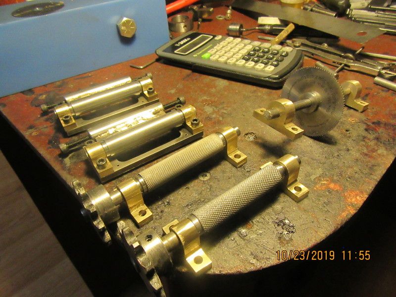
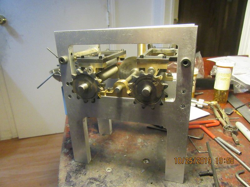
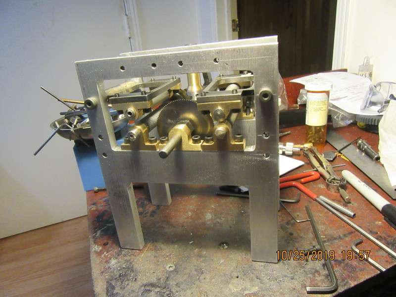
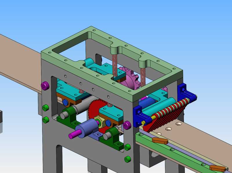
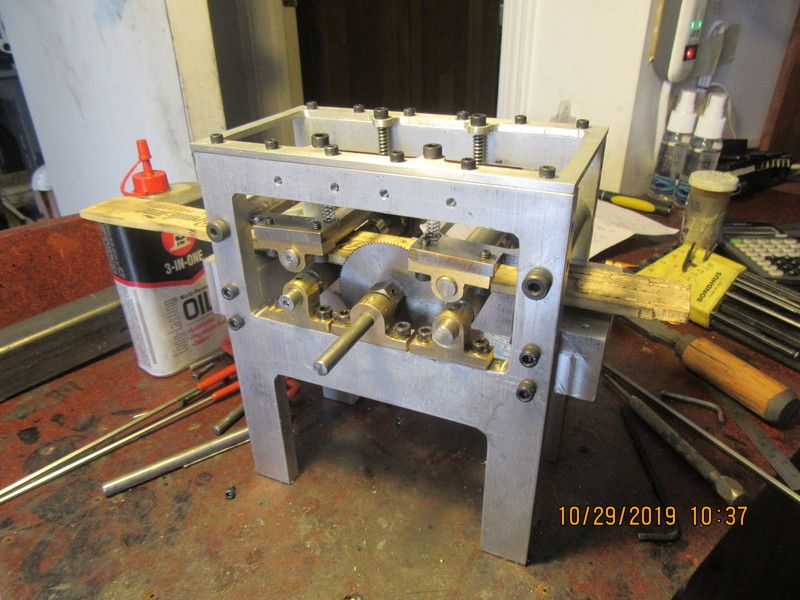
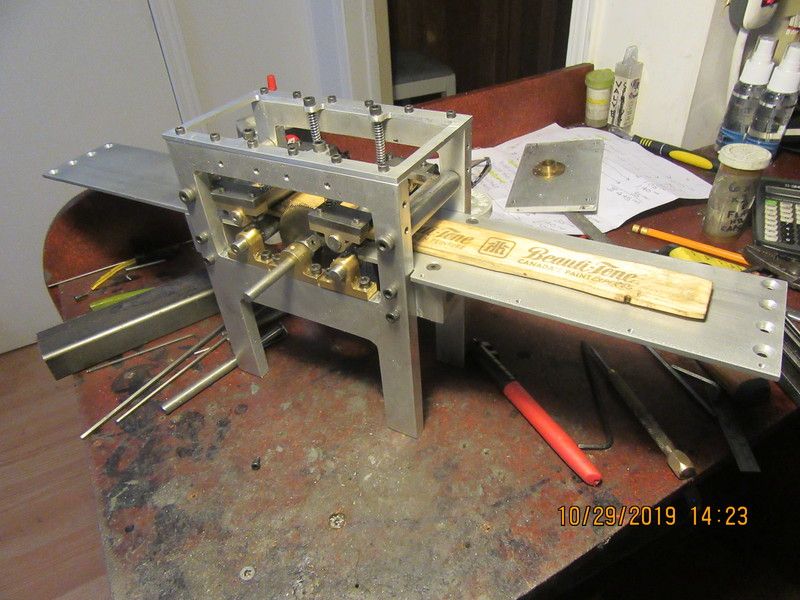
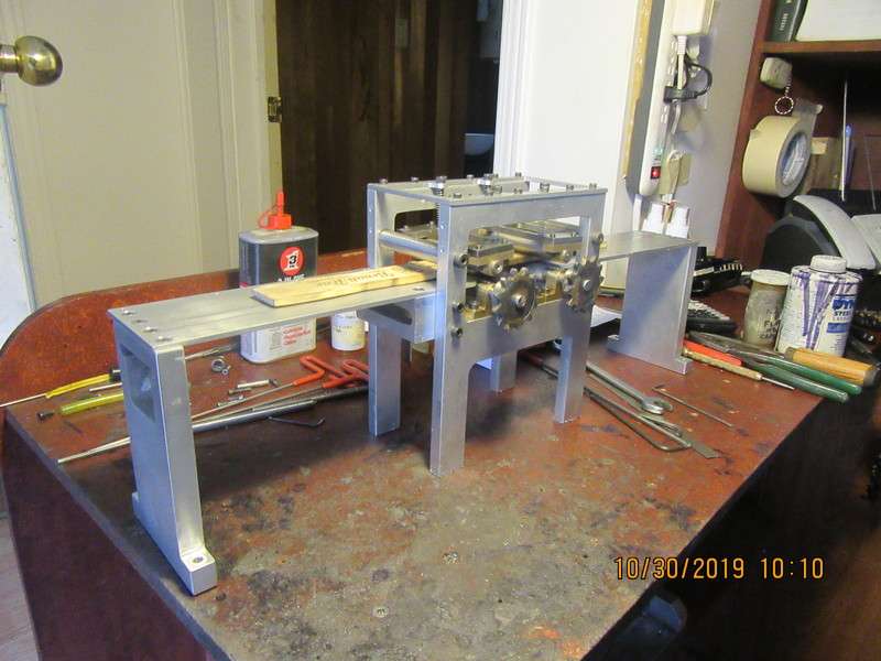
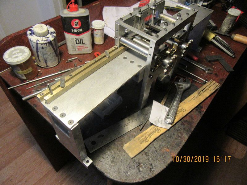
I spent a large portion of my morning "fine tuning" my "pillow block" bearings. Real pillow block bearings are self aligning, whereby the actual bearing unit can orbit in the cast iron housing to prevent any binding. My one piece simulated pillow blocks weren't nearly as forgiving. When they were tightened down to the aluminum frame, the shafts were binding very badly and wouldn't rotate. The misalignment was very small. So small that conventional machining wouldn't / couldn't fix it. My reamers are too short to span across both sides of the frame. I ended up coating dummy shafts with #600 aluminum oxide paste and lapping (for lack of a better word) with my electric drill. The dummy shafts were, of course, made long enough to span across the frame and fit through two opposing bearings at once. During the process I removed the bearings one at a time for polishing and the addition of "oil holes". Final step was to remove bearings one at a time for a bath in laquer thinners, then scrubbed inside with a small brush to remove any remaining grit. Doesn't sound like much, but it eat up my morning. Yesterday it rained all day, and I missed my "Fat mans walk". Today was lovely here, so I walked much farther on the forest trails where I hadn't been before to make up for the missed walk yesterday. It was about 58 F today, and many of the leaves have fallen, but enough remain on the trees that it is still very pretty. Seen a lot of new ground, and my legs are telling me about it tonight.
 
So, here we are with the new top plate and all of the bearings freed up. I put a stir stick into the edger just to see how it looks. The springs on the pressure rolls aren't strong enough, but they are out of a kit I had with about a thousand springs in it. I will buy stronger springs next time I'm downtown. I think that now I can go ahead with the infeed and outfeed tables and their end stands.
SHPIwx.jpg
 
The infeed and outfeed tables are finished and installed. The infeed table position is perfect. The outfeed table is a few thou. to high, which means that the powered roller on the outfeed side is not getting a good grip on the wood. It's an easy fix. I will take 0.025" off the top of the cross strut that the outfeed table attaches to. tomorrow I will make the end stands.
44nxXt.jpg
 
So, after far more time than I thought it was going to take, we have an adjustable fence. I haven't yet put the locking mechanism in that makes the moveable fence hold it's position. Adjusting the position of the fence allows the edger man to determine how much he actually wants to trim from the side of a board.Guess the locking mechanism will be tomorrows job.
UsANx0.jpg
 
Not an awful lot to show for today, but we do have a lock for the offset fence position. Tomorrow will be the day to clean all the bits and bobs for the adjustable fence up and "final assemble" them.
RMOcJL.jpg
 
This morning I finished the hub for the moveable saw-blade. The hubs are two part, with 3/8"-24 threads on them. That scrim of Loctite that you see has to be cleaned up after lunch, and then I start work on the shifter link that moves the saw right or left on the shaft, to cut wider or narrower boards.
fpSGQT.jpg
 
Today we have something very slick!! The man running the edger has to look at each board he puts through the edger, and estimate how wide he can make the board, and still not leave any wain (bark) on the edges. For the side of the board closest to the fence, he can move the adjustable fence in or out. For the other side of the board, he must be able to move the other saw closer to or farther away from the stationary saw. I've just finished with the mechanism which moves the non-fixed saw, and it is so neat I figured it was worth a short video.

lbwPXB.jpg
 
Hi Bill Payne--Good to hear from you. thank you Jlchapman.
I'm having a lazy day today. I used my broach to put a 1/16" keyway thru the hub of the moveable saw blade, and milled a keyseat in the saw shaft. I have to try and find some 1/16" keystock tomorrow. This is a tricky business, because although the key must be there to transfer torque from the shaft to the blade, it must still allow the sawblade and hub to move along the length of the shaft as shown in the previous post to let the edger-man set the distance between the moveable saw and the fixed saw to select the width of board he wants to "edge".
rrHmXx.jpg
 
This mornings work was to machine a "cap plate" for the gear reducer, and the riser which will support one end of the overhead shafts. The reducer output shaft was shortened, and a sprocket which formerly had a 3/8" bore was "sleeved" to go on the 1/4" reducer output shaft. I am rapidly approaching the point where I have to make a firm decision on whether I use toothed belts and pulleys or machine my own pulleys from aluminum and use rubber O-rings as drive belts. Seeing as I just spent over $500 yesterday for a new milling vice, I'm pretty sure what the answer is going to be.
kLyQWg.jpg
 
An executive decision has been made. I'm going to make my own pulleys and use o-ring drive belts. Originally I had all the pulleys at 2 1/2" diameter, but I have changed that to 2.0" because that is what stock I have. I have stolen the 25 tooth gears off of the reversing winch, because I doubt that I will ever use the reversing winch again.
 

Latest posts

Back
Top