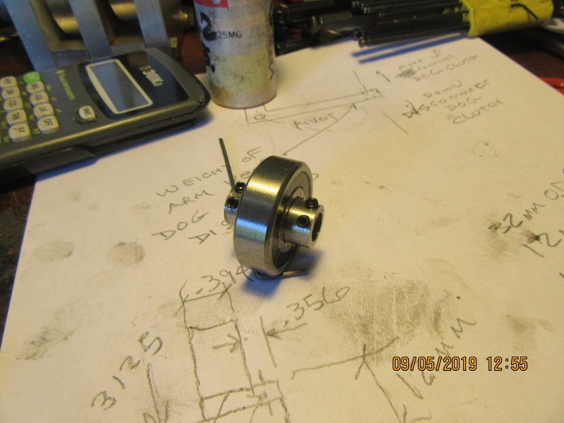
Today I received my one way clutch bearing in the mail. It looks exactly like a sealed ball bearing, but it definitely has the "turn only one direction" feature. I am going to mount it in the offset weight arm, so that as soon as the engine has lifted the weight arm over the top, the arm will swing back down due to gravity, and having no "binding force" transmitted back to the engine.

Verical hit and miss engine
- Thread starter Brian Rupnow
- Start date


Help Support Home Model Engine Machinist Forum:


Similar threads
Latest posts
-

-

-
-

-
-
-

-
-
Just joined. Have inherited an Emcomat 7. Has a few issues so seeking knowledge
- Latest: Niels Abildgaard
-
