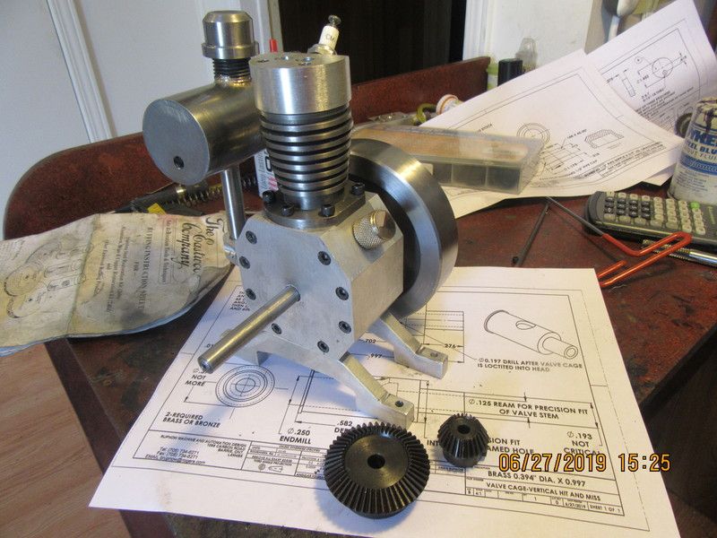
The port holes which get drilled into the head will not be done until after the valve cages have been made and installed into the head. Then the cylinder head and the hole in the side of the valve cage are both drilled at the same time.

You are using an out of date browser. It may not display this or other websites correctly.
You should upgrade or use an alternative browser.
You should upgrade or use an alternative browser.
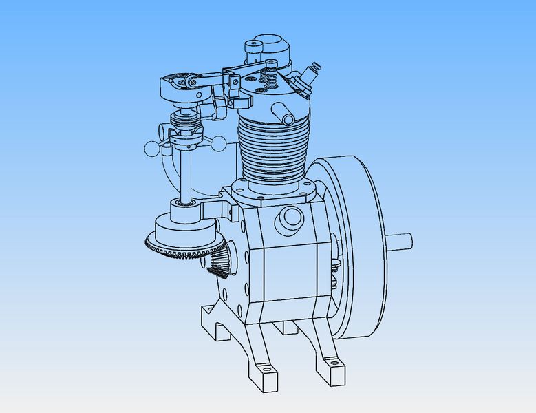
Verical hit and miss engine
- Thread starter Brian Rupnow
- Start date


Help Support Home Model Engine Machinist Forum:
This site may earn a commission from merchant affiliate
links, including eBay, Amazon, and others.
I have a stick of 7/8" bronze that I bought a while ago. I don't know exactly what composition of bronze it is, but it's nasty stuff to machine. However, it did work quite well for an oil filler cap. You can't see it, but on the 3/8"-16 threaded shank there is a cavity .030" deep for a 1/16" cross section o-ring to prevent oil from leaking out. Also, my $20 mitre gears came today, and they look quite good. The bore on the smaller gear looks a bit too small to me, so I may open it out to 5/16" diameter.
- Joined
- Sep 2, 2011
- Messages
- 1,342
- Reaction score
- 360
Brian, mounting aluminum in the vice like that do you have trouble with it wanting to walk or move on you and also do you have trouble with making flat spots -referring to the head? whats your setup and words of wisdom on this if not taking away to much from your build
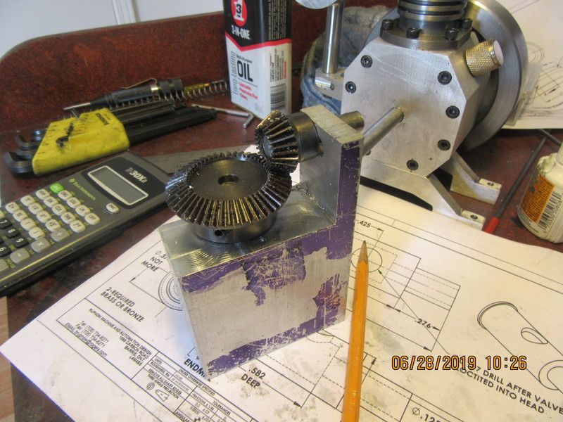
Whenever I buy bevel or mitre gears, they are never supplied with the dimensional data on how to set them up for a proper mesh. I can figure it out using the center finder and read-outs on my milling machine, but I always have to make a test block and put the holes for stub shafts in the right position to really confirm my numbers.
Werowance--I never have problem holding aluminum in my vice. Nor do I have any problem with it moving. Check that your vice jaws are perfectly parallel to each other, always position the part you are holding equal distances from the ends of the vice jaws, and use spray on WD40 as a machining lubricant for aluminum.
Sometimes ya just don't know--how big things are going to be until you have them "in hand". My bevel gears came yesterday from somewhere in China. They look great, they are well made---but--They look too big to really please me. They are big enough that I think they overshadow the engine. Of course this doesn't show up until you have modelled them and put them into the overall assembly. Now I have to decide whether I go ahead and use them, (they are 20 and 40 teeth) or reorder the next smaller set which are 15 and 30 teeth. I still have to make valve cages, valves, piston, con rod, a crankshaft, and a carburetor. And I'm scheduled for cataract surgery on 15th of July and again on the 29th of July. The gears are not expensive at only around $20 for the set. This shows the current gears that came yesterday. I have decided while typing this that I will go ahead and order the smaller gear set. Time is not supposed to be critical on this engine, and I think it may look better with a smaller gear set.
There's nothing quite like having the parts in your hands - or ready to mount - for getting their size to sink in. At least for my brain.
I may try something different here, and actually buy a set of two cast iron piston rings. My previous attempts to make my own have not been successful, so will try a purchased set. However, my Google-foo isn't working very well this morning. Can somebody please recommend a supplier of 1" piston rings in North America. I am ready to make a piston now, but if I do buy a set of rings for it I would much prefer to cut the ring grooves while the piston is set up for turning the outer diameter.---Brian
Last edited:
cheepo45
Member
- Joined
- Dec 22, 2010
- Messages
- 278
- Reaction score
- 131
Hi Brian,
Try Otto Engine Works http://www.ringspacers.com/
They have all kinds of rings available - Reasonable prices also.
Scott
Try Otto Engine Works http://www.ringspacers.com/
They have all kinds of rings available - Reasonable prices also.
Scott
Thanks Cheepo45--I have just sent them off an email.---Brian
After a long and eventful war with Paypal, I ordered the rings from the source Cheepo suggested.--thank you.
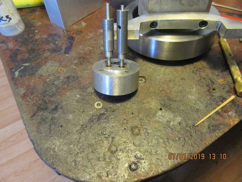
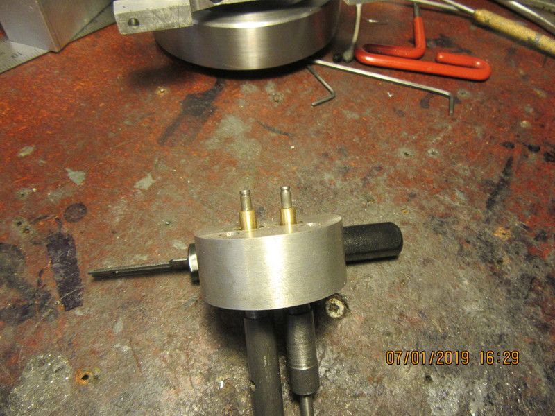
After a two day break from machining, I came down to my shop this morning and made two brass valve cages and two 1018 cold rolled steel valves. I haven't trimmed the valves to length yet, as I have to drill the 0.039" cross holes in the valve stems for spring retainers, and still have to lap the valves into their seats, which are part of the cages.
OK - this is the part I need to watch closely.
Don't spare the pictures - if you don't mind.
Don't spare the pictures - if you don't mind.
CFLBob--What specifically did you want to see?
I'm trying something a little different here. I have always, in the past, drilled a 0.039" cross hole thru the end of the valve stem for a short piece of 1 millimeter round stock to keep the spring retainer from flying off. Last year I bought a hundred 1/8" circlips and 100 3/16" circlips, and I also bought the special tools to install them. The tools are really great and make installing the circlips very easy.--So--This time I have put a 0.025" wide slot in the ends of the valve stems and I will be using circlips instead of the 1 mm round stock.
CFLBob--What specifically did you want to see?
To be honest, I think I can see what you do. I'd just like to look over your shoulder and make sure I'm thinking correctly.
You have two valves that are not cut off. You turned the stem down to its diameter. Then you turned the valve itself to diameter and shaped the fillet between the stem and the valve seat (that's a radius, right?) where the seat will contact the valve cage. You left that turned diameter rather long (half inch??) in case you have to cut away the fillet and start over. I think you put 320 grit grinding paste between the valve and cage then spin the valve on its long axis. With a drill? Slowly or fast? From the stem side or the barely turned stock side? Once the fit is good, you switch to 400 grit paste and finally to 600. Once that's complete you pull the valve (clean it off) and put it back in the lathe. Then you part off the extra steel and face the valve.
Am I really far off base?
You've got most of it. Before you even start to machine the valve, drill and ream a hole to exact valve stem size in a piece of material about 1/2" long. This will be your diameter gauge. Then start with 3/8" rod at least twice as long as your valve , turn it to 5/16" . This gets around the fact that 3 jaw chucks never run absolutely true. You can't turn the entire length down in one shot, because it becomes too flexible as the diameter decreases. So, if the length below the head is 1.2" long, you break that up into 3 equal segments each 0.4" long. Turn down the first segment to about +.003" over finished diameter. Be careful not to go undersize, as then you will have to start over again. Then repeat with the second 0.4" length. Then repeat with the last .4" length. At that point, set your compound slide over to 46 degrees. (That is because you want to end up with an included angle of 92 degrees on the valve). Then take successive cuts from the stem diameter outwards until you have a finished valve. There is no radius nor transition. The valve now goes directly from .003" over finished diameter to the angled face. Now you start with the 220 grit sanding strips, holding one end of the strip in each hand with the strip looped around the valve stem. Do NOT knock your fingers on the chuck jaws. It hurts. Be prepared to let go immediately if the sanding strip wants to pull out of your grip. Work the sanding strip back and forth over the full length of the stem--the lathe is running while you are doing this. Stop approximately every 20 "strokes" from one end of the stem to the other. Now is the time to use that diameter gauge that you made in the very first step. Shut down the lathe and see if the gauge will slide over the valve stem. If it does, then great. You want a nice sliding fit over the full length. You don't want it sloppy, but you don't want tight spots in it either. It never ever fits over the stem the very first time. You keep repeating the last two steps over and over, until it does fit. This is a long and drawn out pain in the ass procedure, but it makes great valves. Once the gauge does fit properly over the full length of the valve stem, you are ready for the next step. Don't part the valve off from it's parent yet. The parent part gives you something to twirl back and forth between thumb and finger. Never use power tool to do this. only finger power. Coat face of valve with 400 or 350 grit grinding paste, push the valve all the way into it's seat, and twirl it back and forth (lift it up about every 15 twirls (Twirl is a semi rotating back and forth movement.) Don't always twirl in same place--every time you lift it off the seat (in the formentioned 15 twirls) rotate it about 30 degrees, because you are trying to "work" the entire face. Don't get any compound down into the guide area on the stem--you don't want to lap away the good fit down on the stem. After you have done this until your finger and thumb go numb, clean away all traces of compound, apply 600 grit, and do it all over again. I am assuming that you have already prepared the valve seat with something similar to the wonderful George Britnel tool, which leaves a true 45 degree seat, perfectly concentric with the guide portion of the valve cage. Note that the seat now has an included angle of 90 degrees, while the valve face has an included angle of 92 degrees. That is because you want a "line contact" between the valve face and the seat to begin with before you begin lapping.--and you want that line contact at the extreme outer side of the seat, not down in the bottom of the cone. After you have gone thru all of the above, and are somewhat confident that your valve will seat air-tight with the seat in the valve cage, you can part off the valve from it's parent part. Leave at least .025" of material above the taper because if you part off at the taper and leave a knife edge on the head of the valve, it will burn up from the heat of combustion. Match mark which valve goes with which seat at this point, because if you mix them up bad things will happen. There are other more exotic things that you can do with the valve machining that will improve flow in infinitely, unmeasurable amounts but I don't do them because there is too much chance of screwing up the valve and having to start over. One more very important thing--when you first put the material in the lathe chuck, make sure you have sufficient length to make the valve sticking out beyond the chuck jaws. You do not want to have to loosen the chuck off and pull more material out. All turning should be done in one set-up.
Last edited:
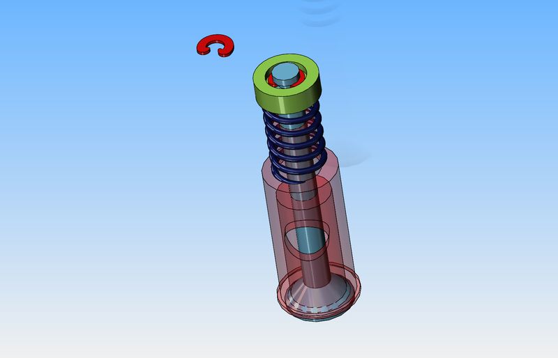
I said in my earlier post that I was using circlips to hold the keeper and spring in place on my valves. After a check of the names of these things, it seems that they are called "e-clips". They are small---Very damned small. Knowing the disaster which will be caused if one of these things flys off, I have redesigned the keeper plate. It now has a recess in the outer face, 3/16" diameter x .035" deep. The e-clip fits right down into the recess and can't fly off.
Thanks for the in-depth summary. I really appreciate that. I've copied it off to my computer where I'm keeping notes on this process.
I'm going to modify all the dimensions to fit the Webster; the valve and stem diameters are 0.250 and 0.093 for example. The basic design uses valves in valve cages, though, so it seems natural for this. Unfortunately, I'm a long way from doing this.
I'm going to modify all the dimensions to fit the Webster; the valve and stem diameters are 0.250 and 0.093 for example. The basic design uses valves in valve cages, though, so it seems natural for this. Unfortunately, I'm a long way from doing this.
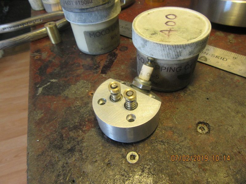
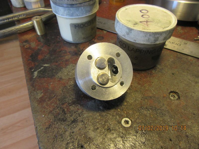
The valves have been lapped and cut away from the parent material. Valve spring keeper plates, valve springs, and e-clips have been installed. Valves have been match marked so I don't mix them up. I may have to play with spring strengths when I get farther into this, but those springs were ones I had in a "kit". Whatever type of clip this is, it should work well when setting down in a recess in the spring retainer as you see here.
Similar threads
- Replies
- 413
- Views
- 38K
- Replies
- 148
- Views
- 22K
- Replies
- 5
- Views
- 2K
- Replies
- 6
- Views
- 781