Verical hit and miss engine

Home Model Engine Machinist Forum

Help Support Home Model Engine Machinist Forum:

This site may earn a commission from merchant affiliate links, including eBay, Amazon, and others.
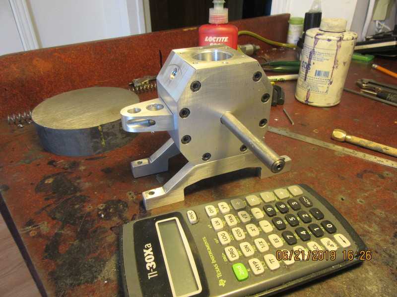
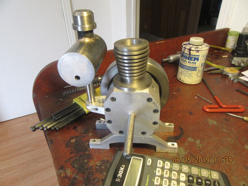
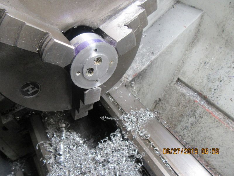
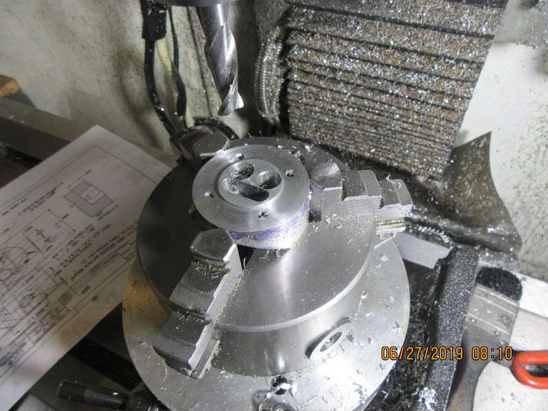
At the very last moment, I decided to put an o-ring groove in the top of the main body. This engine will have a "wet" crankcase, and it's either go with an o-ring or put a gasket between the main body and the cylinder to prevent oil leaks.
VYYkk5.jpg

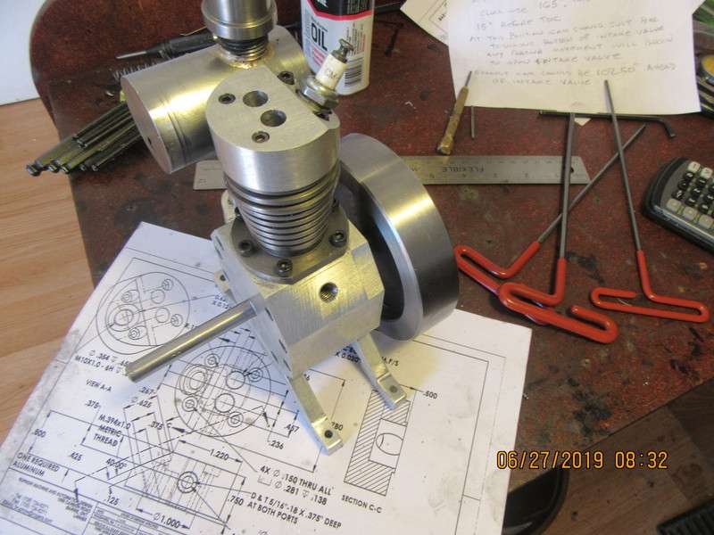
As soon as I saw the closed crankcase design, I wondered if you were going to build a wet crankcase with a con rod “splasher” for lubrication.

Looking good Brian, another cool build!!!

John W
 
I don't really think the con rod needs a "scooper" on it. If there is enough oil in there for the bottom of the con rod to hit on each rotation, the oil will certainly get to the crankshaft throw. In fact the entire crankcase will be filled with a very heavy oil mist. I am depending on that oil mist to also lubricate the wrist pin.
 
It was a lovely sunny day here today---and I couldn't think of a single damned thing to do outside. Good wife didn't want to do anything. So---After my fat mans walk, I spent the day building a gas tank. It turned out okay, other than the fact that the end of the 7/16" post ended up undersize by about .015". I knurled it to bring it up to a larger diameter. It is supposed to be a "snug" fit into the bracket bolted to the side of the engine. The post and the filler neck are silver soldered to the main tank body. The tank body is counterbored on both ends, and a piece of 1/2" thick plate is J.B. Welded into each end. I will let it set up for 24 hours, then spend a bit of time polishing out any imperfections and drill/tap one end for a fitting.
nWlQ67.jpg
 
I was just about ready to change out my lathe chuck jaws to start machining the flywheel. I wondered "What else do I have to machine with these current jaws?"--An ignition cam!!!--So, a cam was made this morning and the cam and points were installed on the engine to make sure everything fit properly.---It did. Good wife just showed up and asked for help cleaning some rooms. Flywheel will be started later.
uHYCuh.jpg
 
Here we have flywheel #1--A piece 1 3/8" long cut from a 4 1/2" dia. billet of steel. First set-up is with reverse jaws in the chuck, not worrying about centering at this stage. Flywheel material has been tapped on the face with dead blow hammer to make certain it is "seated" against the three contact surfaces on the far side of the face you see.
TI7ip7.jpg
 
Flywheel-2 First a couple of facing cuts across the entire face to get rid of the saw cut (saw cuts are never quite square to the central axis of stock.) After facing, drill and ream the 3/8" center hole completely through. Since the 3/8" center hole is not large enough to allow entrance of one of my heavier boring tools, I put a 5/8" endmill in the tailstock chuck and cut to the depth of the recess I want, which is 0.438" in this case. Then with my lead screw in reverse I start at the center and cut out towards the rim, taking 0.020" depth of cut each time. The 0.428"step" is where I am going to grip with the chuck jaws in my next set-up. This will allow me to turn the outer diameter just enough to clean it up. The recess in the other side of the flywheel is relatively small, so I will probably cut the recess in the same set-up, thus keeping everything hopefully concentric.
jwOGVx.jpg
 
Flywheel-3 Flywheel has been flipped around 180 degrees, gripped on the inside of the .438" recess created yesterday. That allowed me to take a cut on the outside diameter to clean it up, and allowed me to put the recess in the side which is now exposed. All of the major machining is now finished. There will be a bit of polishing, and I still have to cut the keyway and drill/tap a couple of holes thru the hub for set screws.
gtlnM8.jpg
 
I don't really think the con rod needs a "scooper" on it. If there is enough oil in there for the bottom of the con rod to hit on each rotation, the oil will certainly get to the crankshaft throw. In fact the entire crankcase will be filled with a very heavy oil mist. I am depending on that oil mist to also lubricate the wrist pin.

I always tend to forget the scale of the models being built! With that tiny crankcase, there should be no problem regarding splash.

This ain’t no damn 6 1/2 horse Briggs and Stratton!

Can’t wait for the next installment, and of course, the first run!

John W
 
So--Gas tank and flywheel are mounted on engine. The flywheel is just posed for a picture. It still has to have the keyway and set screws added. Things look a bit out of proportion right now, but once the cylinder and cylinder head are mounted it will look more like an engine.
1HRKbc.jpg
 
Cylinder head-1 The cylinder head has a finished diameter of 1.780" and a length of 0.800". A piece of 2" diameter stock was purchased and cut to 2 1/2" long. The chuck jaws extend out 1.25" from the face of the chuck, and I need some space between the jaws and where the turn down ends. Both ends were faced to be "square" with the central axis, and then the turned down area was turned to 1.780" diameter 1 1/4" long.
7oGsqZ.jpg
 
Next step was to mount the piece in my mill vice. Normally I would have a v-block on one vice jaw, but the 2" diameter piece was too big to allow for a v-block so I just mounted it between the jaws, setting firmly on the floor of the vice. Four bolt holes were drilled and counterbored, and the valve guide holes were drilled and reamed. The piece finishes off at 0.8" thick, so I made sure to drill at least 1" deep. Next step was to tilt the vice at 40 degrees to mill the angled part of the head and drill/counterbore the sparkplug hole. It is drilled blind at this point, and since I only have a tapered tap for the metric sparkplug hole I won't tap the hole until I have put the recess in the far side of the head.
morFF9.jpg

lt3UGs.jpg
 
Cylinder head-3 Cylinder head has been parted off from the parent material, then flipped over and remounted in the 3 jaw chuck, to be taken down to finished overall height of 0.80" Once it is faced to exact length, the exposed face is machined 0.050" deeper, and a 1.00" spigot left in the center. Next step will be over to the rotary table to finish off what is now the exposed surface.
wn94dc.jpg
 
And now we reach the end. The cylinder head is flipped over and mounted in the chuck on my rotary table. It is centered under the quill, and I have a piece of 3/8" round stock turned to 11/32" on one end. I dial in the appropriate offsets as per the drawing, and YES--- the end of the rod fits into both previously reamed holes, simply by moving in the X axis on my mill. I put in a 3/8" endmill to cut the very slight counterbores at each reamed valve cage hole, then dial in the position of the slot which exposes the tip of the sparkplug and mill it 1/2" deep. Then the cylinder head is removed from the rotary table, taken out to my main garage where my bench vice lives, and I tap the sparkplug hole. Then a little clean-up, and mounted too the engine.
OGXfzo.jpg

ode00G.jpg
 
Back
Top