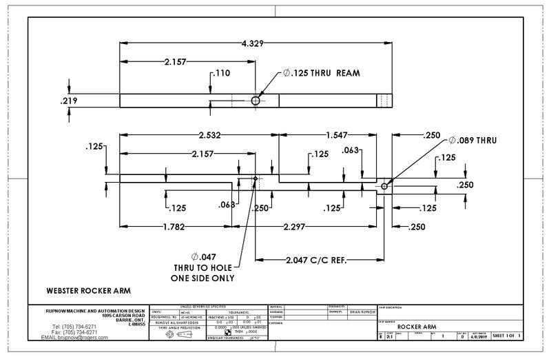
Werowance builds a webster

Home Model Engine Machinist Forum

Help Support Home Model Engine Machinist Forum:

This site may earn a commission from merchant affiliate links, including eBay, Amazon, and others.
Yes--They can be complete flats, making it a very easy cam to make. As a rule of thumb--if the cam follower is a round wheel or a lever, they can be true flats. If the cam rides against a flat tappet, there is a danger that each time the cam rotates the flat on the cam will "smack" against the flat bottom of the cam and cause problems.---Brian
 
The boring head method leaves the flanks curved rather than flat and is a very simple procedure. Once the first plunge cut is done, each subsequent cut only takes a tiny 'nibble' so can be done very fast. For single lobe cams it's the only method I use and gives a great result.
 
The boring head method leaves the flanks curved rather than flat and is a very simple procedure. Once the first plunge cut is done, each subsequent cut only takes a tiny 'nibble' so can be done very fast. For single lobe cams it's the only method I use and gives a great result.
Agree. This is the method I used since it seemed pretty straight forward. I used Brian's write-up as a guide, but rather than running the boring head in reverse, I made a right-hand boring bar and ran the boring head CW.
 
Last edited:
The cam looks a bit prettier with rounded flanks, but trust me--it is not necessary on the Webster. For a cam like the Webster needs it is perfectly okay to make a cam with flat sides, and is considerably less work.--However--If you do use a cam with rounded flanks, the engine will run just as well.---Brian
 
Thanks guys, the reason I am shying away from the boring head is because I am not comfortable with using the boring head yet. i just cant seem to wrap my head around how to measure where my start cut is (aka like i would find using an edge finder or an end mill and cigarette paper) and then how far i am tramming it over. i really need more practice with the boring head. i had watched Mr. Fellows youtube video of making a cam several times before i understood what he was doing but I'm just more comfortable with a plain old end mill right now.
 
cam making turned out good this weekend. and just got a start on the rocker arm last night.

upload_2019-6-4_9-24-49.png


upload_2019-6-4_9-25-14.png


upload_2019-6-4_9-25-37.png
 
help please. im still working on this rocker arm and its junk now. I cant upload pics from this pc but I have struggled with the drawings of this part all week. for some reason to me it seems every thing is drawn backwards and then there are some things that I think should show the dimensions but don't. then if I try to calculate the difference its at least .001 off one way or the other. when I show my miss cut it is way more than that but its just because I am struggling with the layout.

so help. if anyone has redrawn this part with more dimensions or anything could I please get a copy or a screen shot. sometimes just seeing it with all the measurements or redrawn really helps.


and thanks in advance.

edit- looking at the post above, its everything to the right of the center hole that I cant seem to get layed out properly

Hello mate,

Have you tried modelling this up in CAD yourself? I only ask as this always helps me when I can't get my head around a 2D drawing.

You can query any dimension then, and always go back to take another look at any point.

Cheers
Earl
 
I struggled for a while with the drawing also.

From the top view of Brian's drawing you notice that the squared end of the rocker arm is offset from the centerline of the cam end shaft in the direction away from the frame. That seemed wrong to me. Nevertheless, I built the rocker arm per the drawing and lined up the squared end of the rocker arm with the valve stem by adjusting the width of the rocker arm spacer.
 
thank you very much. that's exactly what I was needing. I was so agrivated last night about the mess up. maybe I can get one made this weekend. I really appreciate it Brian.
 
When I built my Webster, I modelled it all in Solidworks. Sometime over the years I had a computer crash and lost all the Webster files. It took me about five minutes to open the original Webster plans and make a model and drawing of the rocker arm. I'm glad I could help.
 
i really appreciate that Brian. I don't have any cad software and you saved my weekend. finally got it done Sunday night.

as promised picture of the failed one and then the final good one thanks to Brians drawings. this is actually rocker arm 3.0 and if you count the number of times I had to wipe off the dykem and redo then its rocker arm 25.0 :) I had a time with it until I finally figured out I was subtracting .063 instead of adding it like I should have at the tappet head. rocker arm 2.0 was just simply cut to short right off the bat.

I need to read some of the posts about the screw that holds it to the side support. wondering if it needs to be a shoulder screw or what? ill take a look and see what others did on their builds.

bad one:
upload_2019-6-10_8-57-27.png


and good one 3.0


upload_2019-6-10_8-58-24.png
 
so the plans call for a ss screw for the tappet tip to hit the valve. I'm wondering on that. wouldn't brass be more desired for smacking the valve tip? I ask because I believe I have some teeny tiny brass hex stock that should work well for that.
and then on that note. the plans don't call for it and I don't see it on other builds but how is everyone holding adjustment on that? a jam nut on the bottom, deformed threads, thread lock...etc.?

I was thinking jam nut
 
Open that 0.089" hole out and thread for a #6-32 or a #5-40 socket head capscrew. Grind most of the head away on the capscrew, just leave enough that you can still engage the hex with a hex wrench. Screw it thru the tapped hole and put a common hex nut on the far side. It doesn't need to be a jam nut. For the pivot hole, use a #5-40 or #6-32 socket head capscrew. Buy a longer one that is only threaded part way up the shank. Do some careful measuring and possibly a bit of threading on the bolt itself. You can make it so that the rocker arm rides on the unthreaded part. Use a bit of Loctite on the threads to keep it from backing out of the sideplate when the engine runs.
 
last night I opted to just have some fun in the shop so I decided to experiment on the rocker arm spring. I had saved a recoil spring from a Harbor freight Honda clone that I had to replace a while back and saved the spring. it was a little bit narrow per plans and also thick however I understand this is just fine but I also had a broken bandsaw blade that I wanted to see how it would work out. so I ground the teeth off of a short piece of the blade and then to the belt sander to bring on down to final dimensions. for thining it I tried flat sanding it but it would fling out under the guard so I just held the end of it and used the tip of the belt sander back and fourth saping out ends every little bit. lots of back and fourth dunking in water so as not to over heat it. in the end I had a piece about .018 thick which is a little thicker than spec but seemed springy (technical term) and then I bent it around a piece of .250 rod I had to make the radius. still have to drill the hole but other than that it turned out nice. so a good use of scrap bandsaw blades. and I had fun.

upload_2019-6-11_8-59-56.png


upload_2019-6-11_9-0-31.png
 
dipped it in some very well used ferric chloride to give it some color. a little copper deposited on it as well but it came out a nice dark color. looked almost black once I oiled it. and the copper doesn't show up hardly at all after some rubbing with oil.

upload_2019-6-12_8-54-7.png
 
Last edited:
I am also building a Webster in my down south mode (IE Michigan winters). Looking at Brian's and your build has
given me ideas and answered questions about my build. I have always had a problem with cutting fins or even parting
parts off with a cut off tool (lathe too wimpy). My solution has been to mount a 4 jaw chuck on a rotary table and cut
the grooves with a proper thickness milling cutter held in a arbor.
 
Back
Top