Longboy's "OVERTIME" I/C Twin!

Home Model Engine Machinist Forum

Help Support Home Model Engine Machinist Forum:

This site may earn a commission from merchant affiliate links, including eBay, Amazon, and others.
x8GEnyD.jpg


Valve guides from 3/8in brass rod test fitted here.

0eOaf8y.jpg


The horizontal V-groove in the machinist vise provides an arbitrary head angle for the spark plugs. Shown is a flat being cut in the chamber with a 3/16 end mill for a 90 deg. approach by the center drill, then tap drill for CM6 sparkies.

6E9v9TG.jpg


From the top side of heads the CM6 hex will not clear the opening to engage the head threading. Since they don't make a reduced shank 13/16in end mill to fit my machine, the China special boring bar will broaden the space. ;D

k2nsqRR.jpg


The heads are cross milled & fly cut parallel to plug angle to a point exposing the hex to get a socket around them. :eek:
 
lDtvQRE.jpg


Five head bolts are used due to the porting, one intersecting the butt of the heads. Between the plugs, the exit ports for the intakes.

3Dxq7UR.jpg


Outboard valves are the exhaust, inboard are intakes. A two step port drilling is needed to get between the plug boss, valve guide and head bolt. 1st step starting at the butt into the valve guide seat and then the 2nd.step drilling an exit straight outside along the butt seam. From this 1st. access point a transfer punch is used to mark the valve guide when placed. Removed and drilled separately, then epoxied into the head. Access point is then sealed off with short 10-32 set screws.

IC0Cy3e.jpg


tUdPEHo.jpg


A diagonal is milled at the head corners and then arc filed for styling.:cool: I may add fins later to heads.
 
Last edited:
znzjhPv.jpg


Tecumseh ignition points are located on the end plate and are camshaft driven. I like their compact size that wraps around the cam trigger. The coil stud attached to the tension spring is low and inside on the plate here. I want to bring that to the outside edge of frame for an easy connect point.

ZGXVFzR.jpg


An eyelet over the stud with a brass rod encased in a Delrin tube threaded to a bracket mounted to the side of plate solves the location issue. Condenser to be mounted opposite side plate edge.

IasTbiD.jpg


When the bottom plate is joined to the end plate the stud sits on its top for a ground out. A relief area is milled out for the stud here for isolation.

IEByUpE.jpg


Now ready to work on the "special feature"! ....anybody see it yet?:idea:
 
Last edited:
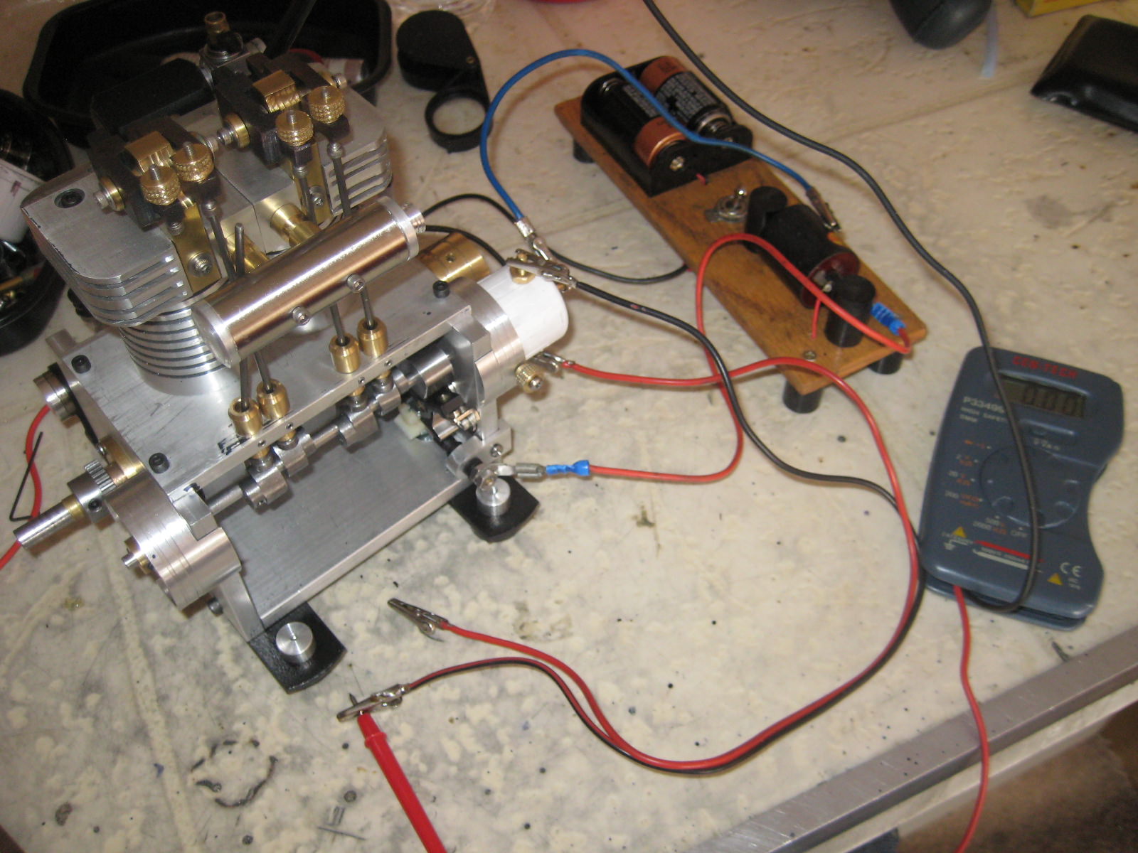
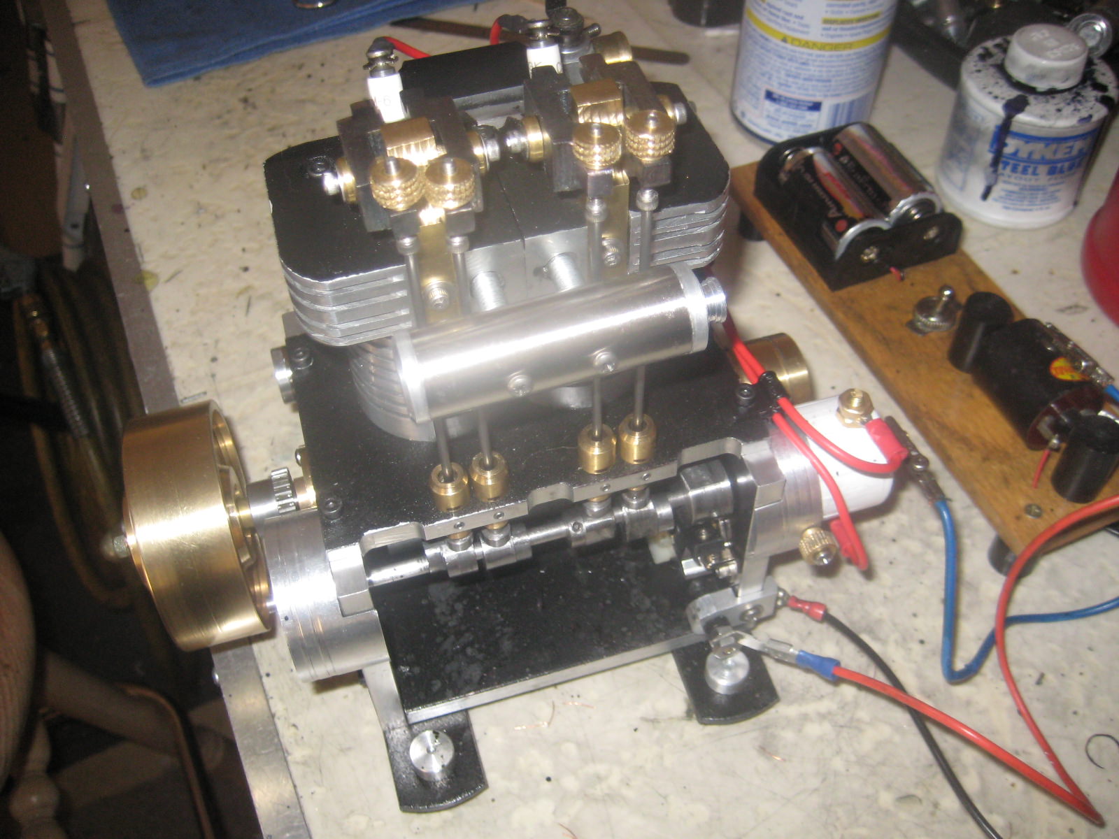
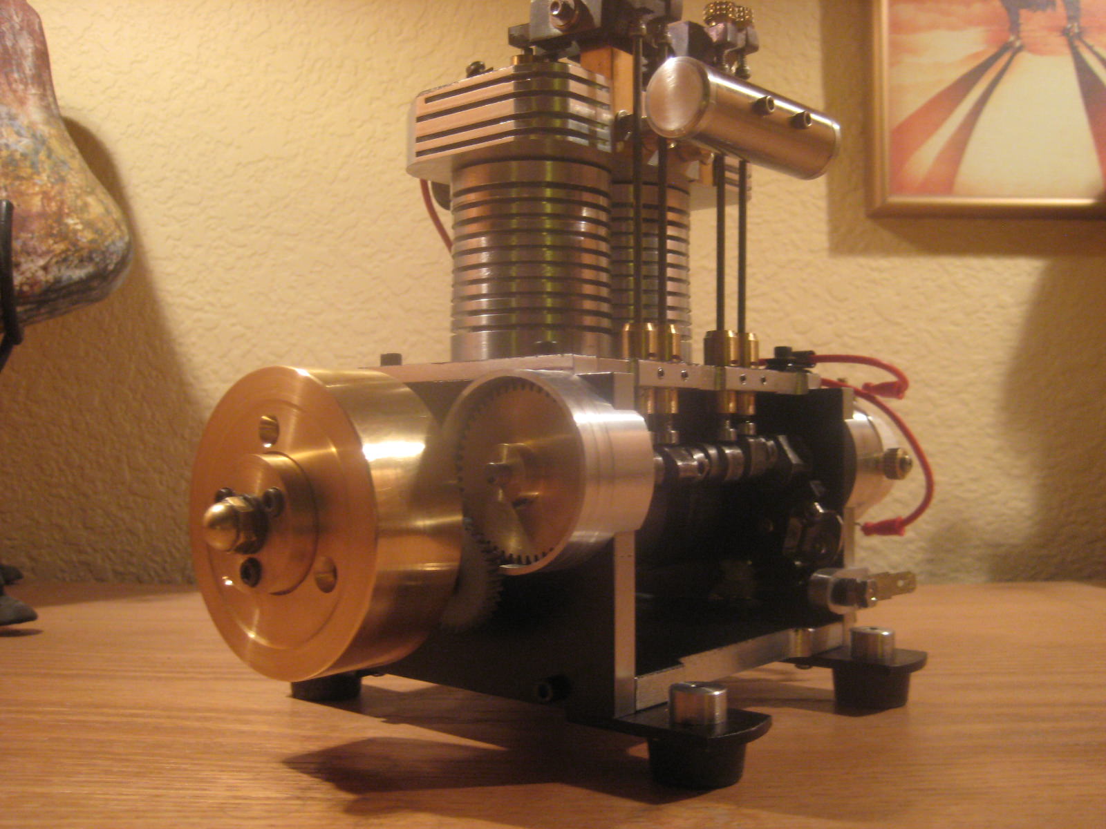
On my "Gemini" twin, I have a dedicated dual fire coil and 6 volt battery ignition mounted with the engine on a oak board. For "Overtime", I wanted a free standing engine and be able to use my traveling 3 volt battery pack & coil. To do so requires a distributor.

dTiF3VX.jpg


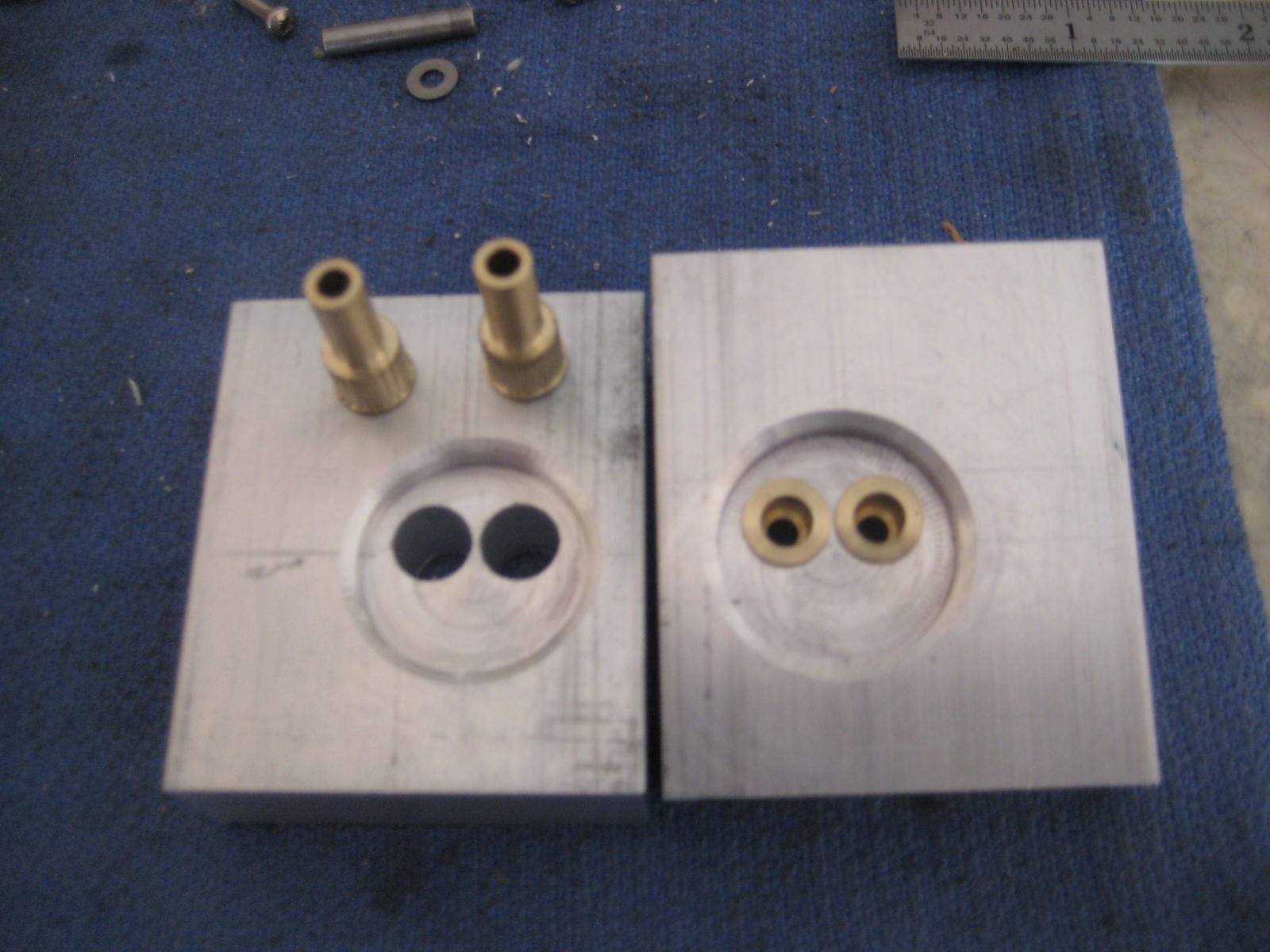
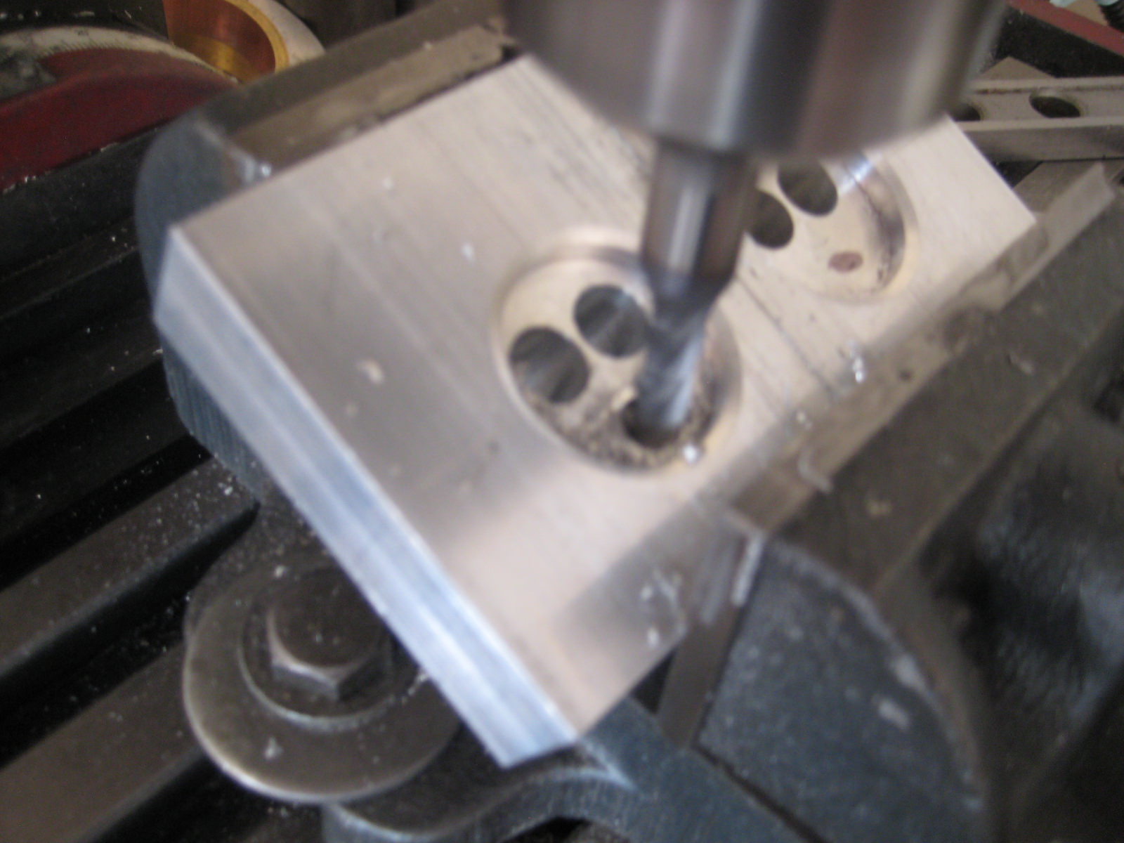
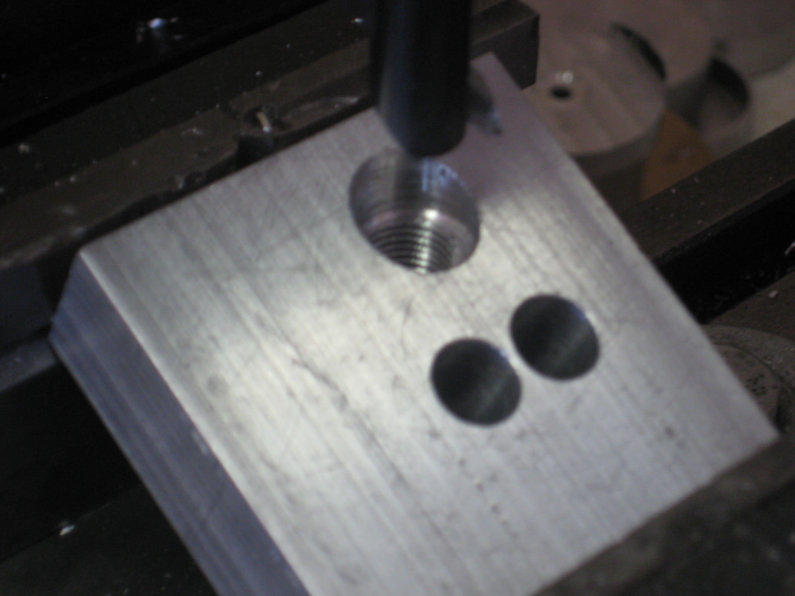
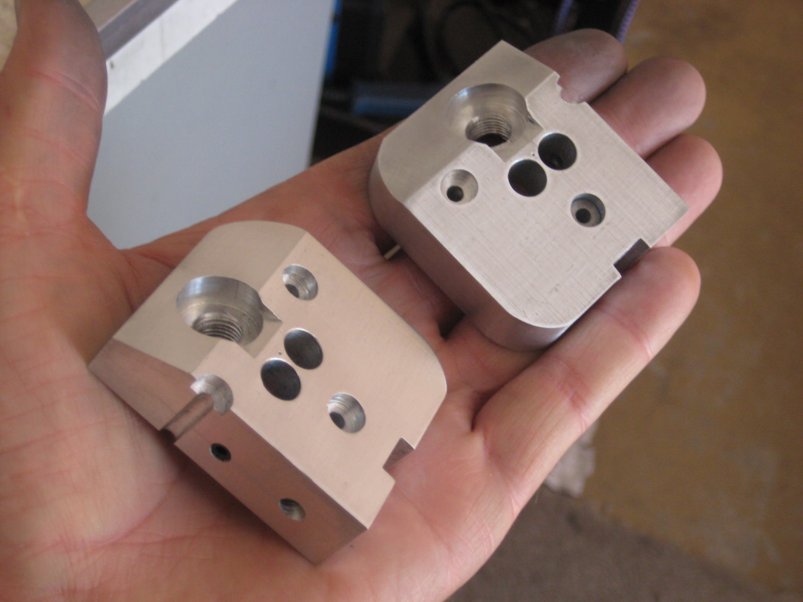
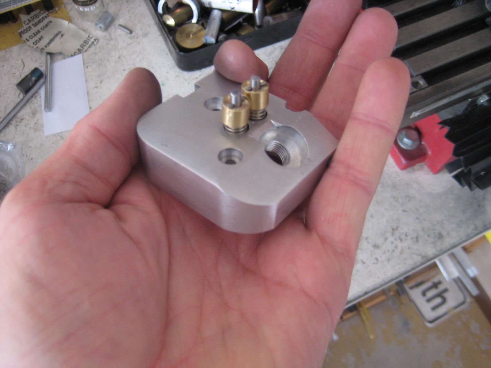
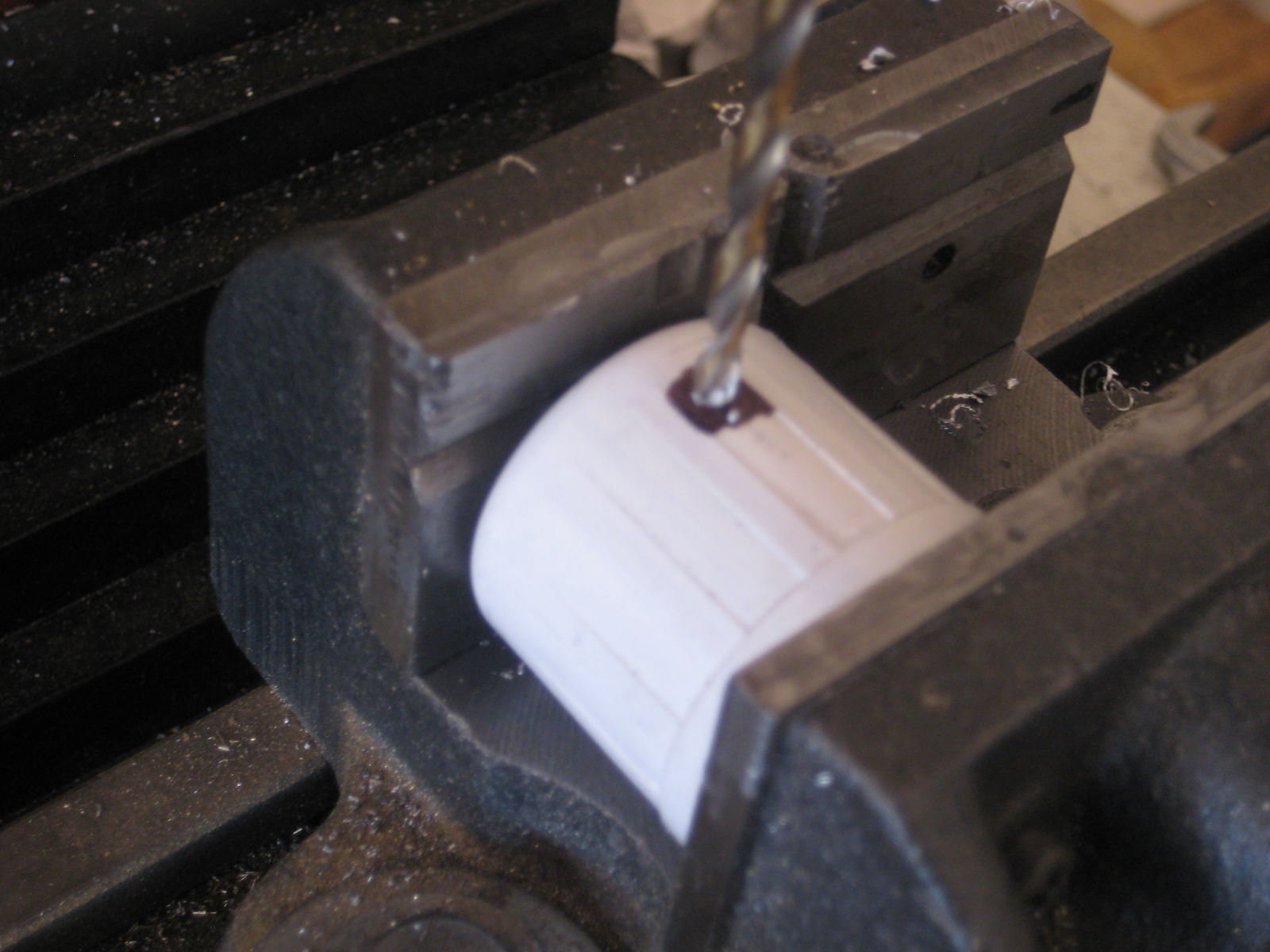
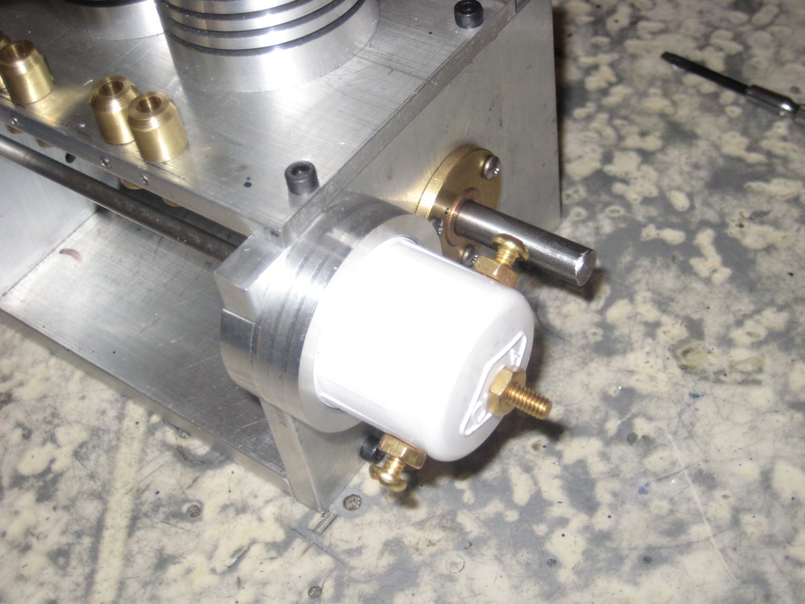
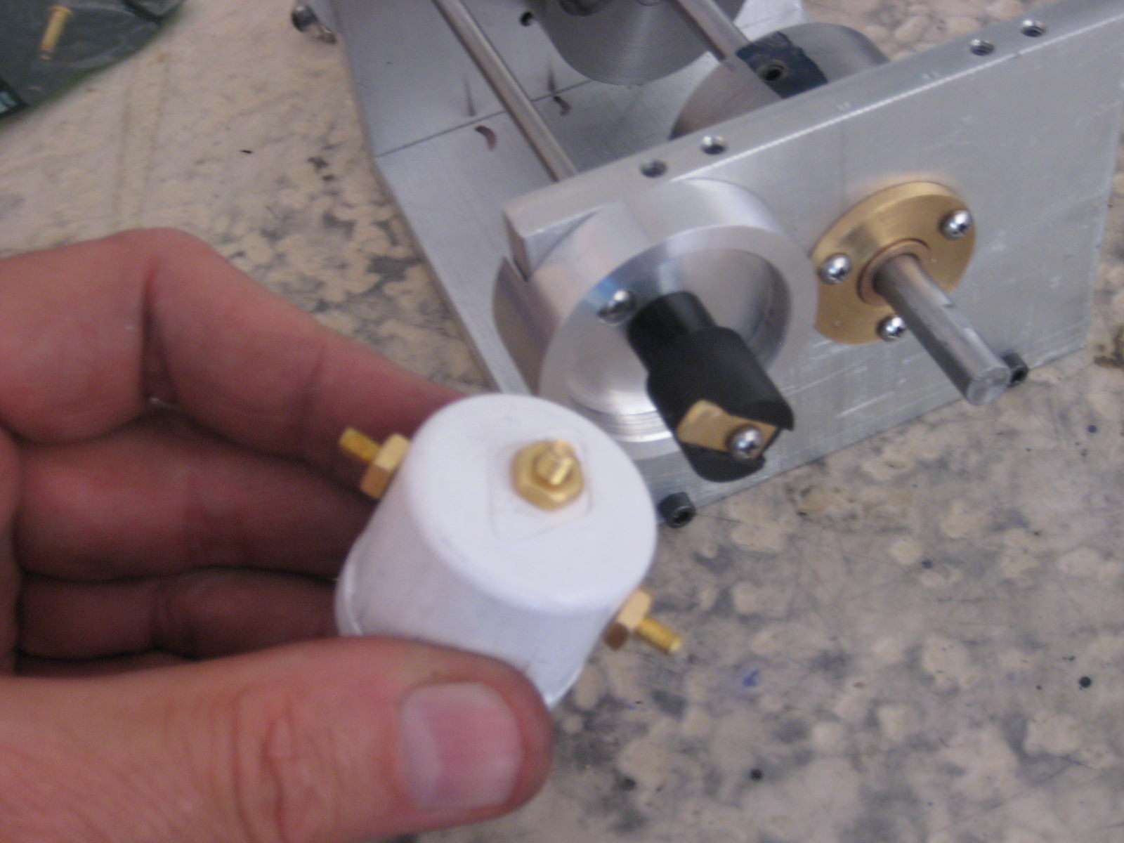
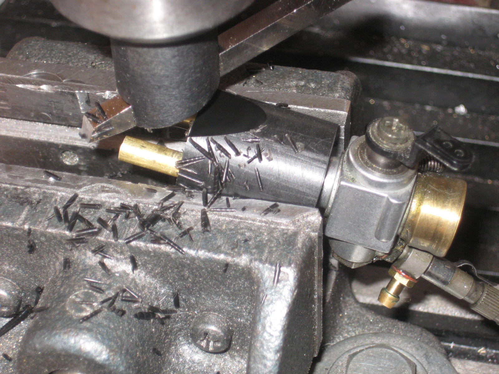
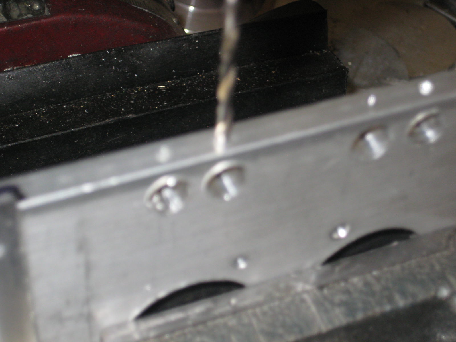
From Home Depot, I picked up both a 1-3/8in and 1 inch PVC end cap and bag of #8 brass machine screws & nuts. Used the 1 inch cap on the engine. Three drilled and taped holes located for coil and plug leads.

Fsw4D1Z.jpg


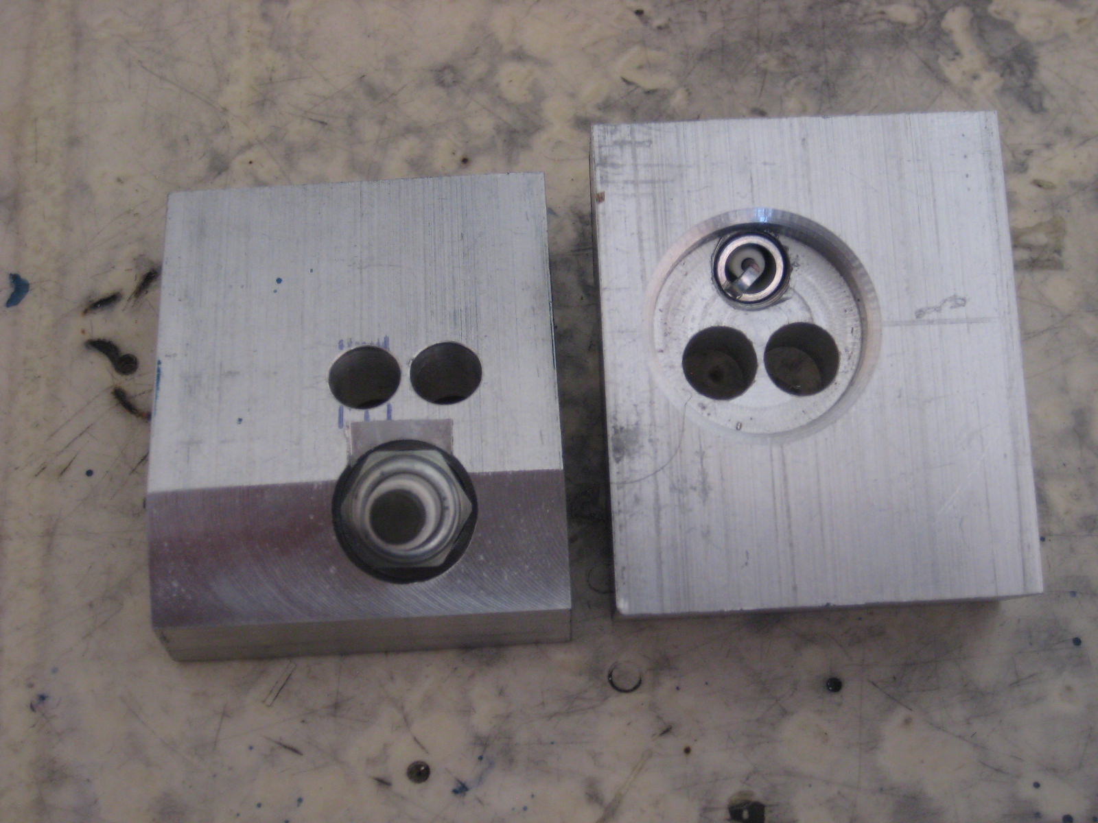
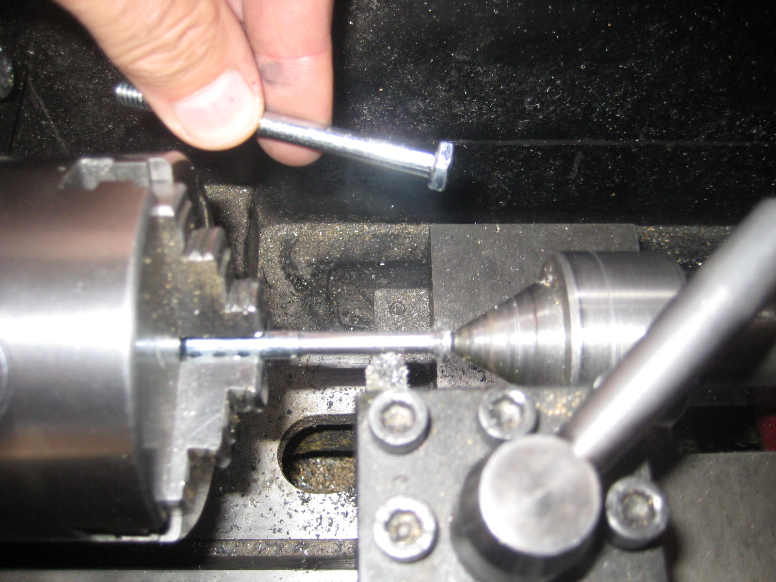
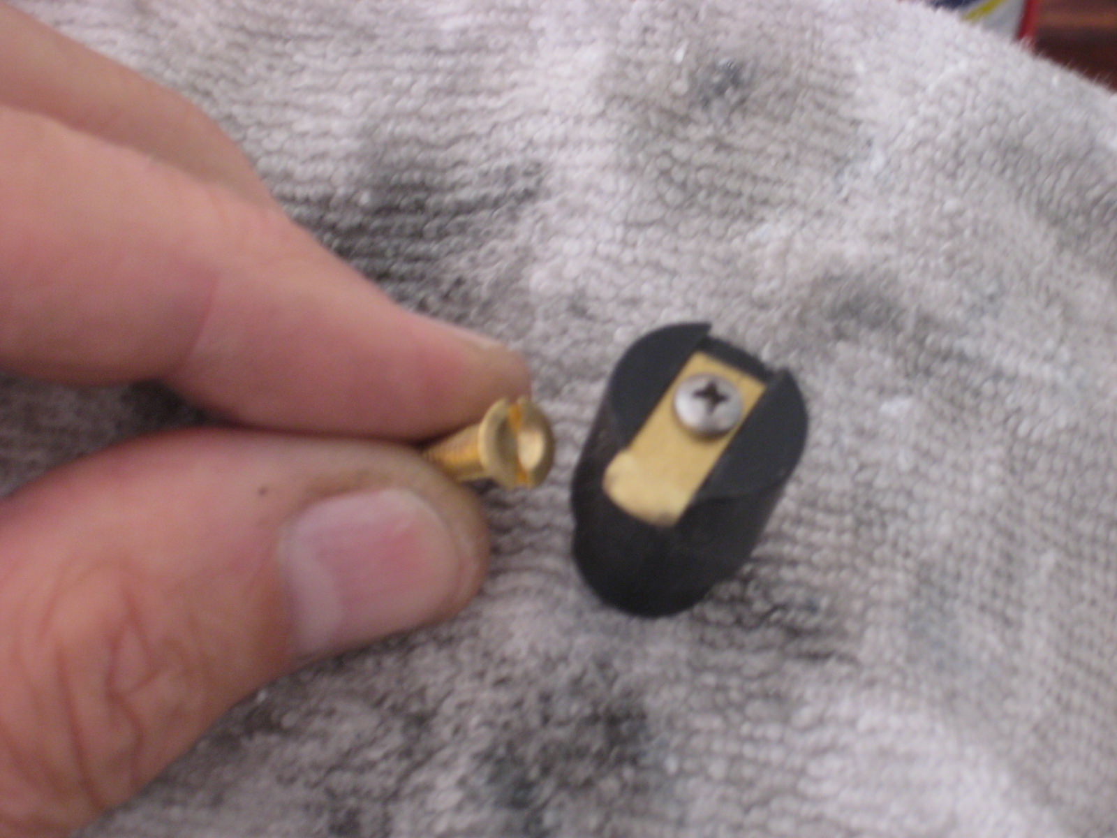
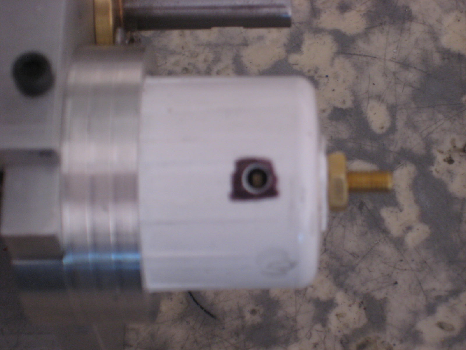
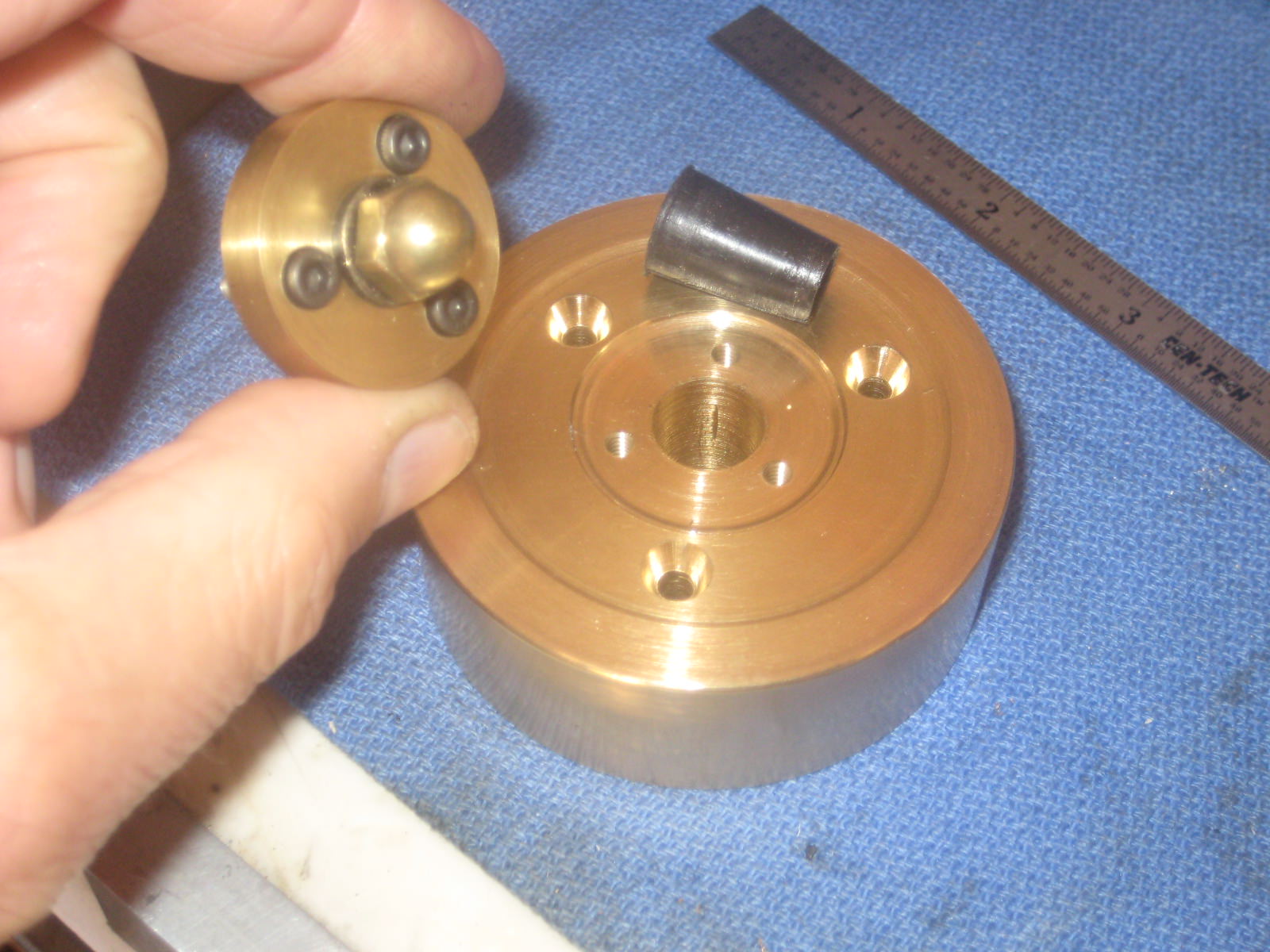
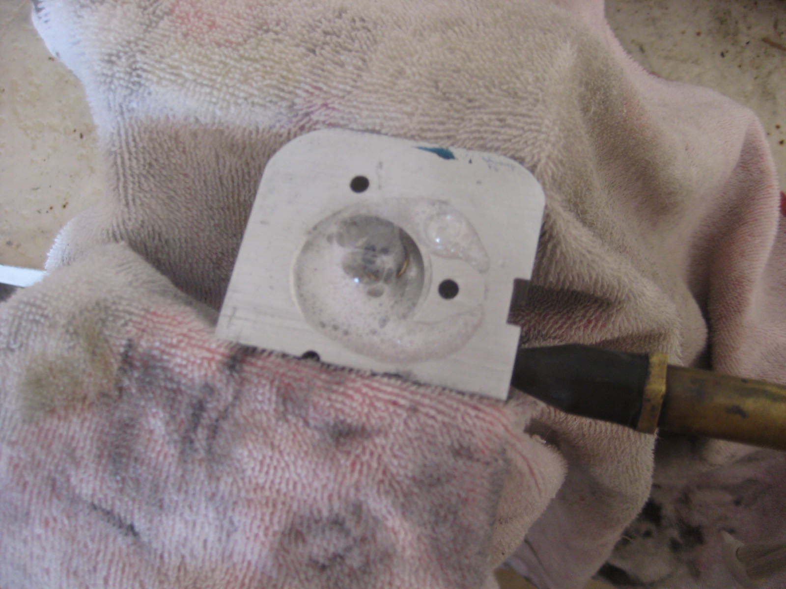
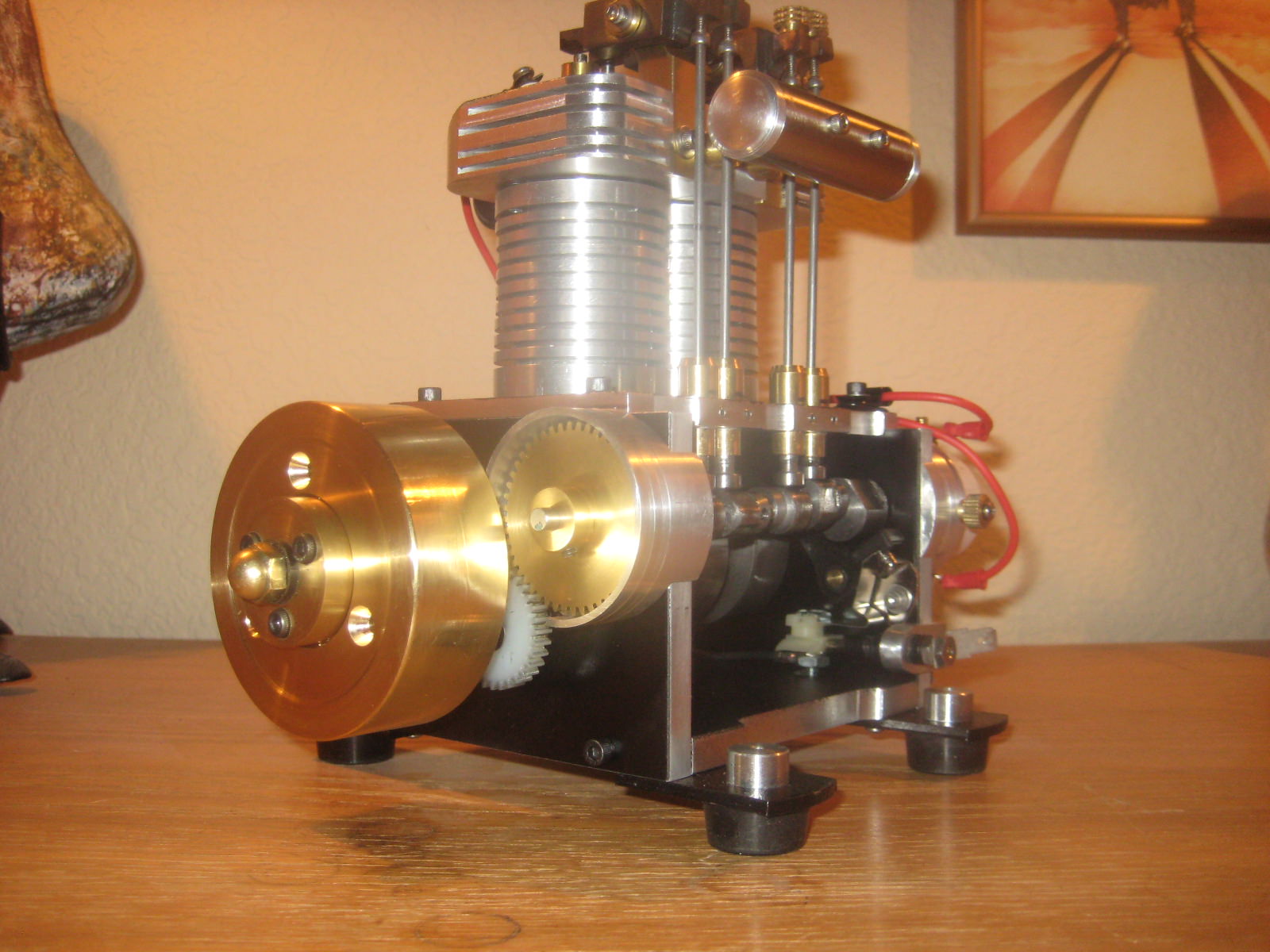
The rotor is Delrin with brass strap, stainless #4 screw. The coil screw is dished out to a ball & socket mate with the rotor screw head with a round nose tool bit on lathe. Threaded into cap from the inside, when placed over the distributor base it is threaded down till contact with the rotor screw and locked nutted in place.

D60yEYL.jpg


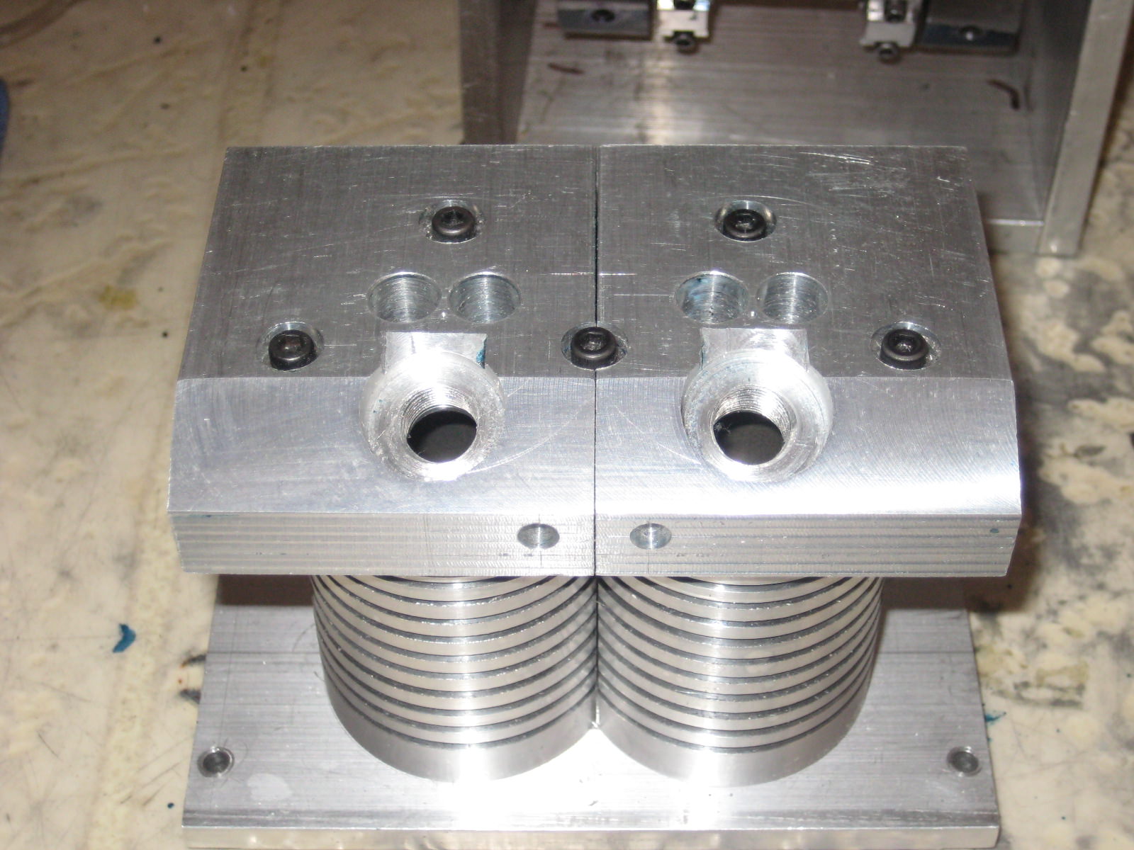
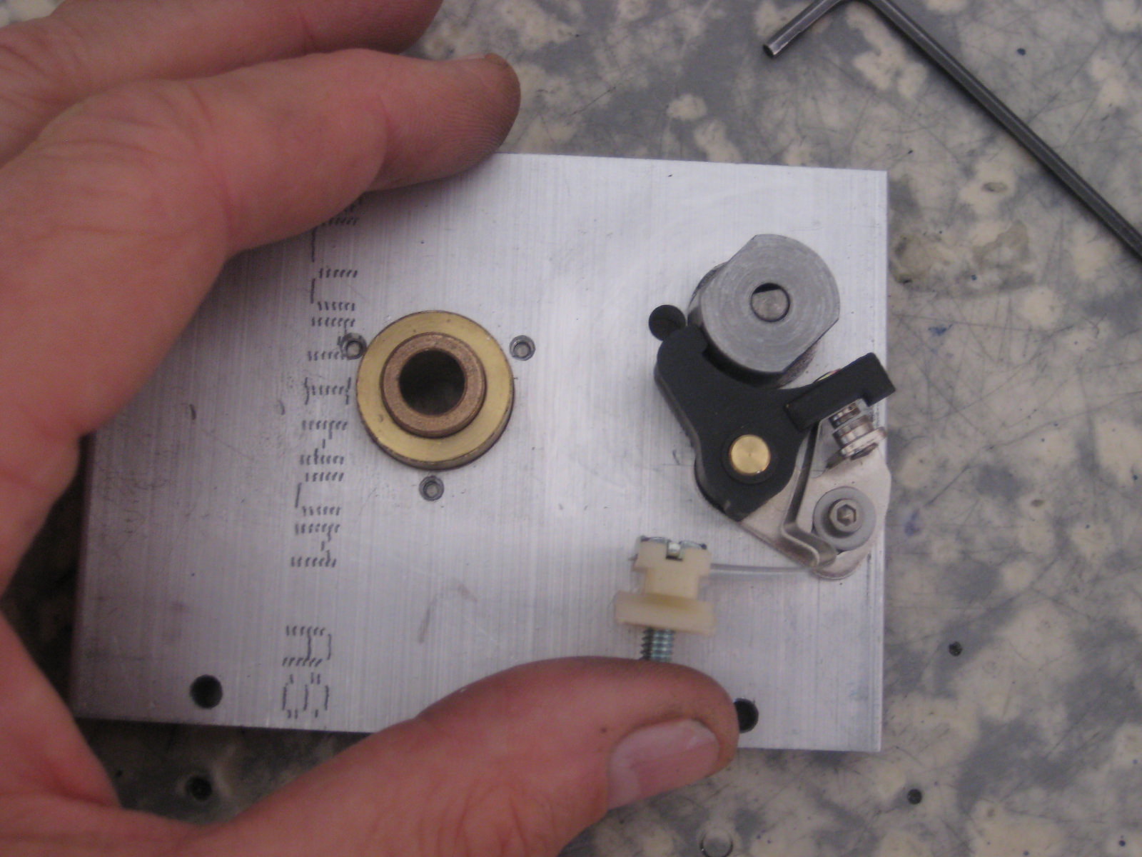
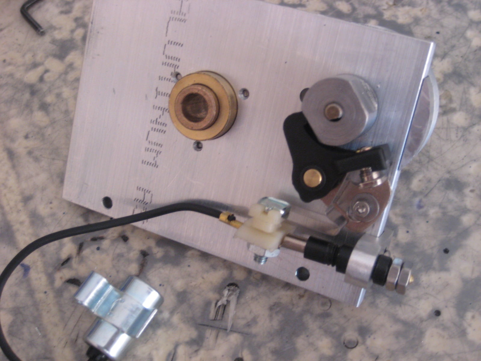
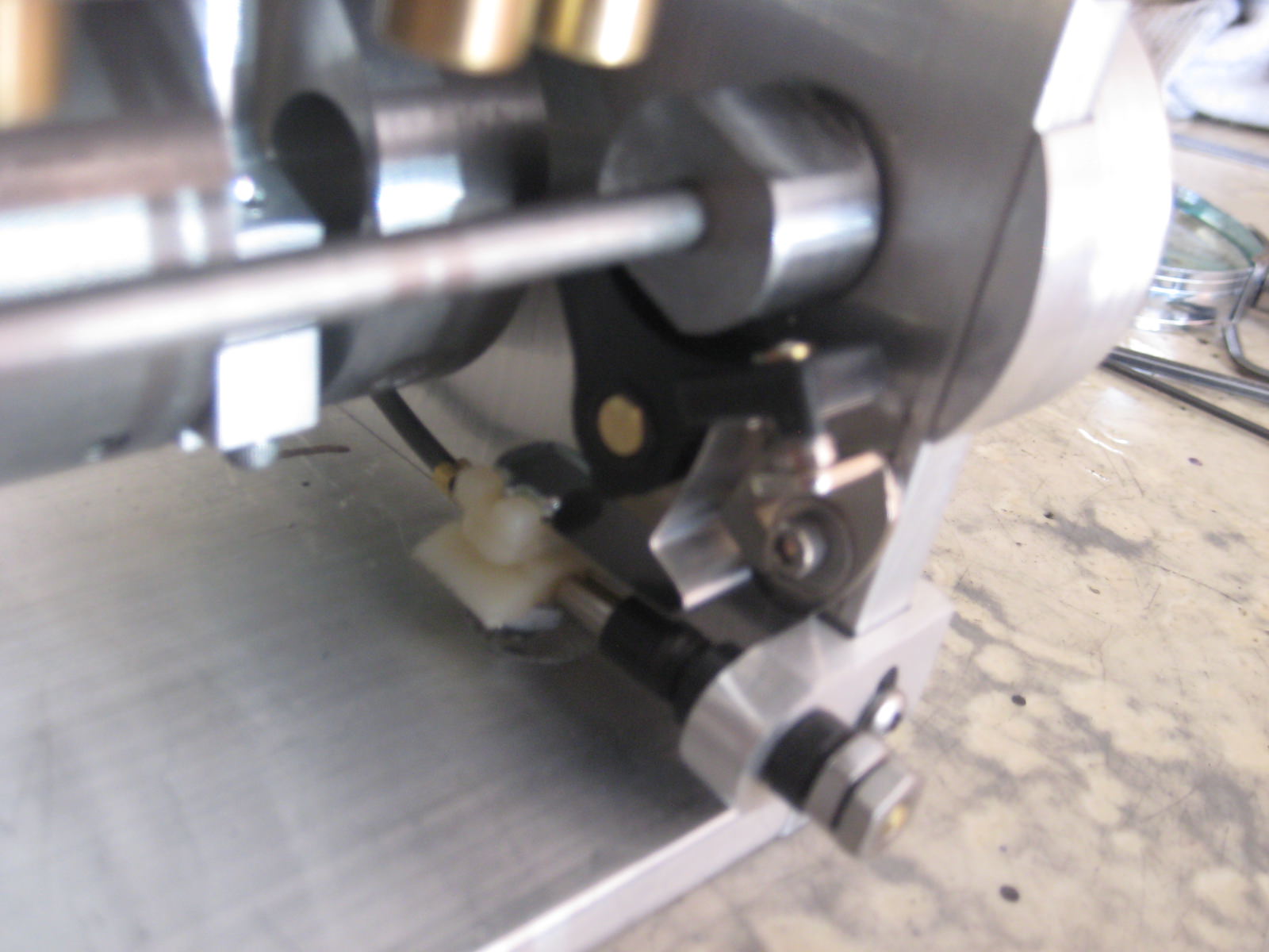
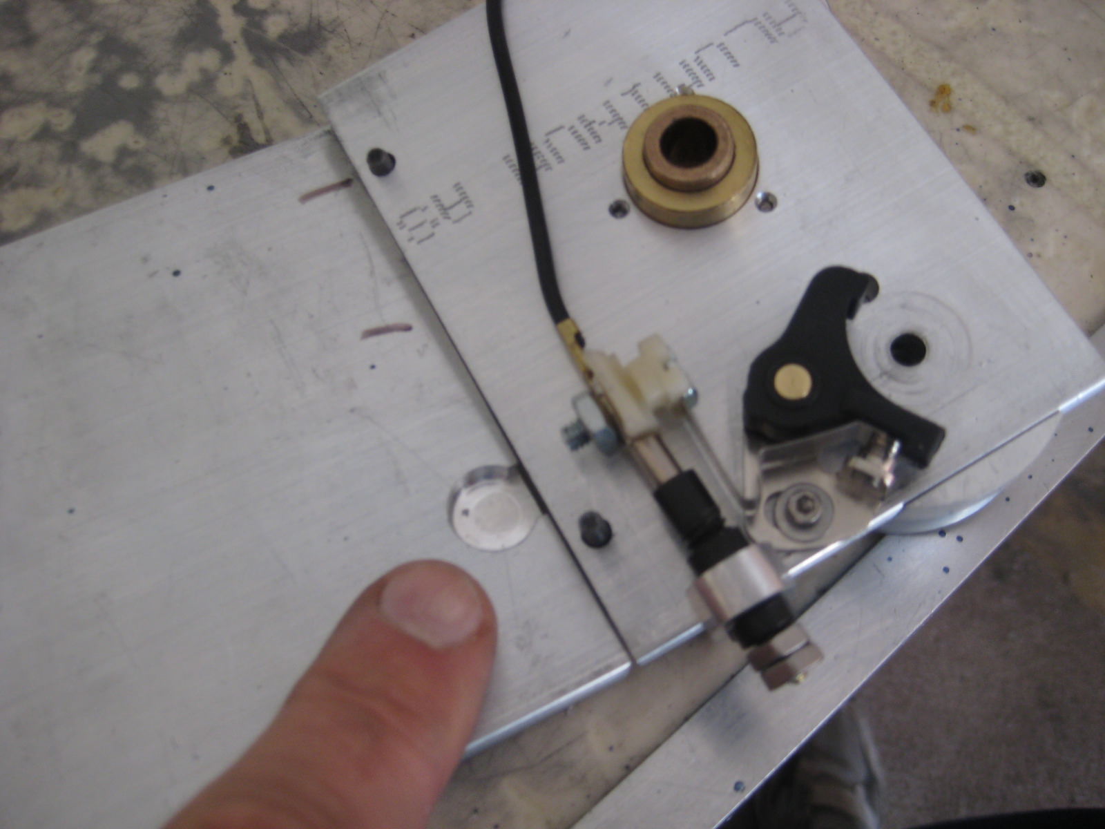
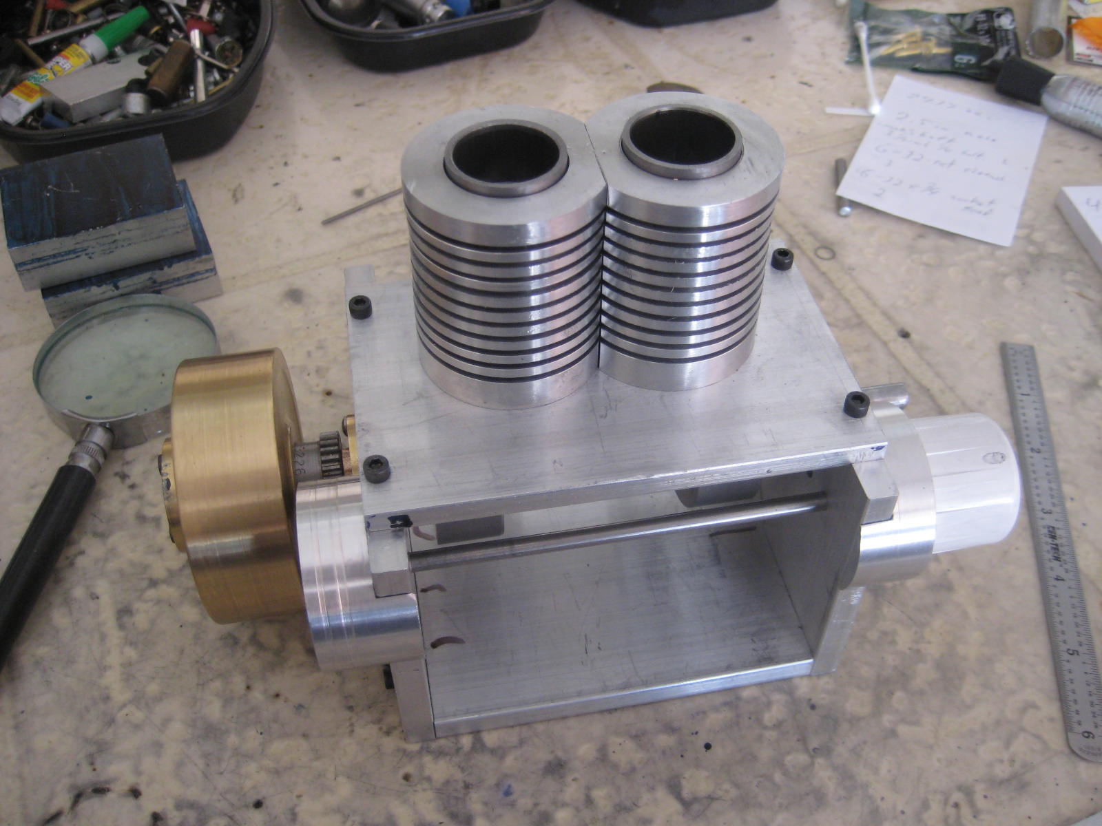
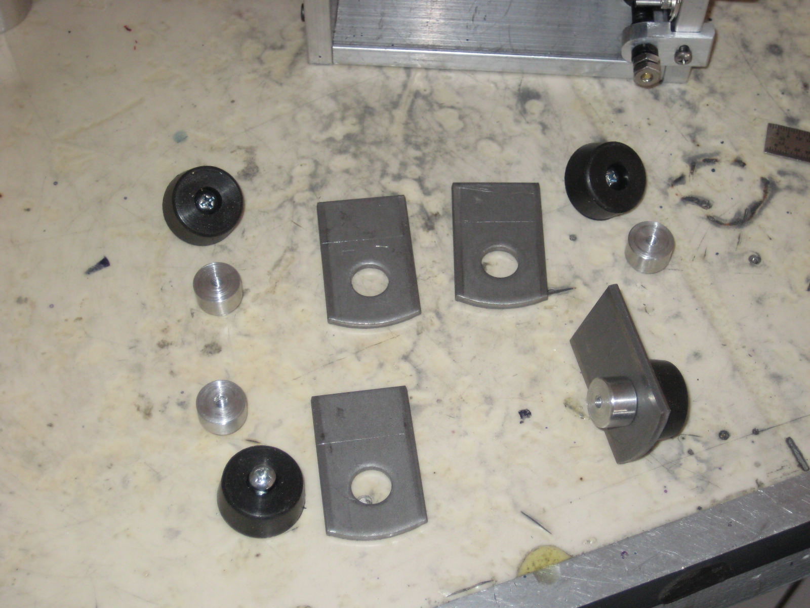
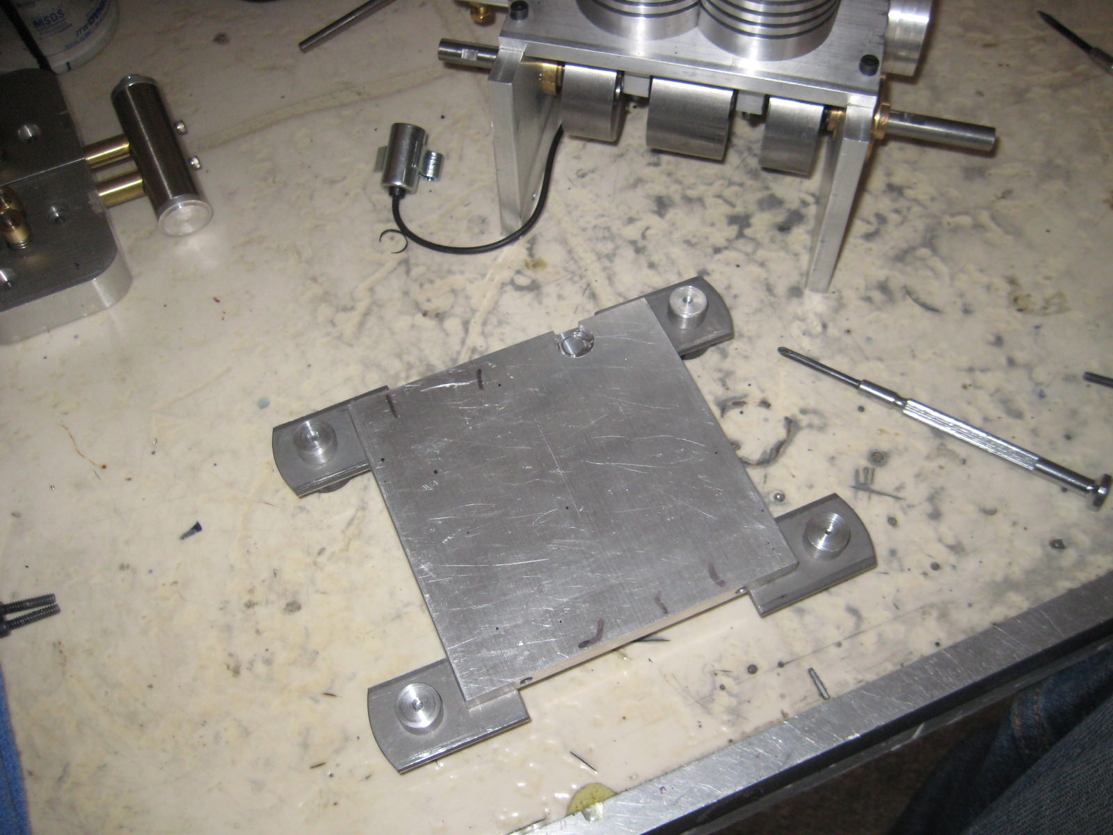
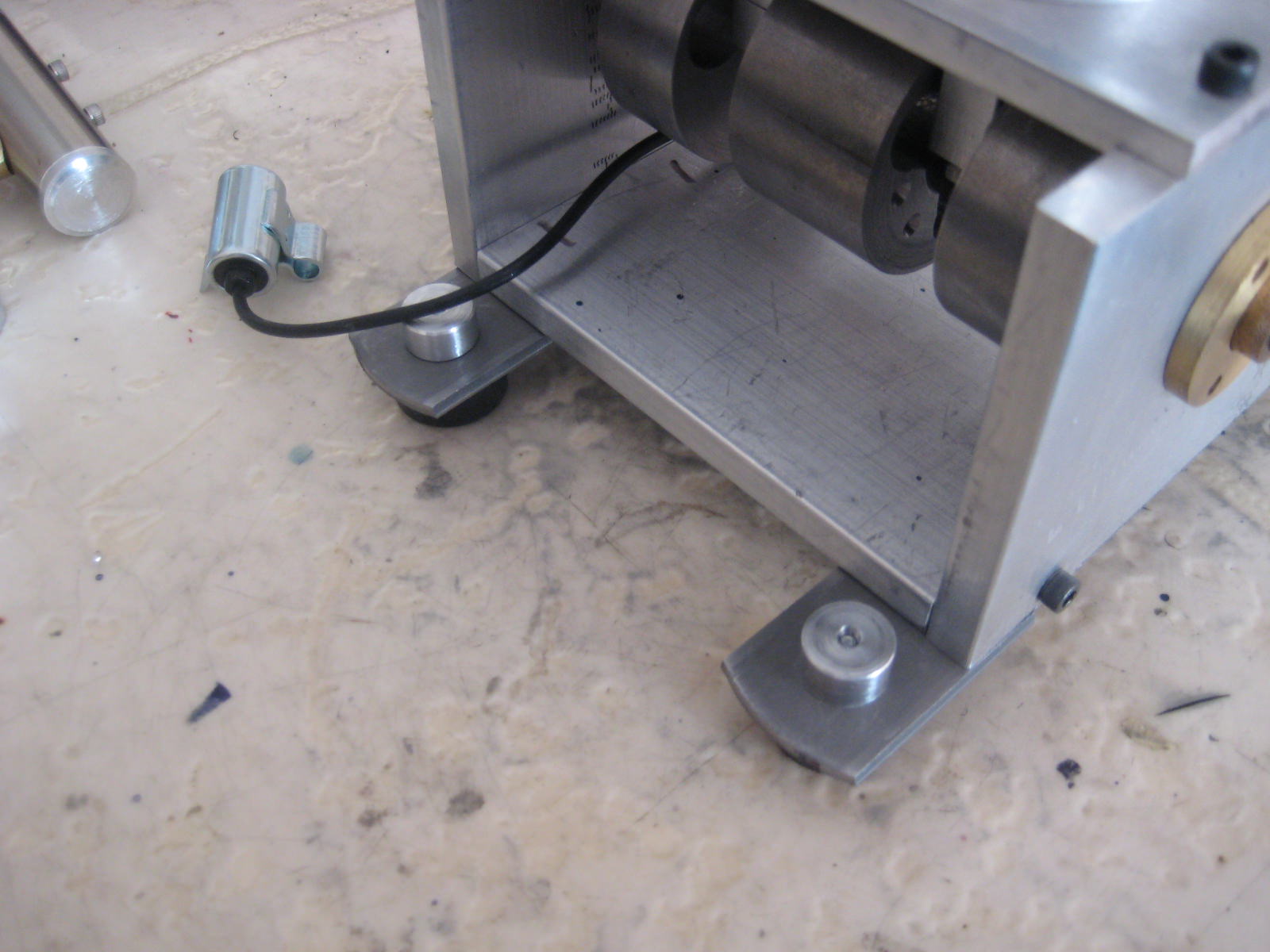
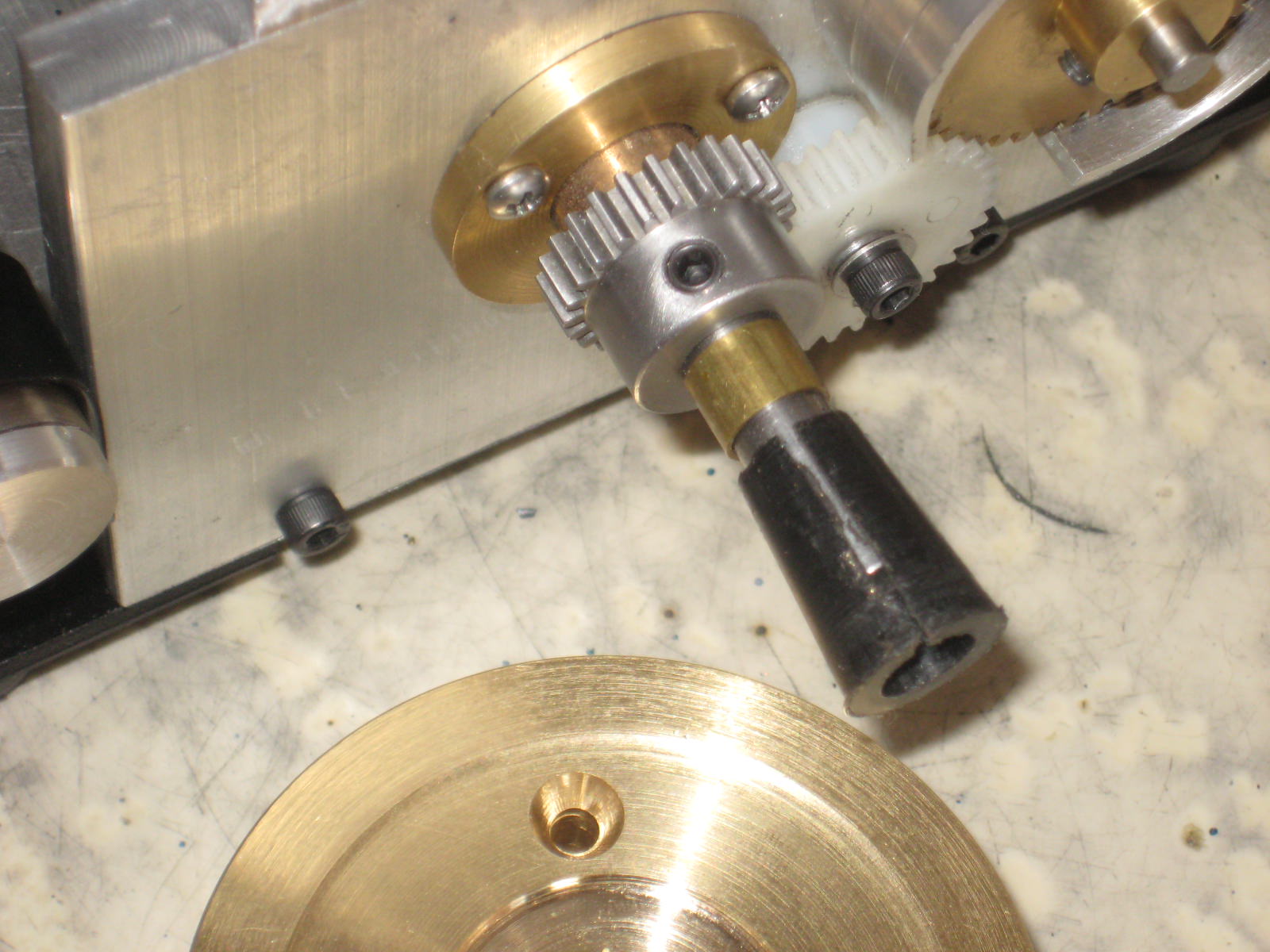
Rotor brass is located on the camshaft for line up with the plug leads. Distributor base is machined with a wrap around to the side of frame end plate and a matching piece serves as a timing gear guard at other end.

And32lQ.jpg


JtJVZYw.jpg


gCh2qT7.jpg


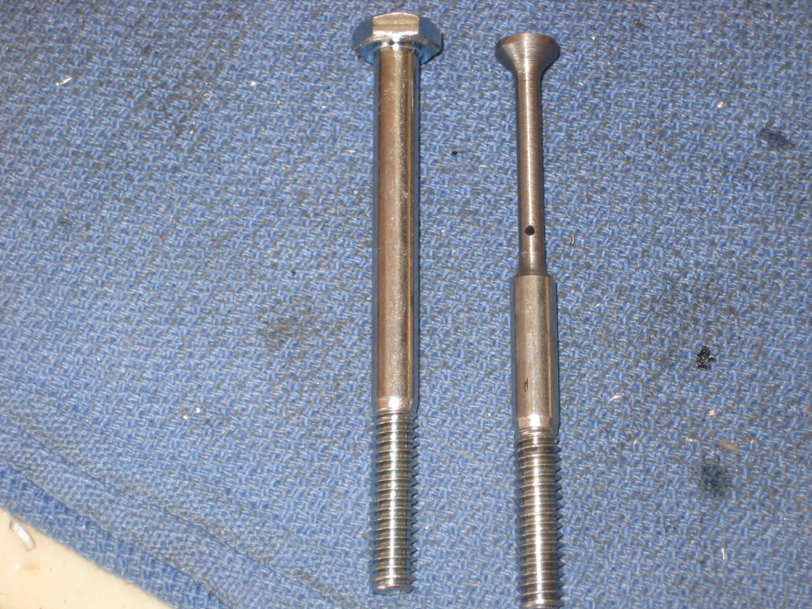
Plug lead screws are threaded in till contact and locked. Being a sweep contact, fine tune by finger rotating camshaft and feeling for it then. The screws were replaced with longer studs to fasten the wiring. Though a press fit to the base, a finger screw was added later to hold cap in its base.......cuzz I like doo dadz on the engine!:D
 
Last edited:
  • Like
Reactions: gus
T7XIzM8.jpg


Delrin intake is used with .10 to.15 size carburetor. Press fit brass tubes join intake to engine........I didn't like the looks with the carb jutting out from the engine too far and a duplicate was made at a right angle shown on engine here.

uMnCYjJ.jpg


A gathering of parts for the fuel tank. I used the decorative steel tube with a nickel finish for both the tank & muffler.

QKWQnVD.jpg


Cutting off the neck of mini liquor or energy drink bottles.... makes great fuel filler necks for fuel tanks.:eek:

mD9AENb.jpg


7ndhJMW.jpg


The exhaust port is threaded for a stud that is thru drilled and tapped for socket heads ( fillister heads cut off) to secure muffler. Stud is cross drilled to exit into muffler after spacing out with brass collars.


.wEc1.....Hey come back this weekend to the conclusion to Overtime's build with some tips, troubleshooting, the beauty shots and maybe a video!wEc1
 
hxOeENb.jpg


Instead of a press fit for the lifter guides, set screws are used to secure them to the deck. The lifter heads are small enough to pass thru removing them with the guides otherwise, depending on how long the lifter stems are, you may have to pull the cam to drop them out the bottom.

StKsdpH.jpg


The brass collar in front of the timing gear is the collet knockout. Pushing and twisting the flywheel, as it will ride over this collar pops the collet for removal then.

0tNAnqh.jpg


Flywheel retainer is drilled & tapped for a stud and brass acorn nut. Socket on the cordless drill for a starter drive!

09EIOzm.jpg


One of Overtimes cylinders had no compression. To reveal the leak, some dish soap suds over combustion chamber, a blow off nozzle from your compressor set to 10PSI into port shows where. In this case some epoxy dried on the valve guide seat preventing the seal.
 
g4EETh5.jpg


With the valve train set up now, I see that my lift and duration on the lobes is too great. The valve keeper bottoms on valve guide stem. Re-profiled the lobes and cut lobe lift back by .035 and I have a nice idle cam profile.

VG5R8ng.jpg


Checking the spark here. The distributor cap rocked some as the rotor made contact. Some filing of the rotor tip and a spin of the camshaft with electric drill for wear in left some brass dust under cap and proper clearances.

Whuyu1T.jpg


Some paint work in black and polishing the bright work...... and it looks like I'm ready to go!Thm:
 
wEc1..... to the reveal of my new engine!:) Work on "OVERTIME" started on Sept. 25th and first signs of life happened Dec. 15th.


W9cK7RW.jpg


I meet my goals & benefits of a distributor ignition, stronger crankshaft and boxed open frame.

Cw47RDE.jpg


Pleasant solitude hours in the garage, trips to metal supply and hardware store.

cl4E91S.jpg


And then its time!Thm:

qQd6K45.jpg


lAjWSDb.jpg


VbaqXvm.jpg


....Well that about does it for Overtime........(not so fast LONGBOY.... :mad:.....WHERE'S THE VIDEO?) ...Geez you guys are a tough crowd! :D

[ame]https://www.youtube.com/watch?v=qh09Fsku3ZU&list=UUSN_jfvtt4ISxTJ-9cKND8w[/ame]

Hey thanks for following along on OVERTIMES story.:) See my other model engine projects on YouTube, Longboy4. Thm:Dave
 
Hi LongBoy,

Great Engine. Your Prefabbed/bolt on crankcase proven and stood up very well. Will find time to build a single cylinder engine.
Meanwhile spending ample time read and comprehend Howell V-2 Prints before jumping into the cold water.Material coming in midweek. Weather warming up there??
 
Am following your build with open mouth!!! fantastic!!!!!
missing the pictures of the distributor build (and a lot others too)
 
All the photos are JPG files Peter. They show up for me on this forum. Maybe try one of my other logs for distibutor views. .... Dave
Well, totay they are here - yesterday just x-ed icons for over 15 pics - the mysteries of the internet...
Thanks nevertheless
P
 
Back
Top